

Page 1
Instruction Book Snow Thrower Model 6100
Read and keep this book for future reference. This book contains important information on
SAFETY, ASSEMBLY
OPERA
TION, AND MAINTENANCE.
,
OM-6100
Page 2

NO TE : This unit is equipped with an interna l combustion engine
and mus t not be us ed on or nea r any unimproved
fores t-covered, brus h-covered or grass-covered land unles s
the engine’s exhaust sys tem is equipped with a spark arrester
meeting applicable local or state laws (if any). If a s park a rrester
is us ed, it mus t be maintained in effective working order by the
operator.
In the S tate of C alifornia, the above is required by law (S ection
4442 of the C alifornia P ublic R esources Code). O ther states
may ha ve s imilar laws. F ederal laws apply on federal lands. S ee
an Authorized S ervice C enter for a spark a rrester for the
muffler.
Engine Exhaust, some of its constituents,
and certain vehicle components contain
or emit chemicals known to the State
of California to cause cancer and birth
defects or other reproductive
harm.Battery
posts, terminals and related accessories
contain lead and lead compounds, chemi-
cals known to the State of California to
cause cancer and birth defects or other
reproductive harm.
WASH HANDS AFTER HANDLING.
OM6100
2
Page 3
1
2
3
5
4
6
OM6100
3
Page 4
7
8
9
1
1
4
3
1/8” (3mm)
3
2
7
2
5
11
10
12
OM6100
2
3
1
4
4
4
5
6
Page 5
4
2
1
5
3
13
14
3
4
2
5
3
6
4
15
1
5
16
OM6100
1
5
Page 6

C ONTE NT S
P R ODUC T INFOR MA
OWNE R ’ S INF OR MA
INTE R NAT ION A L P IC TOR IAL S 7
AS S EMB LY 9
OPE R ATIO N 10
MA INT ENA NC E 12
MA INT ENA NC E C HA R T 12
TR OUB LE S HOOT ING C HAR T 14
TWO Y E A R L IMITE D WAR R R A NTY
Ardis am
that this unit s hall be free from defects in
materia l and workmanship under norma l us e
and service for a period of Two (2)
the da te of purcha se; howeve r, this warra nty
does not cover engines, acces sories (such as
electric starters) and Normal Wear P arts (except
as noted below) .
s ee the wa rranties covering thes e particular
pa rts. If you a re uncertain whether your unit
contains or is equipped with one or more of
thes e parts, cons ult your dealer prior to
, Inc. warrants to the original purc haser
F or a dditional information,
TIO N
TIO N
Yea rs
from
purchase. S ubject to the terms a nd conditions
noted in this Limited Wa rranty, we shall, a t our
option, re pair or replace a t no cos t to the original
6
purchaser any part covered by this L imited
6
Wa rranty during the a pplicable wa rranty period.
Norma l We ar P arts a re defined as drive belts,
auge rs, s hear pins, tires a nd hea dlights. T hese
parts a re warranted to be free from defects in
materia l and workmanship as delivered with the
product. Any claim for re pair or replacement of
Norma l We ar P arts mus t be made within thirty
(30) days of the date of purchase. N o claims
involving da mage ca used from materia l us e,
abus e or mis use will be honore d.
This Ardisam
Wa rranty is your exclus ive remedy; however,
this warra nty is void or does not a pply to any
unit that has been tampere d with, altered,
misused, abused or use d for rental or other
commercial a nd/or profes siona l
(non-homeowner) uses . Your warranty does not
cove r minor mechanical adjustments which a re
not due to any defect in ma terial or
workmanship. For a ss istance in ma king such
adjus tments, cons ult your Instruction B ook.
To ma ke a claim under this Ardisam
Year L imited
authorized in advance), the defective part along
with your proof of purchase to an Authorized
S ervice Center near you. To locate the nea rest
, Inc.
Warra nty
Two (2)
Yea r L imited
, return the unit (or if
,Inc.
Two(2)
Authorized S ervice C enter,
service at 1800-345-6007. If you return the entire
unit, we will repair the unit. If we a uthorize the
re turn of the defective part only,
re place or repair the part.This Ardisa m,
Two (2) Y
specific legal rights, a nd you may also ha ve other
rights which va ry from state to state.
Warra nty is given in lieu o f all other
ex pres sed and implie d warran ties includ ing
the implied wa rra nty of merc han tability and
warr anty of fitnes s for a particular pu rpos e.
If you need additional information on this written
warra nty or assistance in obtaining s ervice,
write:
info@ ardisam. com
Ardis am ,lnc
1690 Elm S treet
P .O. Box 666
C umberland,wi 54829
P ho ne
715-822-2415
Fax:715-822-2223
1-800-345-6007
www.ardisa m.com
ea r L imited W
call Ardisam customer
we will either
Inc.
gives you ,
ar ranty
This Limited
P R ODUC T INF OR MATIO N
The owner must be certain that all the product
information is included with the unit. This
information includes the INS T RUC TIO N
BOOK S , the R E PLAC E ME NT PAR TS L IS T and
the
WAR R ANTIE S . This information must be
included to make s ure s tate laws and other laws
are followed.
OWNE R 'S INFOR MA
This ins truction book is written for a person with
some mechanical ability. L ike most service
books , not all the s teps a re described. S teps on
how to loos en or tighten fa steners are steps
anyone ca n follow with some mechanical ability.
R ead and follow these instructions before you
use the unit.
K now you r produc t:
and how the unit operates , you will get the best
performance. As you read this manual, compare
the illus trations to the unit. Learn the location
and the function of the controls. To help prevent
an accident, follow the operating instructions
TION
If you understand the unit
and the safety rules. K eep this ma nual for future
reference.
IMP OR TANT: Many units are not ass embled
and are sold in ca rtons. It is the res ponsibility of
the owner to make sure the a ss embly ins tructions in this manual are exactly followed. O ther
units are purchased in a n as sembled condition.
On assembled units , it is the res ponsibility of the
owner to make sure the unit is correctly a ssembled. The owner must carefully check the
unit ac cording to the instructions in this manual
before it is first used.
WA RNING : L ook for this s ymbol to indic ate
important s afety pre cautions . T his s ymbol
indic ates : “ Atte ntion! Bec ome Alert! Your
S afe ty Is A t R isk.”
R es pons ibility O f T he Owner
The res pons ibility of the owner is to
follow the ins tructio ns below.
1. C arefully rea d and follow the rules for s afe
opera tion.
2. Follow a ll the as se mbly a nd preparation
instructions.
3. Ins pect the unit.
4. Make sure that the operator of the unit
knows how to correc tly us e a ll s tanda rd
and acces sory equipment.
5. Operate the unit only with gua rds, s hields,
and other safety items in place and working
correctly.
6. C orrectly adjus t the unit.
7. S ervice the unit only with authorized or approved replacement parts.
8. C omplete all maintena nce on the unit.
E nvironmental Awarenes s
Do not fill the engine’s fuel tank completely
full.
Dra in fuel for off-season s torage.
Us e only unleade d ga soline.
S ervice the air clea ner regularly.
Tune -up the engine regula rly.
Keep equipment in efficient operating
condition.
Dis pose of used engine oil properly.
OM6100
6
Page 7
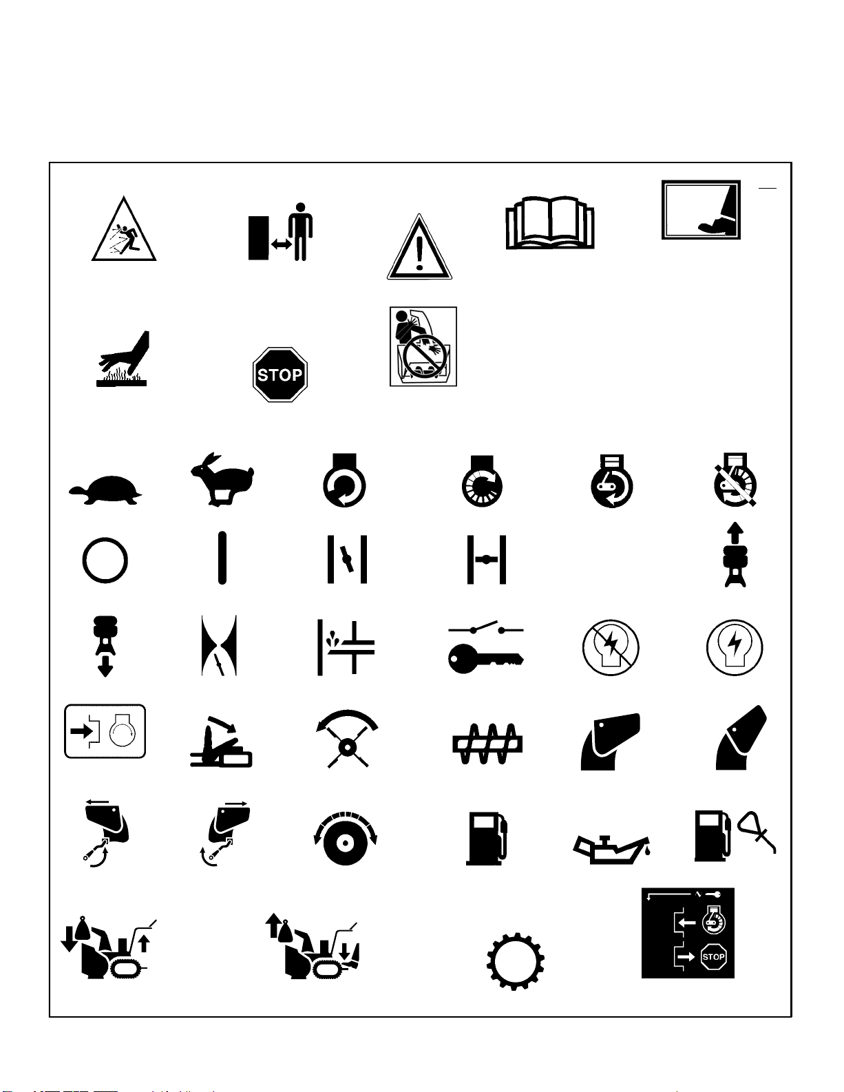
INT E R NATIONAL P IC TOR IA LS
IMP OR TANT: The follo wing pictoria ls ma y be
located o n yo ur u nit or o n lite rature s upplied
with the product. B efore you oper ate th e
unit, learn an d unders tand th e purpos e for
ea ch pic torial.
Safety Warning Symbols
DA NG ER
Thrown O bjects .
K eep B ys tanders Away .
WA RNING
Ho t Surface
DA NG ER
Thrown O bjects .
K eep B ys tanders Away .
S TO P
WA RNING
DA NG ER
S top The E ngine B efore
Un clo ggin g Dis charge
C hute!
IMP OR TANT
R ead O wner's Manual
B efore Opera ting
This Mac hine.
Control And Operating Symbols
S low Fas t E lec tric S tart E ngine S tart E ngine R un
DA NG ER
Av oid Injur y F rom
R otating A uger. K eep
Ha nds , F eet And
C lothing Away.
E ngine Off
18
E ngine S top On C hok e Off C hoke O n
R evers e
P us h To E ngage
E lec tric S tarter
Dis char ge L E FT Dis charge R IG HT
KGS
Throttle P rimer B utton Ignitio n K ey Ignitio n Off Ignition On
E nga ge
Auger C lutc h Auger C ollec tor
Drive Clutch
KGS
Fuel Oil Fue l Oil Mixture
N
Neutr al
Dis charge DO WN Dis charge UP
For ward
We ight T rans fer
L ift Handle To E nga ge
OM6100
We ight Trans fer
Depres s Pedal To
Dis engag e
Tran smis s ion
Ins ert T o
Ignition Key
R un , P ull Ou t To S top
7
Page 8

S afe Operation Prac tices for S now T hrowers
As R ecommended B y: A merican National S tandards Ins titute.
IMP OR TANT: S afety s ta ndards re quire opera tor
pres ence controls to minimize the risk of injury.
Your snow thrower is equipped with s uch c ontrols. D o not attempt to defeat the function of the
opera tor presence control under a ny circumstances.
Training
1. R ead the operating a nd service ins truction
manua l ca refully. B e thoroughly familiar with
the controls a nd the proper use of the equipment. K now how to s top the unit and dis engage the c ontrols quickly.
2. Never a llow children to operate the equipment. Neve r allow adults to operate the
equipment without proper ins truction.
3. Keep the a rea of opera tion clear of all persons, particularly s mall children and pets.
4. E xerc ise caution to avoid s lipping or falling
es pecially when operating in revers e.
P repar ation
1. Thoroughly inspect the area where the equipment is to be us ed and remove all doorma ts,
sleds , boards , wires , a nd other foreign objects .
2. Dis engage all clutches before s tarting the engine (motor).
3. Do not operate the equipment without wearing a dequate winter outer ga rments. We ar
footwear that will improve footing on s lippery
surfac es.
4. Ha ndle fuel with ca re; it is highly flammable.
a. Us e an approved fuel c ontainer.
b. Never remove fuel tank cap or a dd fuel to
a running engine (motor) or hot engine
(motor).
c. F ill fuel tank outdoors with extreme care.
Never fill fuel tank indoors .
d. R e place fuel cap s ecurely and wipe up
spilled fuel.
e. N ever store fuel or snow thrower with fuel
in the tank inside of a building where
fumes may reach an open flame or s park.
f. C heck fuel supply before ea ch us e, allow-
ing space for expansion as the heat of the
engine (motor) a nd/or s un ca n ca use fuel
to expand.
5. For all units with electric starting motors use
electric starting extension cords certified
C SA/UL . Us e only with a receptacle that ha s
been ins talled in accordanc e with loc al inspection authorities.
6. Adjus t the snow thrower he ight to clear gravel
or crus hed rock surface.
7. Never attempt to ma ke any a djustments
while the engine (motor) is running (except
when specifically re commended by manufac turer).
8. Let engine (motor) and snow thrower adjust
to outdoor temperatures before starting to
clear s now.
9. Always wear sa fety glasses or eye shields
during operation or while performing a n adjustment or repair to protect eyes from foreign
objects that may be thrown from the snow
thrower.
Operatio n
1. Do not operate this machine if you are taking
drugs or other medication which can ca use
drowsines s or affect your a bility to operate
this machine.
2. Do not us e this ma chine if you a re me nta lly
or physica lly unable to operate this mac hine
safely.
3. Do not put hands or feet nea r or under rotating pa rts . Keep clear of the discharge opening a t all times .
4. E xerc ise extreme caution when opera ting on
or cros sing gravel drives , walks or roa ds.
S tay a lert for hidden haz ards or traffic.
5. After striking a foreign object, stop the e ngine
(motor), remove the wire from the spark plug,
thoroughly ins pect snow thrower for any
dama ge, and re pair the dama ge before restarting and operating the snow thrower.
6. If the unit s hould s ta rt to vibrate a bnormally,
stop the engine (motor) and check immediately for the cause. Vibration is generally a
warning of trouble.
7. S top the engine (motor) whenever you leave
the operating position, before unclogging the
auge r/impeller housing or dis charge chute
and when ma king any repairs, adjustments,
or inspections.
8. When cleaning, repairing, or inspecting, ma ke
certain the a uger/impeller a nd all moving
parts have stopped and a ll controls are disengaged. Dis connect the spark plug wire and
keep the wire a way from the s park plug to
preve nt accidental starting.
9. Take all pos sible precautions when leaving
the snow thrower unattended. Dis engage the
auge r/ impeller, stop engine (motor), a nd remove key.
10. Do not run the engine (motor) indoors, exce pt
when starting the engine (motor) and for
trans porting the snow thrower in or out of the
building. Open the outs ide doors ; e xhaus t
fumes are dangerous (containing C AR B ON
MONO XIDE , an ODOR LE S S and DE ADLY
G AS ).
11. Do not clear s now acros s the fac e of slopes .
E xercise extreme caution when cha nging
direction on slopes . D o not attempt to clea r
steep slopes .
12. Never opera te the snow thrower without
proper guards, plates or other safety protective devices in place.
13. Never opera te the s now thrower near enclos ures , automobiles , window wells , drop- offs,
and the like without proper adjustment of the
snow dis charge angle. K eep children and
pets a way.
14. Do not overload the mac hine capacity by attempting to clear s now at too fast a ra te .
15. N ever operate the mac hine at high transport
speeds on slippery s urface s. L ook behind
and use care when backing up.
16. Never direct discha rge a t bys tanders or a llow
anyone in front of the unit.
17. Disengage power to the collector/impeller
when snow thrower is trans ported or not in
us e.
18. U se only attachments and a ccess ories approved by the manufa cturer of the snow
thrower (s uch a s tire chains, electric start kits,
ect.).
19. Never opera te the s now thrower without good
visibility or light. Always be s ure of your footing a nd keep a firm hold on the handles.
Wa lk;neve r run.
20. Do not over- reac h. K eep proper footing and
balance at all times.
21. E xercise caution if operating on s teep s loping s urfaces.
22. T his s now thrower is for us e on s idewalks ,
driveways and other ground level surfaces .
23. Do not us e the snow thrower on surfac es
above ground level such as roofs of residences , ga rages , porches or other such
structures or buildings.
Maintenanc e A nd S torage
1. C heck s hear bolts a nd other bolts a t frequent
intervals for proper tightnes s to be s ure the
equipment is in safe working condition.
2. Never s tore the snow thrower with fuel in the
tank inside a building where ignition sources
are pres ent s uch a s hot water and space
hea te rs, c lothes dryers , and the like. Allow
the e ngine (motor) to cool before s toring in
any e nclosure.
3. Always refer to opera tor’s guide instructions
for important details if the snow thrower is to
be stored for a n extended period.
4. Maintain or replace safety and instruction labels, as necessary.
5. R un the snow thrower a few minutes after
throwing snow to prevent freez e- up of the
auge r/impeller.
OM6100
8
Page 9

AS S EMB LY
R ead and follow the a ss embly and a djustment
instructions for your s now thrower. All fa steners
are in the parts ba g. Do not discard any parts or
materia l until the unit is as sembled.
WA RNING : B efore doing an y
as s embly or maintenance to the
s now thr ower
from the s park plug.
NO TE : In this ins truc tion book, left and
right des cribe the loc ation of a part fro m
the oper ator'S
Torque is meas ured in foot pounds
NO TE :
(metric N.m). T his meas urement d es cribes
how tight a nut or bolt mus t be. The
torque is
NO TE : Illu strations begin on page 3.
pos ition behind the u nit.
meas ur ed with a torque wrenc h.
Tools R equ ired
1
Knife
P liers
1
Ho w T o R emove The S now Thrower
From T he C arton
1. Locate a ll parts tha t are packed s epara te ly
and remove from the carton.
2. R emove and discard the pac king materia l
from a round the s now thrower.
3. C ut down all four corners of the carton and
lay the side panels flat.
4. Hold onto the lower handle a nd pull the snow
thrower off the carton.
C AUTIO N: DO NO T bac k ove r cables .
5. R emove the packing material from the handle as sembly.
Ho w T o A ss emble The Ha ndle
1. R emove the packing material from the upper
and lower handles.
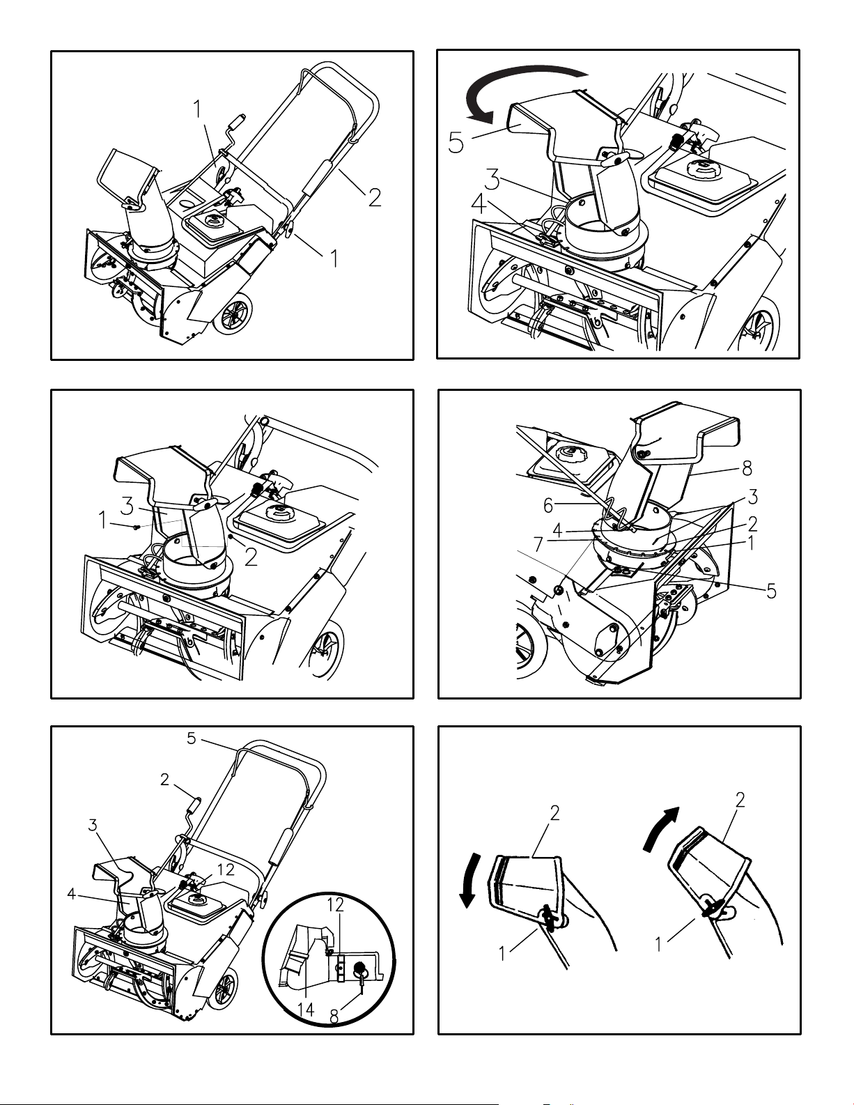
2. (F igu re 1) Loos en the kno bs (1) on ea ch
side of the ha ndle (2).
3. R ais e the upper ha ndle (2)
position.. Hold the upper handle (2) apart to
prevent s cratching the lower ha ndle.
NO TE : Mak e s ure the c ables are no t
cau ght betwe en the upper an d lower
ha ndle.
4. Tighten the kn obs (1).
5. (F igu re 2) C ut and dis card the ca ble tie ( 3)
from the lower end of the chute control r od
(4).
6. Turn the chute defle ctor (5) around toward
the front of the snow thrower.
, remove the wire
to the operating
Ho w T o A ss emble T he L ower C hute
(F igure 3)
For shipping purposes , s ome models a re
shipped with the rea r nut and bolt removed from
the lower chute (3).
tache d, assemble as follows.
1. Use the bolt (1)
parts ba g to attach the lower chute (3).
2. Tip the lower c hute (3)
hole in the chute ring is aligned with the hole
in the lower c hute (3).
3. Attach the lower c hute (3)
and nut (2).
If the lower chute is not a t-
and nu t (2)
Make sure the
found in the
backward until the
with bolt (1)
nut (2)
is tight.
Ho w T o A ss emble
The C hute C ontrol R od
1. R emove the cotter pin (1),
and wave was her (3)
chute c ontrol rod (4). DO N OT DIS C AR D.
2. Mount the end of the c hute c ontrol ro d (4)
through the hole in the control rod bra cket
(5). Ma ke sure the worm gear (6)
with the notc hes (7)
(8).
3. F asten the chute contro l r od (4)
contro l r od bracket (5)
flat was he r (2),
4. R otate the c hute c ontrol rod (4)
and counterclockwise. Make sure the dis cha rge chute (8)
a nd
(F igure 4)
flat was he r (2),
from the end of the
dis charge c hute
in the
cotter pin (1),
with
wave wa sher (3).
rotates freely
.
is aligned
to the
clockwise
Ho w T o P repare The E ngine
WA RNING : F ollo w the en gine
ma nufa cturer’ s ins tructions for th e
type of fuel and o il to us e. A lways
us e a s afety fuel c onta iner
when adding fuel to th e engine.
When ins ide an e nclos ure, do not fill the
fuel tank. B efore you add fuel ,
s top th e engine. L et the e ngin e cool for
s eve ral minutes .
S ee the engine manufacturer’s instructions for
the type of fuel and oil to us e. B efore you us e
the unit, read the information on safety
tion, ma intenance, and s torage.
NO TE : E ngine hor sepo wer ratings ma y var y
by en gine adju stments , m anufacturing v ari-
an ces , altitude, atmos pheric c onditions , fu el
an d m aintenance.
T he 4-cycle engine used in this s now thrower
requires 4-cycle motor oil in the cra nk ca se.
Use
a quality synthetic 5w-30 or10w-30 oil.
. Do not s moke
, opera-
B efore Y
Before you operate your new s now thrower
please review the following checklist:
.
Make sure a ll assembly instructions have
been completed.
.
Make sure the discharge chute rotates freely
.
Make sure that no loos e pa rts remain in the
carton.
As you lea rn how to properly use the s now
thrower, pa y extra attention to the following important items .
.
Make sure the engine c rank case is filled with
the correct amount and type of motor oil.
.
Become familiar with the loca tion of all
controls a nd unders tand their function.
.
Before s tarting the engine, ma ke sure all
controls operate correctly
ou Operate
.
,
.
OM6100
9
Page 10

OP E R AT ION
NO TE : Illus trations begin on page 3.
K now Your S now T hrower
R ead this Instruction B ook and safety rules before operating the snow thrower. C ompare the
illustration with your snow thrower to familiarize
yours elf with the location of va rious controls a nd
adjus tments.
C rank As s embly (2)- C hanges the direction of
the dis charge chute.
C hute Defle ctor (3)snow is thrown.
Dis charge C hute (4)snow is thrown.
Auger Dr iv e L ev er (5)the a uger
Ignition K ey (8) -
to the
R ecoil S tarter Handle(12)start the engine.
C hoke C ontr ol(14)- U se to s tart a cold engine.
which propels the snow thrower
on position to s tart the engine.
C hanges the dis tance the
C hanges the direction the
Mus t be
(F igure 5)
S tarts and stops
.
inserted and turned
Us e to manua lly
WA RNING : T he operation o f a ny
s now thr ower c an res ult in
foreign obje cts being thrown
into the eyes , whic h can res ult in
s eve re eye damage. Always wear s afety
glas s es o r ey e s hields wh ile operating
the s now thrower .We r ecommend
s tand ard s afety glas s es o r us e a wide
vis ion s afety ma sk ov er y our glas s es .
Ho w T o S top Dis charging S now
(Figure 5)
1. To stop discharging snow, relea se the au ger
drive lev er (5).
2. To stop the engine, turn the ignition key (8)
to the off position.
Ho w T o
1. Hold the auger drive le ver (5)
2. To go forward, raise the handle (2)
3. To stop, release the a uger drive le ver (5).
NO T E : If the aug er c ontinues to r otate,
s ee “ How To
C able” in the S ervice a nd A djus tments
s ection.
Mov e F orward
ha ndle (2). T he auger will begin rotating.
the r ubber auger blades (1)
ground. Maintain a firm hold on the han dle
(2) as the snow thrower starts to move forward. Guide the s now thrower by moving the
ha ndle (2) either left or right. Do not a ttempt
to push the snow thrower with eccessive force.
Adjus t T he A uger C ontrol
(F igure 7)
aga inst the
to allow
to contact the
Ho w T o S tart A C old E ngine
1. F ill the fuel tank with a fres h, clea n fuel
Make sure the
2.
is in the disengaged (released) pos ition.
3. Insert the ignition key (8) and turn to the on
position.
4. Move the choke control (14)
pos ition.
5. (R ecoil S tar t) R apidly pull the
ha ndle (12). Do not allow the rec oil s tarter
ha ndle (12) to snap back. S lowly return the
recoil s tar ter handle ( 12).
6. If the engine does not s tart in 5 or 6 tries ,
S ee the “Trouble Shooting C hart” Ins tructions.
7.
W hen the engine runs s moothly move the
cho ke c ontrol (14)
au ger drive lev er (5)
(F igure 5)
recoil s tar ter
to the R UN
to the C HOKE
position.
Ho w T o C ontrol
The Dis charge Of T he S now
WA RNING : Never direct the dis charg e of s now towar d bys tander s.
WA RNING : A lway s s top the engine
before unclogging the dis charge
before leav ing the s now thr ower.
1. (Figure 5)
2. (Figure 6) Loosen the wing knob (1) on the
3. Move the c hute de flec tor (2) up for more
4. Tighten the win g kn ob (1).
Ho w T o T hrow S now
1. E ngage the auger drive lev er (5).
2. To stop throwing s now, release the a uger
chute o r the auger hous ing a nd
cha nge the dis charge direction of the snow.
Turn the
chute deflector (2).
distance or down for les s distance.
crank as s embly (2) to
(F igure 5)
drive lev er (5).
B efore S tarting T he E ngine
1. B efore you se rvice or s tart the e ngine, fa miliariz e yourse lf with the snow thrower. B e
sure you unders tand the function and location of a ll controls.
2. Make s ure that all fas teners a re tight.
3. Make s ure the fuel tank is filled with the correct ga soline .
4. Make s ure the engine crank case is filled with
the c orrect a mount and type of motor oil.
Become familiar with the loca tion of all con-
5.
trols and understand their function.
6.
Before s tarting the engine, ma ke sure all
controls operate correctly
.
Add T he F uel Mix ture
WA RNING : F ollo w the en gine
ma nufa cturer’s ins tructions fo r the
type of fuel and o il to us e. A lways
us e a s afety fuel c onta iner. Do not s mo ke
when adding fuel to the engine. Wh en
ins ide an enc los ure, do not fill the fuel
tan k. B efore you add fuel, stop the en gine.
L et the en gine c ool for s ev era l m inute s.
(Figure 7) Fill the fuel tank (3)
tion with fresh, clean fuel.
Ho w T o S top T he E ngine
To s top the engine, turn the ignition k ey (8)
the off position. K eep the ignitio n ke y (8)
safe place. The engine will not start without the
ignition key (8).
to the full posi-
(F igure 5)
to
in a
OM6100
10
Page 11

。
NO TE : In temperatu res below 0 F,
allow the e ngin e to war m up for
s eve ral minutes before blowing s now..
WA RNING : Never ru n the engine
indoors or in enclos ed, poorly
ve ntila ted are as . E ngine exhaus t
contains c arbon mo nox ide, an o dorles s
an d dea dly ga s. K eep hands , feet, hair
an d loo se c lothing awa y from any
moving pa rts loc ated on the engine o r
the s now thrower.The tem pera ture of
muffler and near by a rea s may ex ceed
。
150 F . A void thes e
Ho w T o S tart A W arm E ngine
If an engine ha s been running and is s till warm,
leave the choke control (14)
position. If the engine fails to start, follow the
instructions ''How
ar eas .
(F igure 5)
in the
R UN
To S tart A C old E ngine”.
Ho w T o R emove S now or Debris From
The Auger Hous ing
WA RNING : Do not a ttempt to remove s now or d ebris th at ma y become lodged in a uger hou sing
without ta king th e following prec autions .
1. R eleas e the auger dr ive lever (5).
2. R emove the ignitio n key (8).
3. Dis connect the spark plug wire.
4. Do not place your hands in the a uger h ous ing (4) or the dis cha rge chute ( 3). Use a
pry bar to remove any s now or debris.
S now Throwing T
1. T his s now thrower will propel itself forwa rd
when the ha ndle is ra ised enough to caus e
the a uger blades to contact the ground. T he
auge r should s top when auger control bar is
releas ed. If it does not s top, see “How To Adjust The Auger C ontrol C able” in the adjustment s ection.
2. Mos t efficient s now throwing is accomplishe d
when the s now is re moved immediately after
it falls .
3. F or complete s now removal, s lightly ove rlap
ea ch previous path.
4. Whenever pos sible, dis charge the s now
down wind.
5. T he dis ta nce the s now will be discha rged
can be a djusted by moving the dis charge
chute deflector. R aise the deflector for more
distance or lower the deflector for less dis tance .
6. In windy c onditions, lower the chute deflector
to direct the discharge d s now clos e to the
ground where it is less likely to blow into unwanted areas.
(F igure 5)
ips
7. F or safety and to prevent dama ge to the
snow thrower, keep the area to be cleared
free of stones, toys a nd other foreign objects.
8. Do not us e the auger propelling feature when
clearing gravel or crushed rock driveways.
Move the handle down to s lightly ra ise the
auge r.
9. T he forward s peed of the snow thrower is
dependent on the depth and weight of the
snow. E xperience will es tablis h the mos t effective method of us ing the snow thrower under different conditions.
10. After eac h snow throwing job, allow the engine to run for a few minutes . The snow and
accumula ted ice will melt off the engine.
11. C lean the snow thrower after each use.
12. R emove ice, snow a nd debris from the entire
snow thrower. Flus h with water to remove all
salt or other chemicals. Wipe snow thrower
dry.
Dry And A
1. S now up to eight inches deep can be removed rapidly a nd easily by walking at a
modera te rate. For snow or drifts of a greater
depth,s low your pace to allow the discharge
chute to dispose of the snow as rapidly as
the a uger receives the snow.
2. P lan to have the s now discharged in the direction the wind is blowing.
We t P ac ked S now
Move s lowly into wet, packe d s now. If the wet,
packed s now causes the a uger to slow down or
the dis charge chute begins to clog, ba ck off and
begin a series of short back and forth jabs into
the s now. These short back and forth jabs , four
to six inches, will “belch” the snow from the
chute.
ve rage S now
S now B anks A nd Drifts
In snow of grea te r depth than the unit, us e the
same “jabbing” technique described above. Turn
the dis charge chute awa y from the s now bank.
More time will be required to remove s now of
this type than level snow.
OM6100
11
Page 12
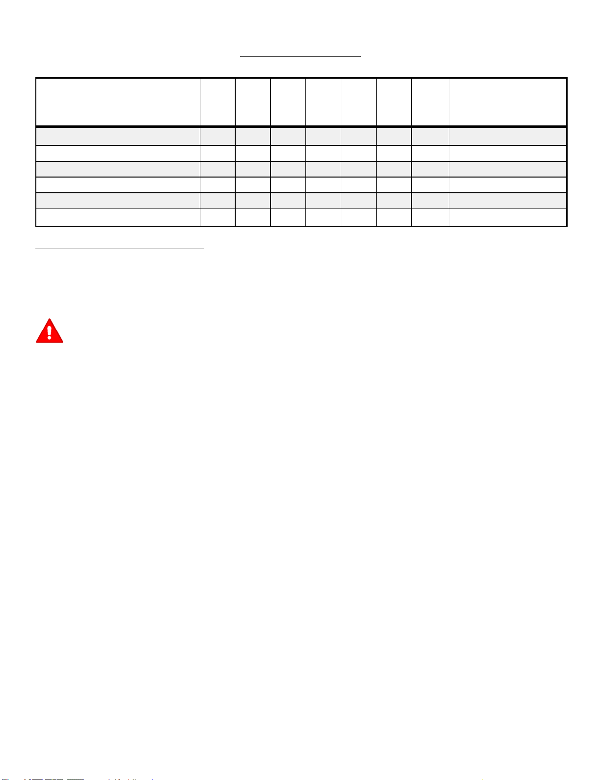
C US TO ME R R E S P ONS IB ILIT IE S
S E RVIC E R E COR DS
Fill in dates a s you
complete regular
s erv ice .
C heck And Tighten All S crews and N uts
C heck Spark P lug
C heck Drive B elt
C heck Fuel
Dra in F uel
Lubricate C hute C ontrol Flange
B efore
E ac h
Us e
MA INTE NA NC E C HA RT
First
Hours
E very
2
Ho urs
E very
5
Ho urs
10
E very
25
Ho urs
E ac h
S ea s on
B efo re
S torag e
S E RVIC E DATE S
MA INTE NA NC E
NO TE : Illus trations begin on page 3.
Us e the following ma intenanc e s ection to keep
your unit in good operating condition. All the
maintena nce information for the engine is in the
engine manufac turer’s ins tructions. B efore you
start the engine, rea d this book.
WA RNING : B efore y ou make an ins pec tion, adjus tment (exce pt
car buretor), o r repair,
the wire from the s park plug .
dis connec t
G enera l R ecommendations
The warra nty on this snow thrower does not cover items that have been subjected to operator
abus e or negligence. To receive full value from
the wa rranty, the operator must maintain the
snow thrower as ins tructed in this manual.
S ome adjus tme nts must be made periodica lly to
properly maintain the snow thrower.
After E ach Us e
C heck for any loose or da maged parts.
T ighte n any loos e fa steners.
C heck and maintain the auger.
C heck controls to ma ke sure they are
functioning properly.
If any parts a re worn or damaged, replac e
immediately.
All adjus tments in the Main tenanc e s ection of
this manua l should be checked at least once
ea ch s eas on.
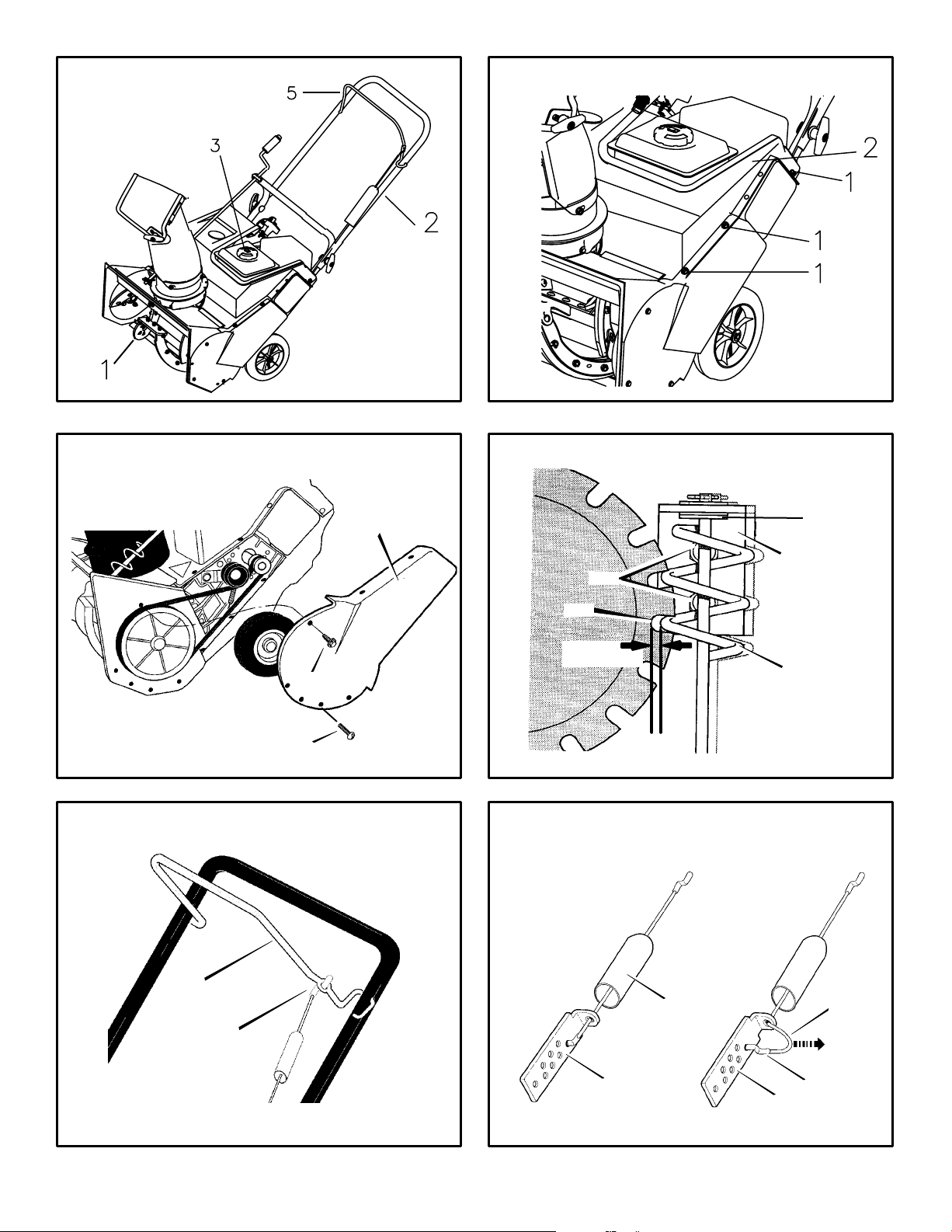
Ho w T o R emove The T
(F igure 8)
1. R emove the five sc rews (1) from the top
cov er (2).
2. R emove the top c over (2).
3. To install the top cover (2),
above steps.
L ubric ation
B efore S torage (Figure 10)
1. Lubricate the
a clinging type of greas e s uch as Lubriplate.
OM6100
clute c ontr ol flange (7).
op C ov er
reverse
the
Apply
Ho w T o A djus t T he C hute Crank
If the chute crank will not rotate fully to the left or
right, a djust as follows.
1. (Figure 10) Loosen nuts (1).
2. Move the c rank adju sting br acke t (2)
allow 1/8 in ch (3mm) c leara nce (3)
between the notch in the
the outer di
3. Tighten the nuts (1).
Ho w
T o
ame te r of the
A djus t T he Auger C ontrol
flange (4) and
worm gear (5).
to
C able
The auger control cable is adjusted at the factory. During normal us e, the a uger control cable
can become s tretched and the a uger drive lever
will not properly engage or dis engage the auger.
1. (F igu re 11) R emove the “ Z” hook (1)
from the
2. (F igu re 12) S lide the c able boo t (3)
cable adjus tment br acke t (4).
3. P ush the bottom of the auger c ontrol cable
(5) through the c able adjus tment brac ket
(4) until the “ Z” hoo k (6) can be removed.
4. R emove the “ Z” h ook (6) from the c able
adjus tment brack et (4).
(6) down to the next adjus tment hole.
5. P ull the a uger c ontr ol c able (5)
the c able adjus tment brac ket (4).
6. P ut the cable boot (3)
jus tment brac ket (4).
7. (F igu re 11) Install the “ Z” hook (1) to the
au ger drive lev er (2).
8. To check the a djustment, start the s now
thrower. Make sure the auger doe s not rotate
when the a uger drive lever is releas ed.
au ger drive lev er (2).
Move the
over the
off the
“ Z ” ho ok
up through
cable ad-
Ho w T o R emove The B elt C over
(F igure 9)
1. T he be lt c over (1)
s crews (2). R emove a ll ten screws.
2. T here are five screws on the front of the belt
cov er (1). Three s crews on the bottom of the
belt c ove r (1).
belt c ove r (1).
3. R emove the belt cover (1).
4. To install the belt c over (1), reverse the
above steps.
NO TE : O ne s crew (3) is s hor ter than the
other s crews . Mak e s ure to ins tall s crew
(3) in the c orrect location.
is fastened with ten
Two s crews on the top of the
12
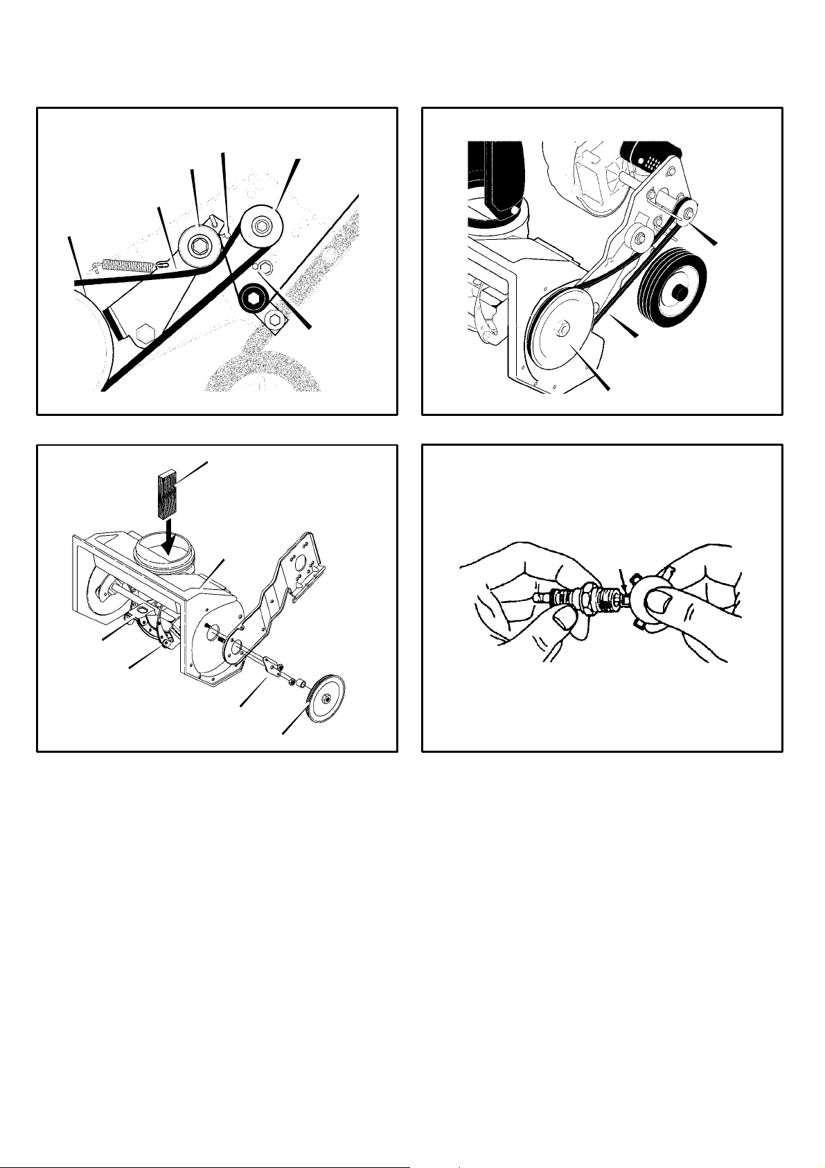
Ho w T o R eplace T he Drive B elt
The drive belt is of s pecial construction and
must be replaced with original factory replacement belt available from your nearest authorized
service center.
1. R emove the belt cover. S ee “How To R emove The B elt C over”.
2. (F igu re 13) R emove the drive belt (1)
the idler pulle y (2).
3. R emove the drive belt (1) from the engine
pulle y (3). B e care ful, not to bend the belt
guides (4).
4. (F igu re 14) R emove the drive belt (1) from
the a uger pulley (5).
5. R emove the old drive belt (1).
6. To install the new drive belt (1),
above steps.
7. Make s ure the driv e belt (1)
erly on the pulleys.
NO TE : W hen the auger contro l lever is
engaged, the belt guide s (4) mus t be
1/16” from th e drive belt (1).
8. Ins tall belt cover. See “How To R emove T he
Belt C over”.
Ho w T o R eplac e T he A uger
1. R emove the belt cover. S ee “H ow To Remove The B elt C over”.
2. R emove the drive belt. S ee “How To R eplace
The Drive Belt”.
3. R emove the a uger pulley (1)
shaft (threads are left hand; turn clockwis e to
remove).
4. To keep the auger (6)
2”x4” piece of wood (2) on the center
paddle (3) to secure au ger (6).
5. R emove the fasteners from the bearing as s embly (4). R emove the bea ring a ss embly
(4) from the au ger hous ing (5).
6. S lide the auger (6)
bly on the right side of the snow thrower.
7. Tip the auger ( 6) enough to allow the
(6) to slide out of the auger hous ing (5).
8. To install auger (6), re verse the a bove s teps .
out of the bearing as sem-
is s eated prop-
(F igure 15)
from the auger
from rotating, s et a
from
reverse the
au ger
Page 13

Ho w T o R eplac e The S park P lug
1. The spark plug and wire is visble on the engine
at the rear of the snow thrower.
2. R emove the spark plug wire.
3. C lean the area around the s park plug base to
prevent dirt from e nte ring the engine when the
spark plug is removed.
4. R emove the spark plug.
5. C heck the spark plug. If the spa rk plug is
cra cked, fouled or dirty, it mus t be replaced .
6. (F igure 16) S et the gap between the elec-
trodes of the new s park plug at . 030 inch. Ne xt,
install the spark plug in the cylinder head and
firmly tighten. R ecommended torque is 18 to
20 foot pounds .
Ho w T o P repare The S now T hrower For
S torage
WA RNING : Do not remov e ga soline
while in side a building, near a fire ,
fumes c an caus e an explo sion or a fi re.
or while y ou s mo ke. G as oline
Dra in the fuel tank. Do not s iphon by mouth.
1.
Let the engine run until it is out of gasoline.
2.
3. R emove the s park plug from the cylinder.
P our one ounce of oil into the c ylinder. S lowly pull the re coil-start grip s o that the oil will
protect the cylinder. Ins tall a new s park plug
in the cylinder.
4. T horoughly clean the snow thrower.
5. Lubricate a ll lubrica tion points. S ee the Maintenanc e s ection.
6. B e s ure that all nuts, bolts and screws are
securely fas tened. Inspect a ll vis ible moving
parts for damage, breakage a nd wear. R eplace if necessa ry.
7. C over the bare metal parts of the blower
housing a nd a uger with s pray rust preve nta tive lubricant.
8. P ut the unit in a building that has good ventilation.
9. If the ma chine must be stored outdoors ,
block up the snow thrower to be s ure the entire ma chine is off the ground.
10. Cover the s now thrower with a suitable protective cover that does not re ta in moisture.
Do not us e plastic.
Ho w T o Order R eplacement P arts
The replacement pa rts are shown either on the
back pages of this Ins truction B ook or in a
separate Pa rts List B ook.
Us e only ma nufacturer’s a uthorized or approved
replacement parts.
or acces sories not s pecifica lly recommended
for this unit. In order to obtain
Do not use attachments
proper replacement parts you mus t s upply the
model number (s ee name plate).
R eplac ement parts, e xcept for the engine,
transmission, transaxle or differential, are
available from the store where the product was
purchased, a service shop recommended by the
store or from Ardisam
All Ardis am contact info(see pa ge 6) .
, Inc. 1-800-345-6007
.
OM6100
13
Page 14

TR OUB LE S HOOT ING C HA RT
TR OUB LE C A US E C O R R E CTION
Difficult s tarting Defective spark plug. R eplac e s park plug.
Wa ter or dirt in fuel system. Us e carburetor bowl drain to flush a nd refill with
E ngine ru ns erratic Blocked fuel line, empty gas tank, or s tale
E ngine s talls Unit running on C HOKE . S et choke lever to R UN pos ition.
E ngine ru ns erratic;
L os s of power
E xc es siv e vibration Loose parts: dama ged impeller S top engine immediately a nd disc onnect s park
Un it fails to propel its elf Drive belt loose or damaged. R eplac e drive belt.
Un it fails to dis c harge s now Auger drive belt loos e or dama ged. Adjus t auger drive belt; replace if damage d.
gas oline
Wa te r or dirt in fuel system. Us e carburetor bowl drain to flush a nd re fill with
Auger control cable not adjusted correctly. Adjus t auger control ca ble.
Dis charge c hute c logged. S top engine immediately a nd disc onnect s park
Foreign object lodged in auger S top engine immediately a nd disc onnect s park
fres h fuel.
C lean fuel line; check fuel s upply; add fres h
gas oline
fres h fuel.
plug wire. T ighte n all bolts and make all
neces sary repairs. If vibration continues, have
the unit s erviced by a competent repairman.
plug wire. C lean dis charge chute and inside of
auge r housing.
plug wire. R emove object from a uger.
OM6100
14
Page 15

Part List - Model 6100
15OM6100
Page 16
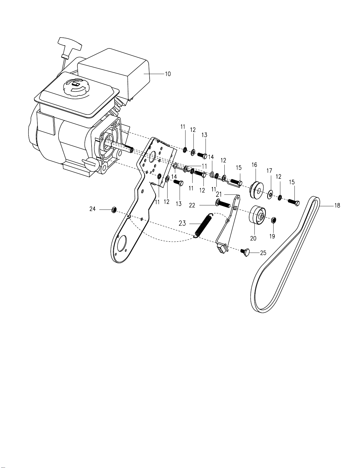
MODE L 6100 R E PAIR PA R T S
Key No. Part No. Description
10 6105 ENGINE
11 71071 WASHER FLAT
12 71060 WASHER
13 181595 BOLT,5/16-24X.75
14 6124 GUIDE,BELT
15 910828 BOLT,5/16-24X1.00
16 338849 PULLY,ENGINE
17 25840 WASHER,BELLEVILLE
18 37X132 BELT V 3L 34.8”
19 6115 NUT
20 48924 PULLEY,IDLER
21 1501013 ASSY,IDLER BRAKE
22 45892 BOLT,CARRIAGE
23 6128 SPRING,IDLER BRAKE
24 71391 NUT,5/16-18
25 333594 BOLT
E NG INE AS S E MB LY
OM6100
16
Page 17
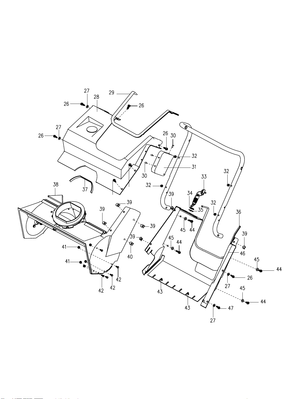
MODE L 6100 R E PAIR PA R T S
FR AME COMP ONE NT S AS S E MB L Y
OM6100
17
Page 18

MODE L R E PA IR P AR TS
Key No. Prat No. Description
26 313685 SCREW,1/4-14X.75
27 71067 WASHER,FLAT.281X.63X.065
28 6131 COVER,TOP
29 6133 CUSHION
30 902937 RIVET
31 58046 COVER,SIDE
32 73826 NUT,1/4-20
33 6116 ASSY,SWITCH
34 300193 NUT,5/8-32 ACC
35 313683 WASHER
36 6133 CUSHION
37 55380 SEAL,STRIP CHUTE&GAS SEAL
38 55379 SEAL,FOAM
39 578109 NUT,1/4-20SPEED J TYPE
40 578107 NUT,1/4-20-20 TINN
41 312300 NUT,#10-24
42 12342 SCREW,10-24X.50
43 26X29 SCREW,10-14X.63
44 313674 SCREW,1/4-20X1.25
45 71067 WASHER,FLAT.281X.63X.065
46 6130 COVER,BOTTOM
47 313686 SCREW,1/4-20X.50
TOP COV E R AS S E MB LY
OM6100
18
Page 19
MODE L 6100 R E PA IR P AR TS
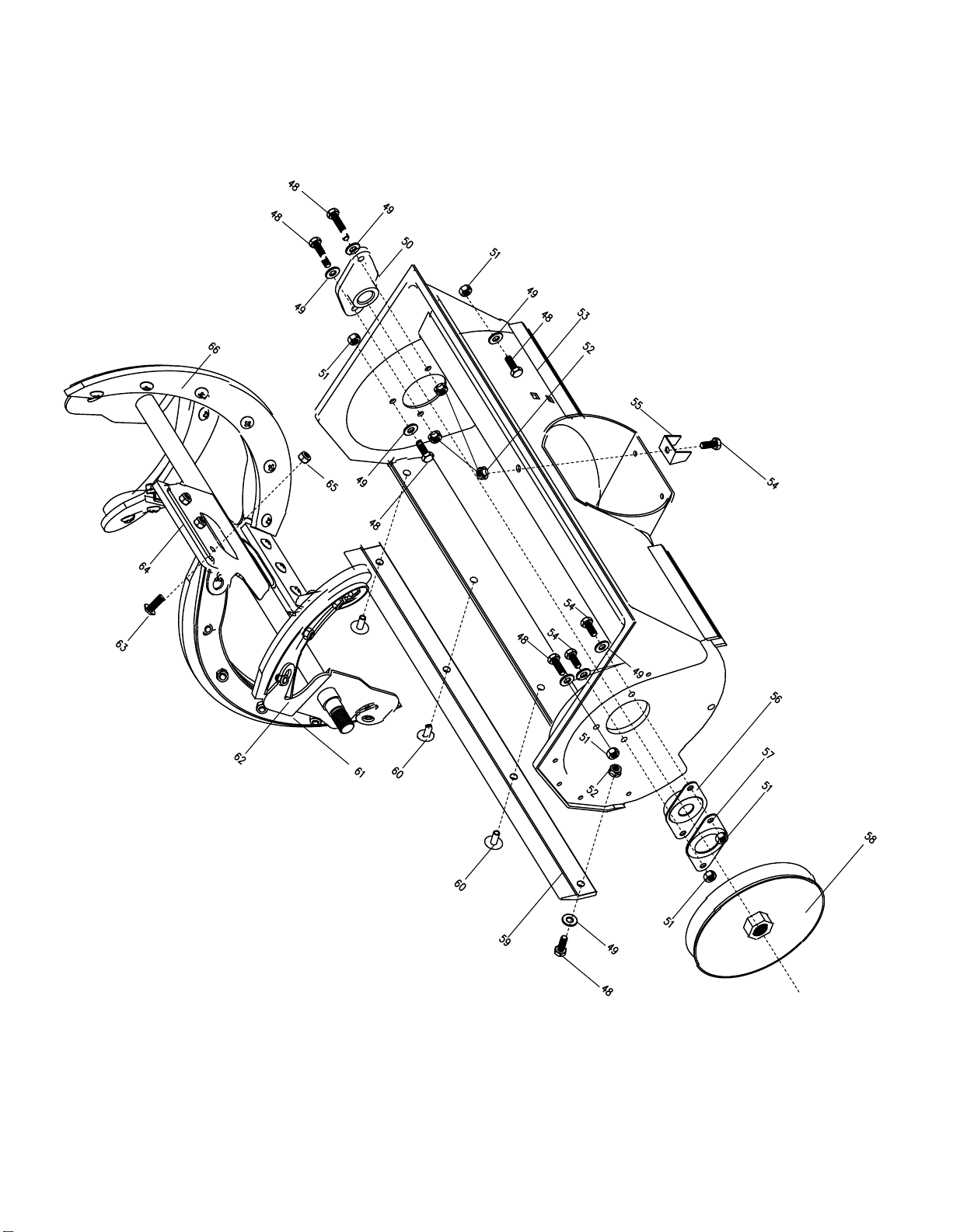
AUG E R HOUS ING
OM6100
19
Page 20

MODE L 6100 R E P AIR P AR T S
AUG E R HOUS ING
Key No. Part No. Description
48 302628 SCREW,1/4-20X.75
49 71067 WASHER,FLAT
50 577023 BEARING,FLANGE
51 73826 NUT,1/4-20
52 15X143 NUT,HEX1/4-20YZ
53 6125 HOUSING,ASSY
54 579052 SCREW,1/4-20X.63
55 331126 BRACKET,STOP
56 583459 BEARING&PLATE ASSY
57 334287 PLATE,RETAINER
58 338965 PULLEY
59 334031 BLADE,SCRAPER
60 577707 RIVET,OVSET
61 302552E701 AUGER&BLADE SUPPORT
62 6126 AUGER,ASSY
63 6127 BOLT,1/4-20X.75
64 335992 BLADE,CENTER
OM6100
65 780029 NUT,1/4-20HEX NY LOCK
66 302565 BLADE,AUGER
20
Page 21
MODE L 6100 R E P AIR P AR TS
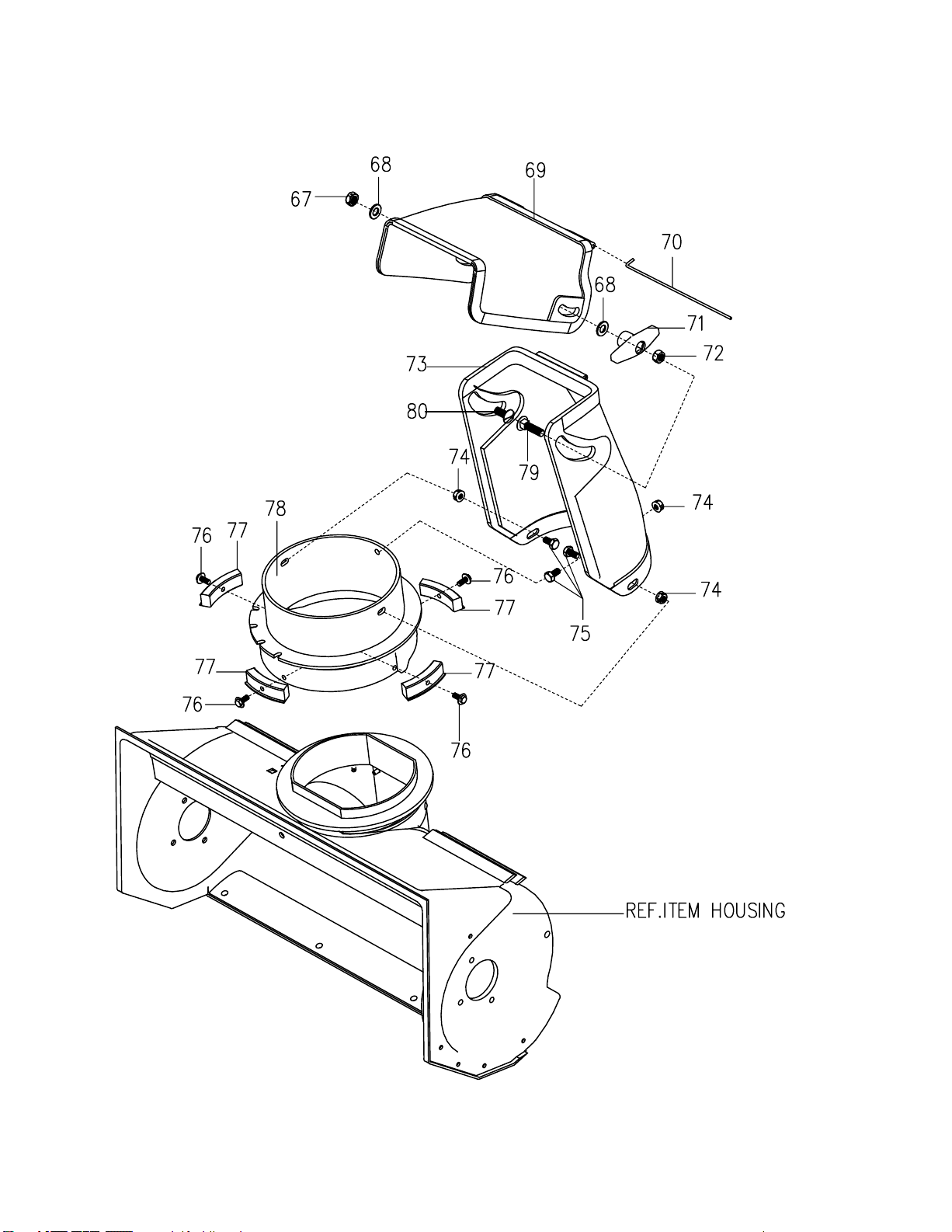
DIS C HA R G E C HUTE
OM6100
21
Page 22

MODE L 6100 R E PAIR PAR TS
Key No. Part No. Description
67 71391 NUT,HEX 5/16-18
68 71071 WASHER,FLAT.349X.69X.066
69 325849 CHUTE,UPPER
70 308931 WIRE,HINGE
71 57171 KNOB,T
72 71037 NUT,HEX5/16-18
73 334234 CHUTE,LOWER
74 15X143 NUT,1/4-2YZ
75 313686 SCREW 1/4-20X0.50
76 711752 SCREW,#10X.50
77 5777021 GUIDE,CHUTE
78 333859 RING,CHUTE
79 302843 BOLT,CARRIAGER,
5/16-18X1.25
80 578088 SCREW,5/16-18X.75
DIS C HA R G E C HUTE
OM6100
22
Page 23
MODE L 6100 R E PAIR PA R T S
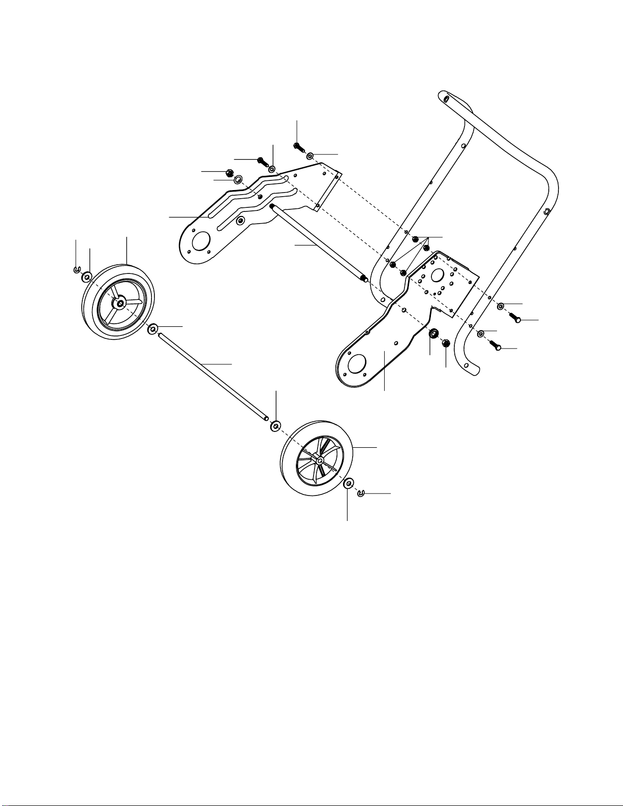
WHE E LS A S S E MB LY
87
88
88
90
88
87
88
87
85
86
91
81
82
87
86
85
84
83
87
82
92
82
83
81
82
Key No. Part No. Description
81 577598 RING,RET E
82 583409 WASHER,FLAT .391X1.00X.125
83 760713 TIRE&RIM
84 760272E701 FRAME SIDE SUPPORT RH
85 71063 WASHER,HVSPTLK
86 71044 NUT,3/8-16 REGHEX
87 313674 SCREW,14-20X1.25
88 71067 WASHER,FLAT
89 760169 ROD,SUPPORT
90 73826 NUT,1/4-20
91 6121 FRAME SIDE SUPPORT LH
92 313678 AXLE SHAFT
OM6100
2
3
Page 24
MODE L 6100
93
94
95
R E PAIR PA R T S
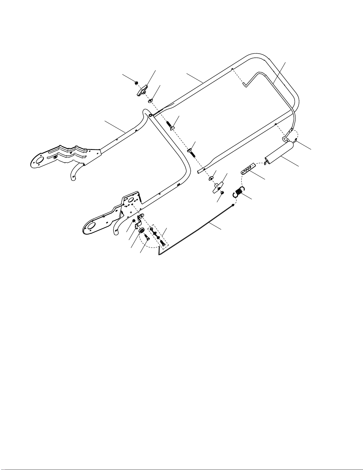
HANDL E AS SE MB LY
99
97
96
98
98
100
96
95
102
103
94
R E F E NG INE
108
107
106
105
104
Key No. Part No. Description
93 6120E701 HANDLE,LOWER
94 71037 NUT,5/16-18
95 57171 KONB,T3.00WD
96 311936 WASHER,FORM
97 313489E701 UPPER HANDLE
98 337584 BOLT
99 313308E701 BAIL,CONTROL
100
760774 CABLE,UPPER
101 308146 BOOT,CLUTCH SPRING
102 313441 BRACKET,CABLEADJ
103 313471 SPRING,EXTENSION
104 760773 CABLE,LOWER CONTEOL
105 712234 BOLT
106 39298 PULLEY
107 761486E701 BRACKET,CABLE
108 73826 NUT,1/4-20
101
OM6100
2
4
Page 25
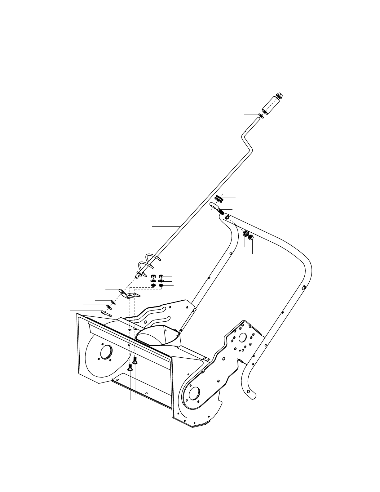
MODE L 6100
R E PAIR PA R T S
C HUTE R OD AS S E MB LY
120
119
118
121
110
111
112
113
122
117
123
124
116
115
114
OM6100
109
109
25
Page 26

MODEL 6100
Key No. Part No. Description
109 340720 BOLT,CARRIAGE 5/16-18X.75
110 71082 PIN,COTTER
111 71072 WASHER,FLAT.406X.81X.066
112 313431 WASHER,CURVED SPRING
113 333946E701 BRACKET,CHUTE ROTATE
114 71071 WASHER,FLAT.349X.69X.066
REPAIR PARTS
CHUTE ROD ASSEMBLY
115 71060 WASHER.328X.60X.09
116 71037 NUT,HEX 5/16-18
117 337941 ROD,ASSY UPPER CHUTE CONTROL
118 71072 WASHER,FLAT.406X.81X.066
119 57082 KNOB,SLEEVE
120 331532 NUT,PUSH
121 6118 GROMMET,EYE BOLT
122 313712 BOLT,EYE 3/8-16X2.00
123 71062 WASHER
124 71045 NUT,HEX JAM 3/8-16
OM6100
26
Page 27

 Loading...