

Page 1
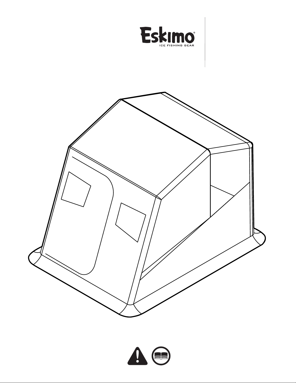
Operator's Manual
GAS/OIL
RATIO
50:1
Original Operating Instructions
FlipMo™ 2
Inferno
Flip-Style Sled Shelter
Get parts online at
www.GetEskimo.com
15649
ECN # 9837
Rev. 1 06/11/2013
© Copyright 2013 Ardisam, Inc.
All Rights Reserved.
Page 2
Operator's Manual
ESKIMO® FlipMo™ 2 Inferno
INTRODUCTION
Eskimo® Ice Shelters are engineered with the ice fisherman in mind. We make quality and durability our priority, and we appreciate
your purchase of one of our ice shelters. Follow these simple instructions and your ice shelter will provide you many years of troublefree pleasure. Save these instructions for future reference. If for any reason you have a problem with your product, DO NOT return
to the retailer, contact the Eskimo® customer service department at 1-800-345-6007 or by email at [email protected] for
assistance. Congratulations on your investment in quality. Save these instructions for future reference. Ardisam, Inc reserves the
right to change or alter this manual without notice.
CONTENTS
Introduction ....................................................................................................................................................................................................................................... 2
Registration ........................................................................................................................................................................................................................................2
Important Safety Precautions ...................................................................................................................................................................................................... 3
Assembly ......................................................................................................................................................................................................................................... 4-8
Shelter Set-Up and Take Down Instructions ........................................................................................................................................................................... 8
Long-Term Storage ..........................................................................................................................................................................................................................8
Parts .................................................................................................................................................................................................................................................9-10
Warranty ............................................................................................................................................................................................................................................11
Bolt Identication Chart ...............................................................................................................................................................................................................12
REGISTRATION AND SERVICE
Record the product model number and serial number in the space provided for easy reference when ordering parts or requesting
technical support. You can register your warranty online by visiting www.geteskimo.com, or by mailing it to: Ardisam, Inc., 1160
Eighth Avenue, Cumberland, WI 54829. For service questions, call our customer service department at (800) 345-6007 Mondays
through Fridays from 8 a.m. to 5 p.m. CT. Warranty is valid only if the completed registration card is received by Ardisam, Inc. within
30 days of purchase.
OWNERSHIP RECORDS
Place of Purchase:
Place of Purchase Address:
City: State/Province: Zip Code/Postal Code:
Model Number: Serial Number (found next to warning tag):
Date of Purchase:
Notes:
2
Check for parts online at www.GetEskimo.com or call 800-345-6007 M-F 8-5 CDT
Page 3
IMPORTANT SAFETY PRECAUTIONS
This shelter is made with flame resistant fabric which meets
CPAI-84 specifications. It is not fire proof. The fabric will burn if
left in continuous contact with any flame source. The application
of any foreign substance to the shelter fabric may render the
flame resistant properties ineffective.
Fuel-based heat sources burn oxygen and emit carbon monoxide
(an odorless, colorless, poison gas). Breathing carbon monoxide
can cause headaches, drowsiness, nausea, dizziness, confusion
and eventually death. Use caution with heaters. Be sure you
have adequate fresh ventilation, including open windows and
doors. All vents must be opened when using fuel-based heaters
in your shelter.
• Donotusecandles,matchesoropenflamesofanykindin
or near an ice shelter.
• Donotcookinsidetheshelter.
• Exerciseextremecautionwhenusingfuel-powered
lanterns or heaters inside a tent. Use battery-operated
lanterns whenever possible.
• Donotrefuellamps,heatersorstovesinsideatent.
• Ifyouarefishingandfallingasleepintermittently,turnoff
all lanterns and heaters.
• Donotsmokeinshelter.
Operator's Manual
ESKIMO® FlipMo™ 2 Inferno
WARNING
READ, UNDERSTAND AND FOLLOW ALL ASSEMBLY,
SAFETY, SETUP & USE INSTRUCTIONS PROVIDED
BEFORE USE. FAILURE TO FOLLOW ALL WARNINGS
AND INSTRUCTIONS COULD RESULT IN SERIOUS
INJURY OR DEATH.
DO NOT USE OPEN FLAME HEATERS IN YOUR ICE
SHELTER.
WARNING: KEEP ALL FLAME AND HEAT SOURCES AWAY
FROM THIS TENT FABRIC. THIS TENT IS MADE WITH
FABRIC THAT MEETS CPAI84 SPECIFICATIONS FOR
FLAME RESISTANCE. IT IS NOT FIRE PROOF. THE FABRIC
WILL BURN IF LEFT IN CONTINUOUS CONTACT WITH ANY
FLAME SOURCE.
DUE TO TRAFFIC ON LAKES, ICE FISHING CAN BE
HAZARDOUS AT NIGHT. IF YOU CHOOSE TO FISH AT
NIGHT OR IN CONDITIONS WITH POOR VISIBILITY, BE
SURE TO TAKE PRECAUTIONS.
NEVER LEAVE THE ICE SHELTER UNATTENDED.
SECURELY ANCHOR THE ICE SHELTER TO THE ICE IN
HIGH WIND CONDITIONS.
• Donotstoreflammableliquidsinsideoftheshelter
.
Check for parts online at www.GetEskimo.com or call 800-345-6007 M-F 8-5 CDT
3
Page 4
Operator's Manual
ESKIMO® FlipMo™ 2 Inferno
ASSEMBLY INSTRUCTIONS
Tools needed – (2) 7/16” wrenches, a Phillips head screwdriver,
rubber mallet (optional), and a cordless drill (optional).
Assembly Note: This ice shelter should be assembled in
a garage or basement setting due to the time and length
of assembly. Identify and familiarize yourself with all
parts and hardware before assembly. Allow 1-3 hours for
assembly.
Assembly Note: The use of a cordless drill with socket will
make assembly of your ice shelter much quicker. Be sure to
set the drill speed on low so you do not over tighten any nut
and bolt combination.
Assembly Note: If a tracking kit is purchased with the
shelter it should be mounted to the sled before assembly
of the ice shelter for convenience.
Important Assembly Tip: Do NOT fully tighten any nut and
bolt combination until instructed in later notes. This will
help hole alignment of all parts.
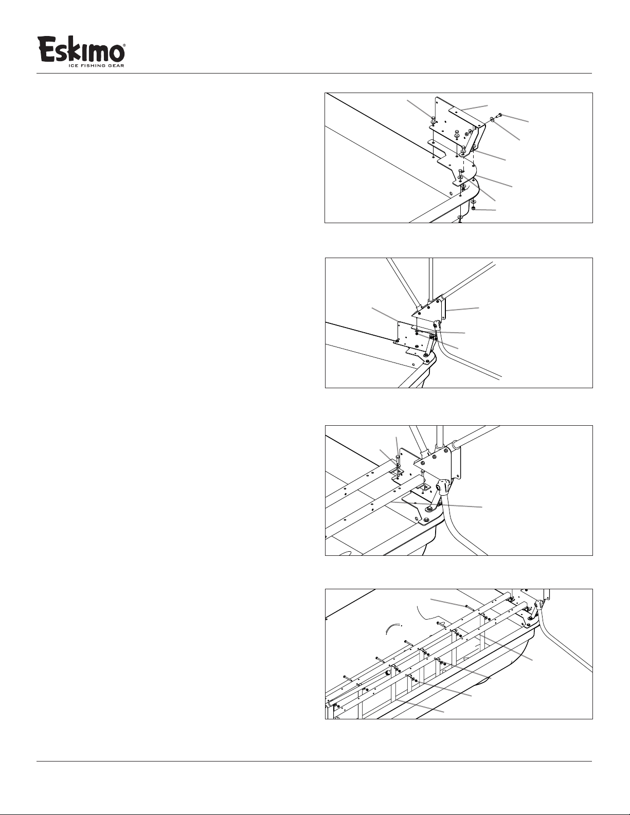
1. Attach the Hinge Riser A (68052) and corner mount plate
(11599) to the tub using (4) ¼-20 X 1” bolts, (8) ¼” washers
and (4) ¼-20 nylock nuts. Align the hole pattern on the
plate corner mount (11599) with the left hinge assembly
(69307L) to the matching hole pattern on the sled. Insert
bolts starting with hole #1 (using a ¼-20 x 1” bolt) then move
on to #2, #3 and #4, tightening bolt/nut combinations as
you go. SEE FIGURE 1
Note: Hole 3 and 4 will be used to attach the versa seating
system. Do not fully tighten these bolts as they will need to
be taken o again for a later step.
2. Repeat step 1 on the opposite side using Hinge Riser B
assembly (68053). SEE FIGURE 1
¼-20 X 1” bolts
FIGURE 1
Hinge Riser A
FIGURE 2
¼-20 X 1” bolt
¼” washer
Hinger Riser A
¼-20 X ¾” bolt
¼” washers
#4
#3
#5
(not shown)
#2
#1
¼” washer
¼-20 nylock nut
#4
#3
hinge support brace
corner mount plate
¼-20 X ¾” bolt
¼-20 nylock nut
Hinge Assembly A
seat rail
(2) ¼-20 x ¾” bolts
Note:
not shown
3. Attach the (2) hinge support braces (11203) to both the
Hinge Riser A (68052) and Hinge Riser B (68053) using
(4) ¼-20 x ¾” bolts, (4) ¼” washers, and (2) ¼-20 nylock
nuts. First attach the hinge support brace (11203) to hole
#5 on the corner mount plate (11599). SEE FIGURE 1
Note: If the hole alignment is o or looks too far apart,
rotate the hinge support brace and try again. This part will
only bolt on one way.
4. Attach the Hinge Assembly A (68141) to Hinge Riser A (68052)
using (2) ¼-20 X ¾” bolts, (4) ¼-20 nylock nuts and ¼” washers.
SEE FIGURE 2
5. Repeat step 3 on the opposite side using the Hinge Assembly
B (68142). SEE FIGURE 2
Note: Be sure the hinge assembly is on correctly with the
high side of the hinge placed towards the front of the sled.
4
Check for parts online at www.GetEskimo.com or call 800-345-6007 M-F 8-5 CDT
FIGURE 3
¼-20 X 2¼” bolt
seat rail
¼” washer
¼-20 nylock nut
vertical frame support
FIGURE 4
Page 5
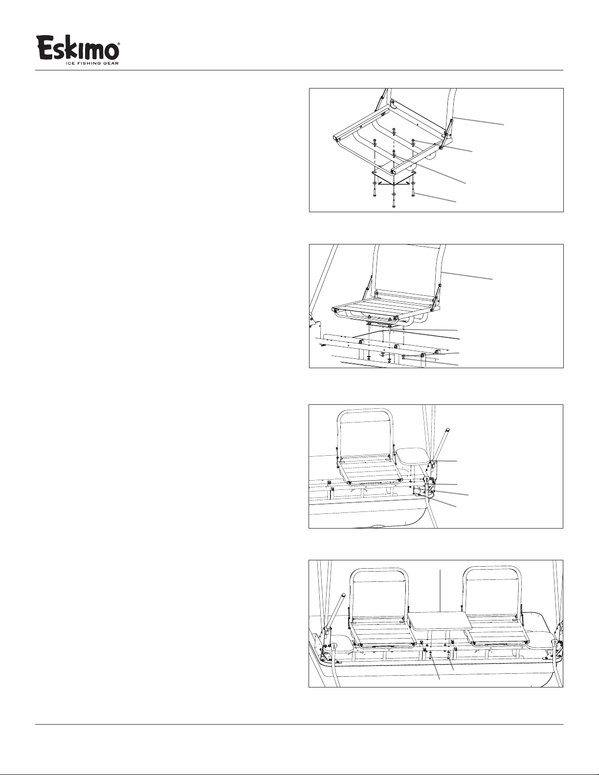
6. Attach the seat rail (14818) through holes #3 and #4. As
mentioned earlier you will need to remove the bolts in this
step to t the seat rail (14818) to the holes. Replace the
hardware and tighten. SEE FIGURE 3
7. Attach the (4) vertical frame supports (11305) by locating
the correct holes in the seat rail (14818) that are called out in
Figure 4. Using (8) ¼-20 x 2¼” bolts, (16) ¼” washers and (8)
¼-20 nylock nuts. SEE FIGURE 4
8. Tighten all hardware used to complete this portion of
assembly instructions.
Note:
(SEAT FABRIC
HIDDEN FOR
ASSEMBLY
CLARIETY)
FIGURE 5
Operator's Manual
ESKIMO® FlipMo™ 2 Inferno
versa seat
¼-20 nylock nut
¼” washer
¼-20 X 1½” bolt
VERSA SEAT AND ACCESSORY TABLE INSTALLATION
9. Locate the included (2) Versa Seats (15004), (2) small parts
bags (15752) and the (2) swivels (15016). Attach (1) swivel
(15016) to (1) Versa Seat (15004) using (4) ¼-20 x 1½” bolts,
(8) ¼” washers and (4) ¼-20 nylock nuts. Repeat this step to
assemble the other seat/swivel combination SEE FIGURE 5
10. To attach the seat/swivel assembly, from Step 9, to the seat
rail (14818), use the remaining hardware found in the small
parts bag (15752) -- (4) ¼-20 x 1½” bolts, (8) ¼” washers and
(4) ¼-20 nylock nuts. Repeat this step to assemble the other
seat/swivel assembly to the seat rail (14818). SEE FIGURE 6
11. Locate the (2) 12-1/8” x 9-1/8” tables (11331) and the (1) 173/8” x 12-1/2” table. Attach (1) smaller table to the seat rail
(14818) using (2) ¼-20 x 1¼” bolts and (2) ¼” washers. Repeat
this assembly for the other small table. SEE FIGURE 7
12. Using (4) ¼-20 x 1¼” bolts and (4) ¼” washers, attach the large
table (15646) to the seat rail (14818). SEE FIGURE 8
13. Tighten all hardware used to complete this portion of
assembly instructions.
versa seat
¼-20 X 1½” bolt
¼” washer
¼-20 nylock nut
FIGURE 6
12-1/8” x 19-1/8” table
seat rail
¼” washer
¼-20 X 1¼” bolt
FIGURE 7
FIGURE 8
Check for parts online at www.GetEskimo.com or call 800-345-6007 M-F 8-5 CDT
17-3/8” x 12-1/2” table
¼-20 X 1¼” bolt
¼” washer
5
Page 6
Operator's Manual
ESKIMO® FlipMo™ 2 Inferno
SHELTER FRAME/SKIN INSTALLATION
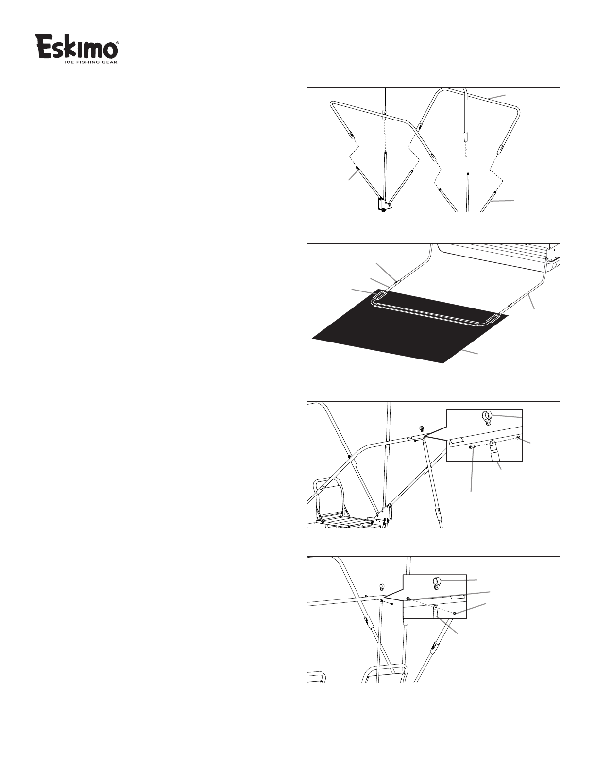
14. Insert the 3 upright poles from each hinge (68141/68142) into
the (3) Top Cross Braces (68131). Push the snap button inward
to allow the Top Cross Brace to slide over the upright hinge
poles. Adjust the Top Cross Braces on the hinge to be in the
transport position (lowest collapsed height). SEE FIGURE 9
15. Unfold the skin and locate the Eskimo® logo near the zippered
door, which is in the front of the sled. With the outer part of
the shelter skin lying facing down, locate the (3) pole sleeves
on the bottom front, right side, and left side of the shelter
skin. Slide the Lower Cross Brace (68129) through the (3) pole
sleeves. SEE FIGURE 10
16. Insert a hinge “J-Pole” from each hinge (68141/68142) into
the assembled lower frame (68129) with the skin attached to
the frame. Push snap button inward to allow the Lower Cross
Brace to slide over the (J-Poles) attached to the hinges. SEE
FIGURE 10
17. Attach the door spreader pole assembly (15702) using a ¼-20
x 3/4” bolt and ¼-20 nylock nut. To attach the spreader poles
the hardware should all be ¼-20 x 3/4” bolts and ¼-20 nylock
nuts. This hardware is already attached to the assembly and
will need to be removed for proper installation. Push the
pole clamp (15705) onto the front upper cross brace and
reassemble (15702), the reassembly will fasten the door
spreader pole to the front upper cross brace. After assembly
fully extend the door spreader pole and clip to the lower
cross brace. The front upper cross brace should now be selfsupporting. SEE FIGURE 11
18. To attach the rear spreader (15703) pole follow the assembly
instructions above for the previous spreader pole attachment.
Once the rear pole assembly is attached to the rear upper
cross brace insert the plastic stud into the hole centered on
the rear lip of the sled. This assembly will make the rear upper
cross pole self-supporting. SEE FIGURE 12
top cross brace
snap button
upright pole
FIGURE 9
snap button
lower cross brace
fabric sleeve
hinge J-pole
skin
FIGURE 10
pole clamp
¼-20
nylock nut
door spreader
pole assembly
¼-20 x 3/4” bolt
FIGURE 11
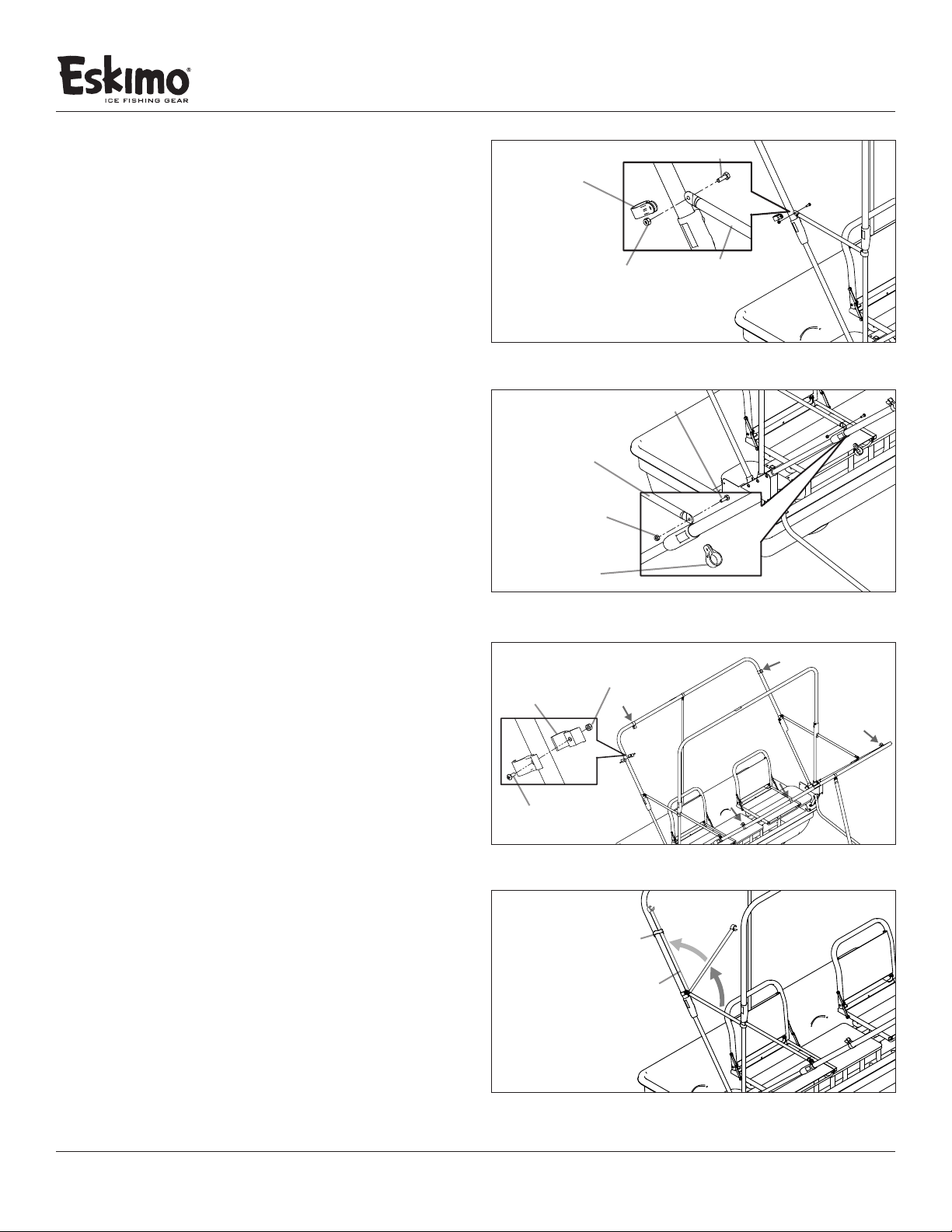
19. Attach the rear side spreaders (15706) to the rear upper cross
brace. The attachment is similar to the previous spreader pole
assemblies. Repeat assembly for other side also attaching to
the rear upper cross brace. Once both spreader poles are in
place clip them to the middle upper cross brace. This will make
the middle upper cross brace self-supporting. SEE FIGURE
13
20. Attach the remaining front side spreaders (15700) to the front
upper cross brace. Assembly is similar to previous assembly
at Step 17. Once both spreader poles are in place clip them to
the middle upper cross brace. This will complete the spreader
pole installation. SEE FIGURE 14
6
Check for parts online at www.GetEskimo.com or call 800-345-6007 M-F 8-5 CDT
pole clamp
¼-20 x 3/4” bolt
¼-20 nylock nut
door spreader
pole assembly
FIGURE 12
Page 7
Operator's Manual
ESKIMO® FlipMo™ 2 Inferno
21. In the parts box there is a bag of pole retention clips. These
clips will be used in the “stow and go” position of the spreader
poles. The installation of the pole retention clips involves (2)
clip retainers (15708), (1) #10-24 nylock nut, (1) #10-24 x ½”
bolt. Tighten hardware and repeat installation until all pole
retention clips are properly attached. SEE FIGURE 15 & 16
22. With all of the frame and spreader poles in the “in use” position
it is now time to drape the shelter skin over top of the frame.
Start by lifting the rear of the shelter skin over the top of the
front frame support. Make sure that you are evenly working
the shelter skin over the supports. Continue working the
shelter skin over the rest of the frame supports until the
shelter skin lies evenly over the entire shelter.
Note: Attaching the skin can be a difficult task and is
easiest with two people to ensure proper installation
and desired t.
23. Once the shelter skin is on the frame, move to the inside of
the shelter and attach the hook and loop retainers to the
frame supports. There will be three hook and loop retainers
per frame support.
24. After attaching all of the hook and loop retainers you are
ready to install the edge trim to the rear of the shelter. Move
to the outside of the shelter and start by identifying the edge
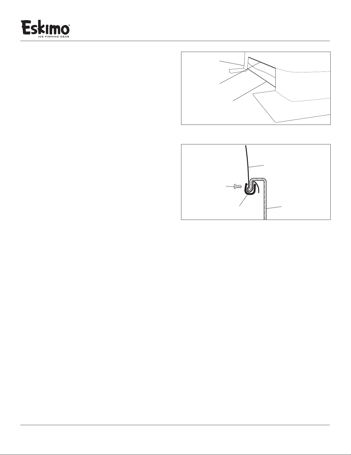
trim piece (69306) from the parts box. Locate the center of
the edge trim piece by folding it in half. Line up the center
of the edge trim to the best of your ability with the center of
the rear of the shelter. SEE FIGURE 17 (see next page)
pole clamp
¼-20 nylock nut
FIGURE 13
door spreader
pole assembly
¼-20 nylock nut
pole clamp
FIGURE 14
pole retention clip
¼-20 x 3/4” bolt
door spreader
pole assembly
¼-20 x 3/4” bolt
#10-24 nylock nut
25. Pull the skin taught and push the edge trim over the lip of the
sled with the shelter skin between the two. It is important to
keep the skin taught and work the edge trim evenly around
both sides of the shelter until all edge trim is in place. SEE
FIGURE 18 (see next page)
Note: When pulling the shelter skin tight, DO NOT lift the
#10-24 X ½” bolt
lower frame support o the ground. Make sure all spreader
poles were properly installed before the edge trim was
FIGURE 15
attached to ensure a proper t. Using a rubber mallet may
be helpful while attaching the edge trim to the sled lip.
26. Secure the edge trim in place using the #6 x 3/8” sheet metal
pole retention clip
screws provided. A cordless drill and Phillips head bit is
recommended for this step, but is not necessary. SEE FIGURE
18 (see next page)
Note: Screws should be spaced evenly apart. This step does
mean you will put very small holes in your shelter skin to
keep the edge trim and skin securely attached to the sled lip.
This will in no way aect the performance of your shelter.
FIGURE 16
Check for parts online at www.GetEskimo.com or call 800-345-6007 M-F 8-5 CDT
spreader pole
7
Page 8
ADDITIONAL INSTALLATION
14. Locate the included 8 foot tow rope that was in the hardware
bag. To install the tow rope locate the two holes in the front
of the sled and push each end of the rope through a hole. Tie
a knot at each end of the rope to keep the rope from pulling
through the holes. This tow rope is designed for manual
pulling by hand only. DO NOT tow behind a motorized vehicle
with rope. For high-speed towing, you should purchase the
Eskimo Universal Tow Hitch accessory (11608).
Operator's Manual
ESKIMO® FlipMo™ 2 Inferno
skirt
edge trim
sled
GEAR NET
Included with you Eskimo FlipMo™2 Inferno is a gear net to keep you
organized on and o the ice.
15.To install the gear net (15596) to the sled attach the hook and
loop retainers to the rear seat rail (14818). After attaching the
gear net to the seat rails, locate the 24 inch piece of edge
trim along with the remaining edge trim screws used earlier.
Secure the gear net by attaching it to the front of the sled lip
with the edge trim and edge trim screws.
SETUP AND TAKEDOWN INSTRUCTIONS
Set-Up: From the outside or inside of the shelter depending
on your preference, start with the lower frame support and
fully extend until it snaps into place. As you extend each frame
support to the “in use” position make sure they snap into place.
Lastly secure all frame supports by attaching the appropriate
spreader poles as directed earlier in this manual.
Note: By detaching the back spreader pole and the front side
spreaders, you can ip the shelter back halfway into a “windbreak” position on nice days.
Take-Down: Close all window covers, vents covers and zip the
door shut. Remove all spreader poles and snap each spreader
pole onto its respective pole retention clip. This is the “stow
and go” position of your spreader poles. Starting with the rear
frame support, collapse each frame support working toward
the front of the shelter and lower frame support. Flip all frame
poles back. Use caution when ipping poles back to make sure
no parts of the skin get pinched or torn. Fold excess skin inside
of sled when complete.
Note: Use extreme caution so you don’t rip or tear any portion
of the skin, especially around the hinges or any pinch point
areas.
FIGURE 17
skin
#6 - 3/8” screw
edge trim
FIGURE 18
sled
LONG-TERM STORAGE
• Alwaysmakesureyouriceshelteriscompletelydrybefore
storing for long periods of time. Storing your ice shelter
when damp or wet may cause mold and mildew damage.
• Removeskinfromicesheltersledandpoles.
• Clean allsalt,moisture and debris from your shelter skin,
sled and poes. Wipe down poles with a wet rag.
Note: Lubricate the slide poles with a silicon spray at
least seasonally. Do not use oil or grease as a lubricant.
Note: Before attaching skin for use, spray silicon spray
inside of poles for ease of sliding.
• Store skin, poles and sled ina cool,dry placeawayfrom
rodents.
Note: An Eskimo Travel Cover (69172) may be purchased to
protect your shelter while transporting to and from the lake.
8
Check for parts online at www.GetEskimo.com or call 800-345-6007 M-F 8-5 CDT
Page 9
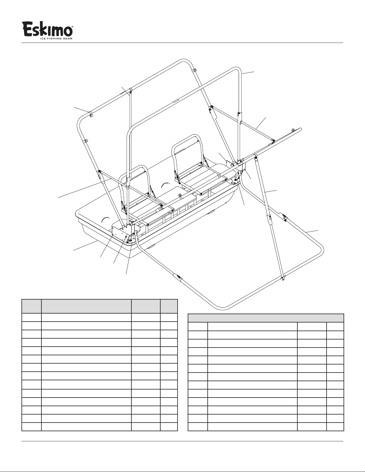
PARTS EXPLOSIONS
Operator's Manual
ESKIMO® FlipMo™ 2 Inferno
FlipMo™ 2 Inferno
5
10
9
14
13
4
7
12
8
11
1
3
6
2
FLIPMO™ 2 INFERNO PARTS LIST
REF.
NO. DESCRIPTION PART NO. QT Y.
SLED
1
PLATE CORNER MOUNT FLIPMO 3
2
RISER HINGE A
3
RISER HINGE B
4
ASSEMBLY POLE SPREADER 19.125”
5
ASSEMBLY HINGE 3 MAN A
6
ASSEMBLY HINGE 3 MAN B
7
BRACE SUPPORT HINGE
8
ASSEMBLY POLE REAR SPREADER 49.5“
9
ASSEMBLY TOP CROSS BRACE W PLASTIC 72.45”
10
ASSEMBLY BOT CROSS BRACE W/PLASTIC E300
11
ASSEMBLY POLE FRONT SPREADER 61”
12
ASSEMBLY POLE SPREADER 22.5”
13
CLIP POLE RETAINER
14
69390 1
11599 2
68052 1
68053 1
15706 2
68141 1
68142 1
11203 2
15703 1
68131 3
68129 1
15702 1
15700 2
15708 12
ITEMS BELOW NOT SHOWN
WASHER 1/4” FLAT ZINC
NUT 1/420 HNYLK ZN
BOLT 1/420 X 2 1/4” HHCS GR5 ZN
BOLT 1/420 X 1 1/4” HHCS GR5 ZN
BOLT 1/420 X 3/4” HH GR5 ZN
BOLT 1/420 X 1” HHCS GR5 ZN
BOLT 1024 X 1/2 PPHMS GR5 ZN FT
NUT 1024 HNYLK ZN
BOLT 1/420 X 11/2 HHCS GR5 ZN
ROPE 1/4” X 8’ TWISTED BLK
SCREW 6 X 3/8” PTHA ZN
EDGE TRIM 1/4” CUT TO 114 INCH
GEAR NET
48261 88
67538 40
48271 8
8909 8
8930 6
69345 6
4827 6
53606 6
48240 6
8930 1
69629 13
69306 1
15596 1
Check for parts online at www.GetEskimo.com or call 800-345-6007 M-F 8-5 CDT
9
Page 10
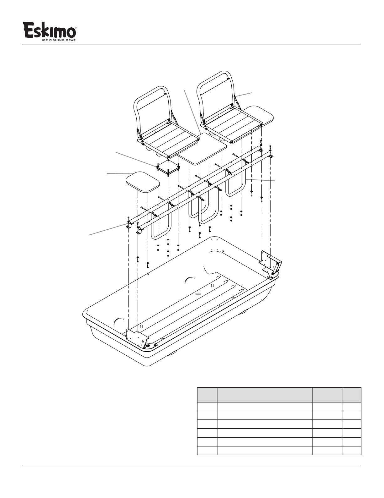
PARTS EXPLOSIONS
FlipMo™ 2 Inferno
Operator's Manual
ESKIMO® FlipMo™ 2 Inferno
4
5
3
1
6
2
10
FLIPMO™ 2 INFERNO PARTS LIST
REF.
NO. DESCRIPTION PART NO. QT Y.
SEAT RAIL
1
FRAME VERTICAL SUPPORT
2
ASSEMBLY TABLE 12.125” X 9.125”
3
ASSEMBLY TABLE 17.375” X 12.5”
4
SWIVEL VERSA MOUNT
5
SEAT VERSA TOP
6
Check for parts online at www.GetEskimo.com or call 800-345-6007 M-F 8-5 CDT
14818 2
11305 4
11331 2
15646 1
15016 2
15004 2
Page 11

Operator's Manual
ESKIMO® FlipMo™ 2 Inferno
FLIPMO™ 2 INFERNO
Warranty Terms and Conditions
PRODUCT WARRANTY: 1YEAR LIMITED WARRANTY
Ardisam, Inc., warrants this Eskimo® FlipMo™ 2 Inferno under a one-year limited warranty to be free from defects in materials or
workmanship or both for a period not exceeding twelve consecutive months from the date of original purchase by the rst retail
consumer or commercial end user. “Consumer use” means personal recreational use by a retail consumer. “Commercial use” or
“commercial application” means all other uses, including use for commercial, income producing or rental purposes. Once a product
has experienced commercial use, it shall thereafter be considered as a commercial use product for purposes of this warranty.
This warranty does not cover cracked windows, tent tears, or bent poles due to use in high wind, inclement weather conditions,
unattended use or uses other than those listed in the owner’s manual. This warranty applies to the original owner that provides a
proof of purchase of the shelter. The warranty is not transferable. The warranty period begins on the date of purchase by the rst retail
consumer or commercial end user, and continues for the twelve month consecutive period thereafter. Any unit used in a commercial
application is covered for a period of 90 days after purchase. For the warranty to be valid, the product must be registered online at
www.GetEskimo.com, or the warranty card must be lled out and received by Ardisam, Inc., within 30 days of purchase. Ardisam, Inc.
shall not be obligated to ship any repair or replacement product to any location outside of the United States of America or Canada.
For replacement parts, phone 800-345-6007 or go online to www.geteskimo.com.
*This warranty applies only to products which have not been subjected to negligent use, misuse, uses other than those indicated in the
product’s owner’s manual, alteration, accident, use of unauthorized parts, failure to perform periodic maintenance as specied in product’s
owner’s manual, normal wear and tear, use of unauthorized parts or repairs performed at non-authorized service centers. There is no other
expressed warranty. Implied warranties, including those of merchantability and tness for a particular purpose, are limited to one year from
purchase, or to the extent permitted by law. All other implied warranties are excluded. Liability for incidental or consequential damages are
excluded to the extent exclusion is permitted by law. Ardisam, Inc. does not assume, and does not authorize any other person to assume
for us, any liability in connection with the sale of our products. To obtain warranty service, you must have prior approval by calling our
customer service department at 1-800-345-6007. If you choose to ship your product to Ardisam for warranty repair, you must rst have
prior approval from Ardisam by calling our customer service department for a return material authorization number (RMA#). Under these
circumstances, all items must be shipped prepaid. Ardisam will at no charge, repair or replace, at their discretion, any defective part which
satises all conditions stated above. Ardisam retains the right to change models, specications and price without notice. Ardisam, Inc. shall
not be obligated to ship any repair or replacement product to any location outside of the United States of America or Canada.
ESKIMO®
A Division of Ardisam, Inc.
1160 Eighth Avenue; P.O. Box 666
Cumberland, Wisconsin 54829
1-800-345-6007 · Fax (715) 822-4180
E-mail: [email protected]
Check for parts online at www.GetEskimo.com or call 800-345-6007 M-F 8-5 CDT
11
Page 12
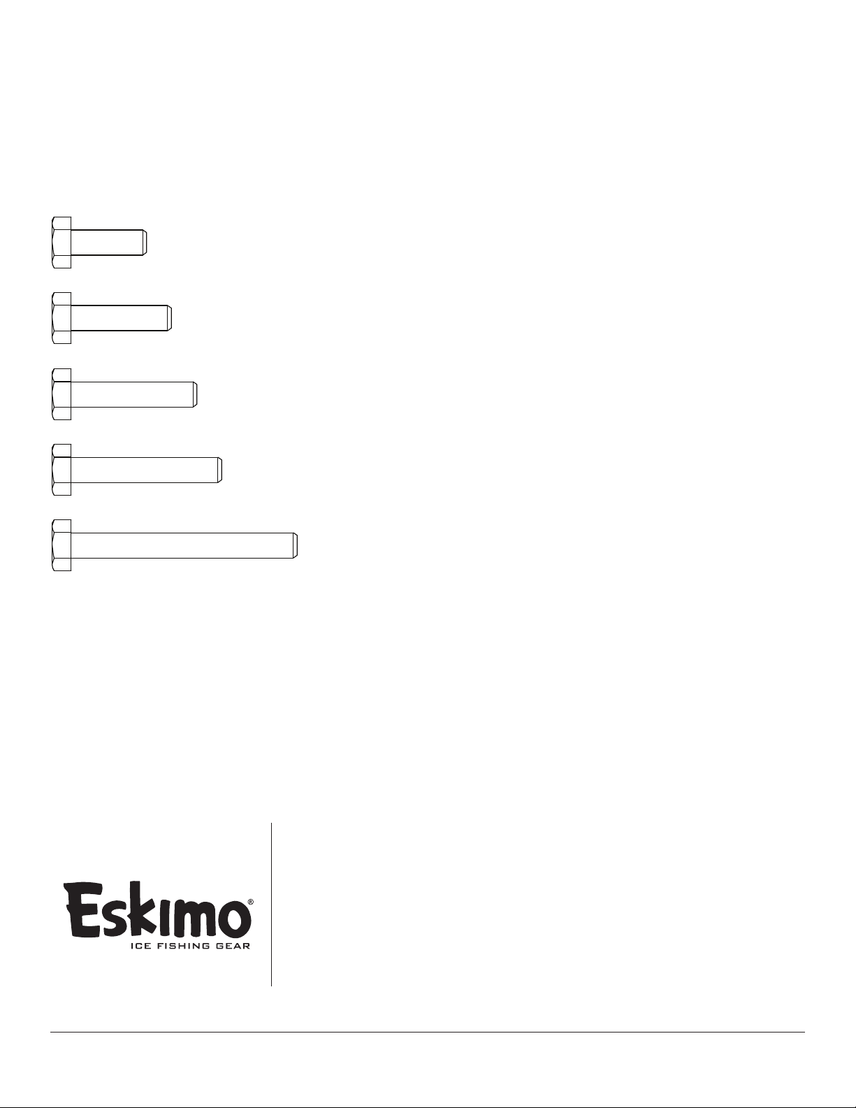
BOLT IDENTIFICATION CHART
• Not all bolt sizes shown are included with all shelters. Bolts
shown are for size reference only. Extra hardware may be
included in the parts bag.
BOLT 1/420 X 3/4” HH GR5 ZN
BOLT 1/420 X 1” HH GR5 ZN
BOLT 1/420 X 11/4” HH GR5 ZN
BOLT 1/420 X 11/2” HH GR5 ZN
BOLT 1/420 X 21/4” HH GR5 ZN
Eskimo®, Division of Ardisam, Inc.
1160 8th Avenue, PO Box 666
Cumberland, WI 54829
800-345-6007 | Fax 715-822-2223
Email: [email protected]
All weights, specifications and features are approximate and are
subject to change without notice. Due to continuous product
improvements, product images may not be exact. Items used for
props not included. Some assembly may be required.
Check for parts online at www.GetEskimo.com or call 800-345-6007 M-F 8-5 CDT
 Loading...