

ES-Key 1Touch 1200-04-00-CL1, 1Touch 1200-12-00-CL1, 1Touch 1200-08-00-CL1, 1Touch 1200-16-00-CL1 Quick Manual
Page 1
WIRING
1Touch
®
switch - Quick Manual
1Touch® switch Quick Manual P/N 121693
ENABLING PASSWORDS
REV A
5-19-2011
The 1Touch has one 6-pin Deutsch connector.
Mating connector: Deutsch DT06-6S
Mating sockets: Deutsch 0462-201-16141
Gold mating sockets: Deutsch 0462-201-1631 (* for CAN connections)
Recommended wire gage: 16-20 AWG
Wedge lock: W6S
PIN CIRCUIT DESCRIPTION
1 SYS POWER (INPUT) – battery voltage (+9VDC…+32VDC)
2 SYS GROUND (INPUT) – battery ground
3 DIM INPUT
4 CAN HIGH (DATA) – SAE J1939 CAN 2.0B, 250Kbits/s *
5 CAN LOW (DATA) – SAE J1939 CAN 2.0B, 250Kbits/s *
6 CAN SHIELD (DATA) – SAE J1939 CAN 2.0B, 250Kbits/s *
(INPUT) – Configurable, analog or digital
(ground to battery voltage)
SWITCH CAP INSTALLATION
The 1Touch switch caps and labels are easily installed with no
special tools required.
The switch labels must be custom created. Consult the full manual
for detailed information about the label.
1. Adhere the switch label
to the rubber switch pad.
Take special care to
place the label with
proper orientation.
If more than 60 seconds has elapsed since the 1Touch switch was
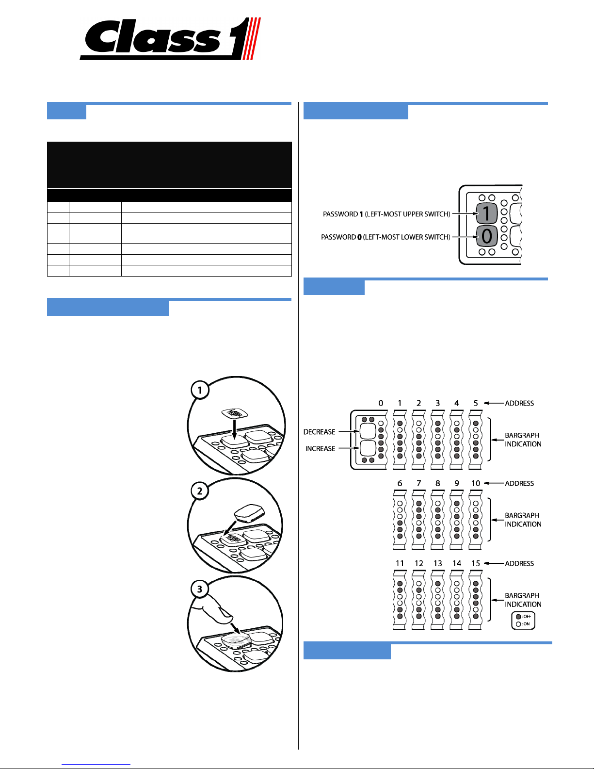
powered you must enter the ENABLE password: 1101 1011.
The panel’s switch backlighting will blink once to indicate the
password has been accepted. Standard password entry is now
enabled for the next 60 seconds.
ADDRESSING
The 1Touch switch’s address may be set by entering the following
password: 1001 0010.
Switches 0 and 1 are now lit and all other switches are OFF. The
red LED bar graph indicates the current address (see graphic
below).
Press switch 1 to decrease the address value. Press switch 0 to
increase the address value.
Press any other switch to save the address and resume normal
operation.
2. Place one corner of the
switch cap into the corner
of the switch opening.
3. Press the switch cap’s other
corner firmly into place using
finger pressure.
LOADING DEFAULTS
To load the 1Touch’s defaults, enter the password: 1001 1001.
This sets all of the switch types to bi-stable, address to 0, device
type set to 5, initial power states to OFF, LED indicator controlled
internally, and network mode set to ES-Key.
Page 2
DEVICE TYPE CONFIGURATION
SWITCH TYPES
The 1Touch switch is normally a device type 5 (SPS) but may be
configured as a device type 4 (Input Output Module).
Device type 4 password: 0111 0100
Device type 5 password: 0111 0101
INITIAL POWER ON STATES CONFIGURATION
The 1Touch switch’s Initial Power ON States may be set by entering
a password: 1001 0000.
All of the switch backlighting and indicator LEDs begin flashing.
Each switch’s associated green indicator LED shows the configured
initial power ON state.
Press the switches to toggle the desired initial power ON state.
When the “initial power ON states” is set as desired let the panel
time out (15 seconds) – the bar graph (red LEDs) shows the
countdown. The panel will save the configuration and resume
normal operation.
LED INDICATOR CONTROL SOURCE
The 1Touch switch can be configured for Internal or ES-Key control
of the switch’s LED indicators (green and yellow LEDs).
Internal control (default)
The state of the switch controls the associated green LED indicator.
ES-Key control
The 1Touch switch panel’s output memory space controls the state
of the green and yellow LED indicators.
To configure the switch panel’s LED indicator control method, enter
the password: 1001 0011.
Switch 0’s back lighting is ON and all other backlighting is OFF. The
indicators LEDs show the state of indicator control.
Green LEDs ON = Internal control method.
Green AND
Press switch 0 to toggle between the indicator control methods.
Press any other switch to save and resume normal operation.
MASTER SWITCH CONFIGURATION
yellow LEDS ON = ES-Key control method.
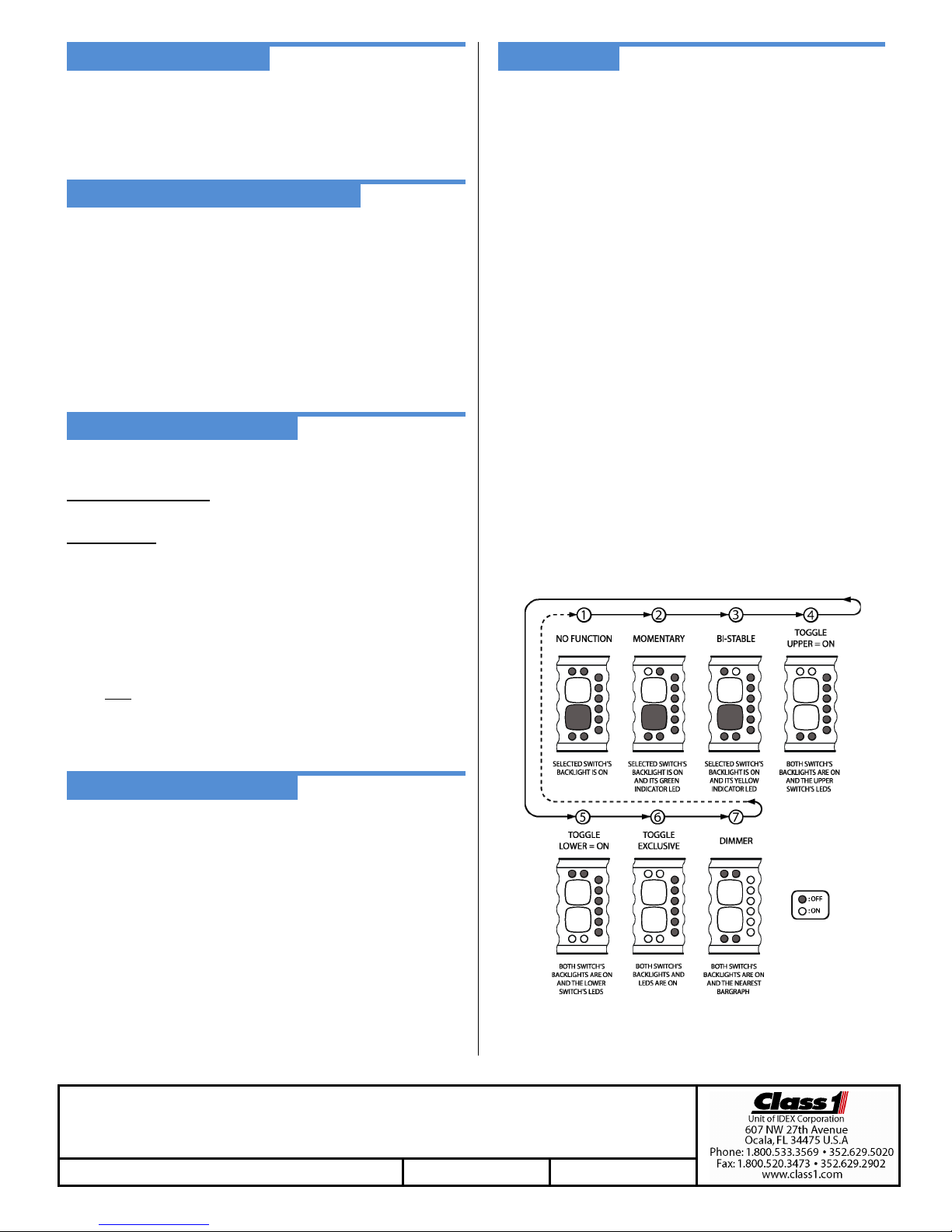
The 1Touch switches can be set to one of seven different types: no
function, momentary, bi-stable, toggle (top = ON), toggle (bottom =
ON), toggle (exclusive), and dimmer.
Three of the switch types (no function, momentary, and bi-stable) are
individual switch types. The remaining four switch types are paired
switch types.
Enter the password for the switch bank to configure.
Switch bank 0: 1000 0000
Switch bank 1: 1000 0001
Switch bank 2: 1000 0010
Switch bank 3: 1000 0011
Switch bank 4: 1000 0100
Switch bank 5: 1000 0101
Switch bank 6: 1000 0110
Switch bank 7: 1000 0111
The switch bank’s back lighting is now lit and all other lighting is OFF.
Press the switch (top or bottom) of the switch bank to configure. The
switch bank’s backlighting and indicator LEDs (green and yellow)
show the selected switch’s current switch type.
Press the selected switch again to increment to the next switch type.
The other switch in the switch bank may be pressed to change its
switch type also.
The graphic below shows the upper switch lit for the individual switch
types. The switch which has been selected will be lit when showing
the individual switch types – for example, if the bottom button is being
pressed then the bottom button’s backlighting will be lit and viceversa.
The 1Touch switch can utilize one master switch. The state of the
master switch controls the functionality of all the other switches.
When the master switch is OFF all other switches will be OFF and
not illuminated.
To configure a master switch enter the password: 1001 0001.
All backlighting is now flashing and the bargraph LEDs are counting
down.
Allow the bargraph LEDs to fully countdown (15 seconds) without
pressing a button to remove any master switch.
Press any switch to configure the associated switch bank as a
master switch. A master switch may be configured as a toggle
(top = ON) or toggle (bottom = ON) switch type.
Press any other switch to save the master switch configuration and
resume normal operation.
For detailed operation and troubleshooting consult the full manual (p/n 121677).
© Class1 2011 all rights reserved
1Touch® switch Quick Manual REV A 5-19-2011
Press any other switch to save the current switch bank configuration
and resume normal operation.
 Loading...