

Page 1
1
User Guide ORBIS 9 Cellular and WLAN Jammer
CONTENTS
• 01/ CASE CONTENTS
• 02/ GETTING STARTED WITH THE ORBIS 9
• 03/ WHEN TO USE THE ORBIS 9
• 04/ SETTING UP THE ORBIS 9 FOR JAMMING
• 05/ OPERATING GUIDE
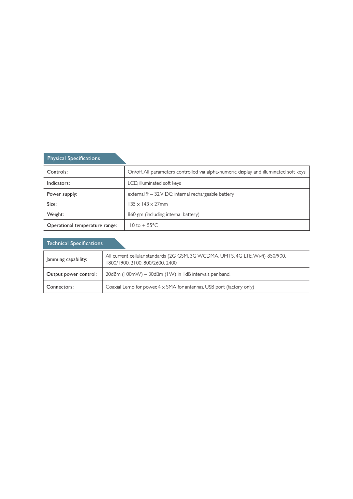
• 06/ SPECIFICATIONS
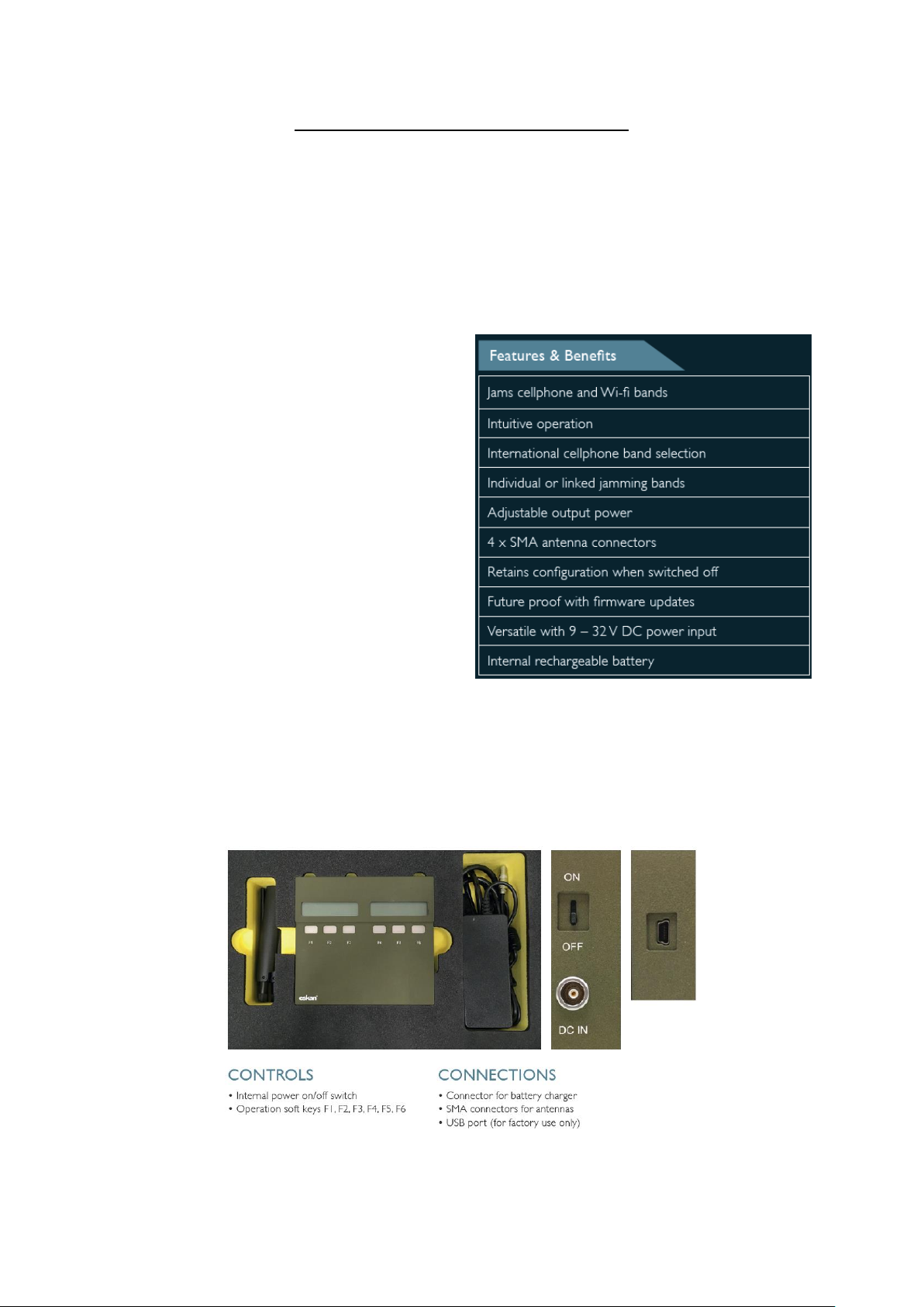
The ORBIS 9 prevents leakage of sensitive
information and data through cell phones, disables
satellite tracking device reporting systems, and
prevents cellphone activation of remotely
controlled equipment. This portable, configurable,
cellular and wireless LAN (Wi-Fi) jammer jams
nearby portable phones and other devices which
use cellular and Wi-Fi frequencies. It jams six bands
which can be either independently controlled or
linked together for simultaneous operation.
Developed primarily for law enforcement and
military agencies, the ORBIS 9 jams cell phones
whether in active or stand-by mode. By disrupting
the network signals, the ORBIS 9 prevents the
cellphones from establishing a call and receiving
/sending text messages or data. It can be
programmed for accurate jamming by selecting the country of use and the output power level.
01/ CASE CONTENTS
• Unit: ORBIS 9
• Accessories: 4 x antenna, Power supply and lead
• Carrying case: Purpose built with internal foam cut-out
Page 2

2
02/ GETTING STARTED WITH THE ORBIS 9
2.1 / POWER SUPPLY
2.1.1 Internal battery pack
The unit includes a high-capacity Lithium Ion battery pack and built-in intelligent battery charger.
2.2 / USING THE MAINS POWER SUPPLY
A 100-240VAC mains power supply with a 15V 40W output is provided.
Note 1: The internal charger accepts a wide range of voltages between 9V and 32V (negative ground).
Note 2: The ORBIS 9 is protected against the transients expected from 12V and 24V vehicle power
supplies, and against reversed voltage.
Note 3: A 40W external power source allows the unit to operate and recharge simultaneously, and
will recharge the battery in approximately 2 - 3 hours when the unit is switched off. Charge times may
be longer if the unit is in use at the same time.
Note 4: The battery is protected against overcharge and over-discharge; no special precautions are
needed. Battery life depends on the bands enabled and transmitter power, and is approximately
45mins for continuous transmission on all bands at maximum power.
2.2.1 When the battery is almost exhausted a “Battery Low” warning will intermittently flash on the
screen.
2.2.2 Connect an external power source to continue operating without interruption.
2.2.3 When the battery is exhausted a continuous “Recharge Battery, switch off first” message will
appear.
2.2.4 Switch off the unit and connect the charger. Once the charger is connected the unit may be
switched on and used while the battery is charging, however this will increase the battery charge time
from the normal 2 to 3 hours.
Note: When the charger is connected a glow can be seen in the F6 key, indicating the approximate
state of charge:
Green: Fully charged Orange: Partly charged Red: Low charge level
2.3 / SWITCHING ON
Important: before switching on connect antennas to all four coaxial (SMA) connectors. The standard
unit is supplied with four multi-band antennas. Depending on the region and application, different
antennas may be supplied for specific bands, in which case the antenna labels must match the labels
on the case. If alternative antennas are used for specialist applications ask suppler for advice.
2.3.1 With all four antennas connected, slide the power switch on the side of the unit to “ON”.
Note: The product name, firmware versions, serial numbers and geographic region are shown
sequentially in the alphanumeric display.
2.3.2 Check that the geographic region is correct, and if it is not select the correct region in the Country
Configuration menu (see configuration section)
Page 3
3
2.3.3 To skip this “sign-on” information to be ready for immediate operation press the F3 and F6 keys
before switching on, and release the keys immediately after switching on.
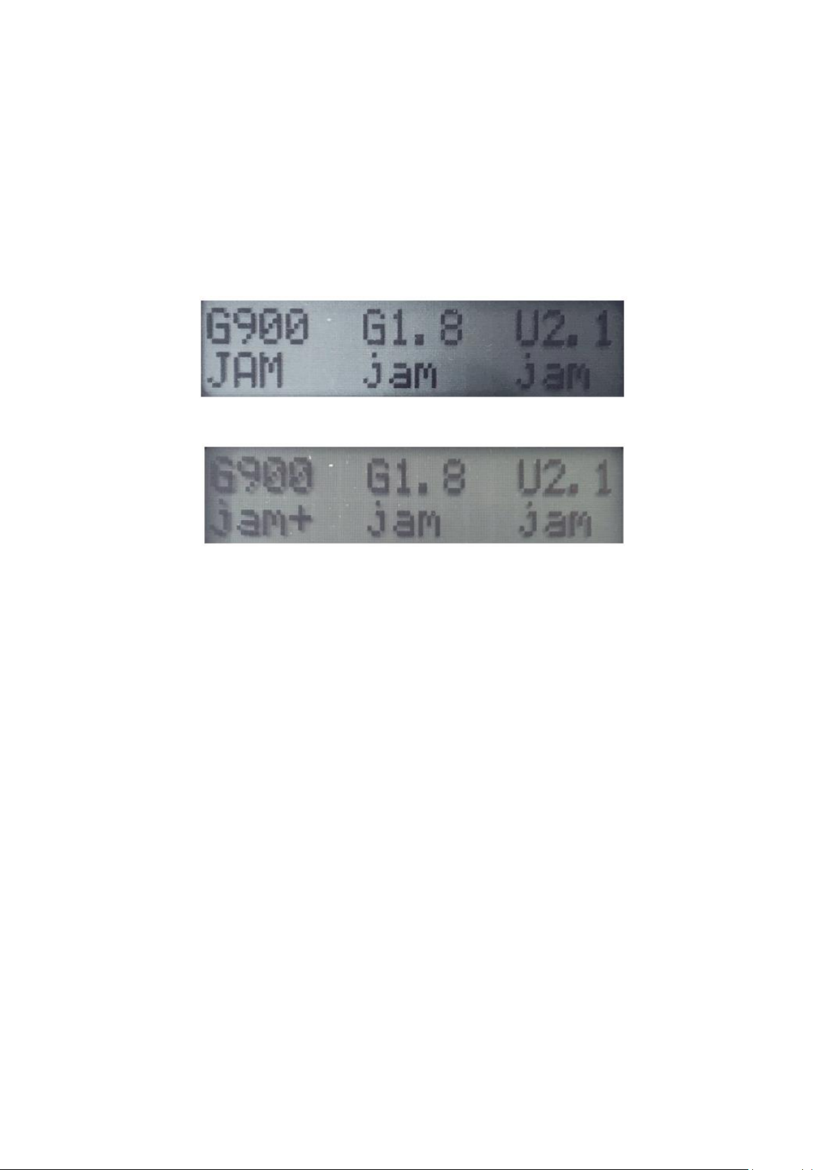
Note: When the ORBIS 9 is ready for use, the six keys F1 to F6 are labelled with the corresponding
bands, and the current jamming status. The top line of the display indicates the band, which depends
on the selected country / region, and the bottom line shows the current status of that band. The status
of this band can be:
• ---- Disabled either through country selection or band configuration menu.
• jam “jam” in lower-case means jamming is available but not currently active.
• JAM “JAM” in upper-case means the unit is currently jamming on this band.
• “JAM” and “jam” will be followed by a “+” if the band is linked. All linked bands switch
between jamming and inactive states simultaneously. See below for a detailed explanation of
linked bands.
Bands currently jamming are also indicated by red illumination of the corresponding key, unless the
key illumination has been disabled via the configuration menu.
03/ WHEN TO USE THE ORBIS 9
The portable ORBIS 9 is a cellular and wireless LAN (Wi-Fi) jammer which jams nearby portable phones
and other devices which use cellular and Wi-Fi frequencies. It jams six bands which can be either
independently controlled or linked together for simultaneous operation. These bands include:
3.1.1 Legacy 2G (originally GSM only) bands (900MHz / 1800MHz in EU / Middle East). In many regions
these bands now contain UMTS/WCDMA and 4G (LTE) signals as well as GSM.
3.1.2 3G UMTS/CDMA band (2100 MHz in EU / middle East).
3.1.3 800MHz 4G (LTE) band
3.1.4 2.6GHz 4G (LTE) band.
3.1.5 2.4GHz Wireless LAN (Wi-Fi) band.
04/ SETTING UP THE ORBIS 9 FOR JAMMING
4.1 / CONFIGURATION
There are two types of configuration: global configuration and individual band configuration.
Page 4
4
4.2 / GLOBAL CONFIGURATION
Configuration options affecting all three bands are selected via the global configuration menus.
4.2.1 To configure the unit press the F1, F2 and F3 keys, or the F4, F5 and F6 keys simultaneously to
enter the Configuration Menu for the left-hand or right-hand side of the unit. The top line of the
relevant display shows Cfg: followed by the item to be configured.
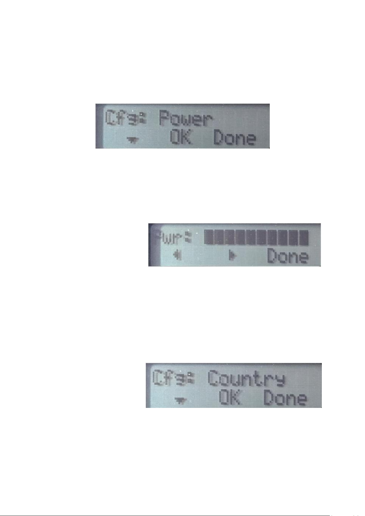
4.2.2 Repeatedly press the F1 or F4 keys (with down arrow) in these menus to cycle through the list
of configurable items until the required item is visible in the top line. Example: Cfg: Power allows the
output power to be adjusted.
4.2.3 To configure a displayed item press OK (F2 or F5) to enter the configuration menu for that item.
The configuration details depend on the item being configured. The main items to be configured are:
4.2.4 Press F1/F4 keys to show Power Configuration.
The power is adjustable from
20dBm to 30dBm for left and right
sides (F1-F3, F4-F6) - 200mW to 2W
total power for all channels
jamming - in 1dB steps shown on
the screen.
Note: Higher power levels improve jamming effectiveness but reduce battery life. If in doubt, use
maximum power to increase the probability of effective jamming.
4.2.4.1 Press F2/F5 to select power adjustment
4.2.4.2 (Note: left and right sides are set independently) To select the power level required, press
F1/F4 to reduce power and F4/F5 to increase power. For maximum power press F1 and F2 together
for 3 seconds (F4 and F5 for right side), and a + sign will display at the end of the bars.
4.2.4.3 Press Done (F3/F6) when finished.
4.2.5 Press F1/F4 keys to show
country Configuration
4.2.5.1 press F1/F4 to scroll up, and
F2/F5 to scroll down country list.
Note: automatic adjustment to
band limits in selected country
4.2.5.2 Press Done (F3/F6) when finished. Note: Each side is independently selectable. If the relevant
region is does not appear in the 4G/WLAN (right-hand) menu select Global.
Important: Modulation characteristics are selected automatically. No further user selection is
required.
Page 5
5
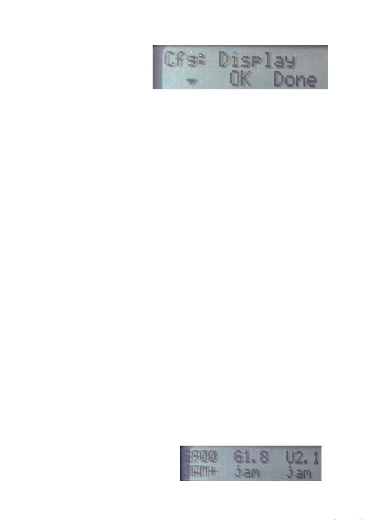
4.2.6 Press F1/F4 keys to show
Display Configuration
This option selects illumination of the
function keys.
4.2.6.1 Select OFF, LOW or FULL on left and right sides
4.2.6.2 Press Done (F3/F6) when finished.
4.2.7 Press done at the Cfg: prompt to leave Global Configuration Mode.
Note: The configuration options are remembered when the unit is switched off or if the internal
battery is fully discharged.
4.3 / BAND CONFIGURATION
The top display row labels each band, In Europe / Middle East the bands are:
• G900: 925...960MHz. Legacy GSM band, also used for UMTS / LTE in some countries
• G1.8: 1.805...1.880GHz. Legacy GSM band, also used for UMTS / LTE (or X1.8 :
1.805...1.920GHz. Extended 1.8GHz band including 1.9MHz TDD allocation)
• U2.1: 2.110...2.170GHz. UMTS (3G) band
• L800: 791...831MHz. LTE (4G) band, previously used for analogue television
• W2.4: 2.4...2.5GHz. Wireless LAN and other unlicensed applications.
• L2.6: 2.62...2.69GHz. International 2600MHz LTE (4G) allocation
4.3.1 Configure each band required by a long press on each band’s function key. (F1 to F6)
4.3.2 Hold the key for the band to be configured for at least one second to enter band configuration
mode for that band only. Note: The relevant key illuminates green to indicate that the band is being
configured.
4.3.3 Cycle through band configuration options with short (less than 0.5s) presses.
Note: The state of the band (Off, On, Link) will be modified and displayed each time the key is released:
Off disables that band completely.
On returning to the main screen the key will be labelled “----” to indicate that jamming is not available.
This function might be used to prevent jamming of a private, secured WLAN network, or to conserve
battery life by disabling a band known to be unused at a particular location.
On allows the band to be independently jammed via its key, regardless of the state of the other bands.
Link adds the band to the list of linked bands (indicated in the Home screen by jam+ or JAM+) which
jam simultaneously when any linked key is pressed.
4.3.4 Exit a band’s configuration mode and return to the Home Screen by a long press on the band’s
key when it displays the desired mode (on, off or link) until the illumination extinguishes.
05/ OPERATING GUIDE
5.1 There are two types of configuration: global
configuration and individual band
configuration. Note: Jamming with linked
bands is always synchronised: they are either
Page 6
6
all active or all inactive. The linked bands will be labelled “jam+” when not jamming and “JAM+” when
jamming.
5.2 Press the function key for one of the linked bands to start jamming on each of the linked bands.
Note: each band’s key will illuminate RED if the display illumination is enabled, and above the key
“JAM+” will be shown in uppercase.
5.3 To stop jamming on all linked bands press any linked band’s key. Note: Any enabled but unlinked
bands are labelled “jam” or “JAM”, without a “+”. These bands can be individually enabled or disabled
with a short press on their key, independently from any other bands. When active, an unlinked band’s
key will illuminate RED if display illumination is enabled, and the label will show uppercase “JAM”
06/ SPECIFICATIONS
 Loading...