

Page 1
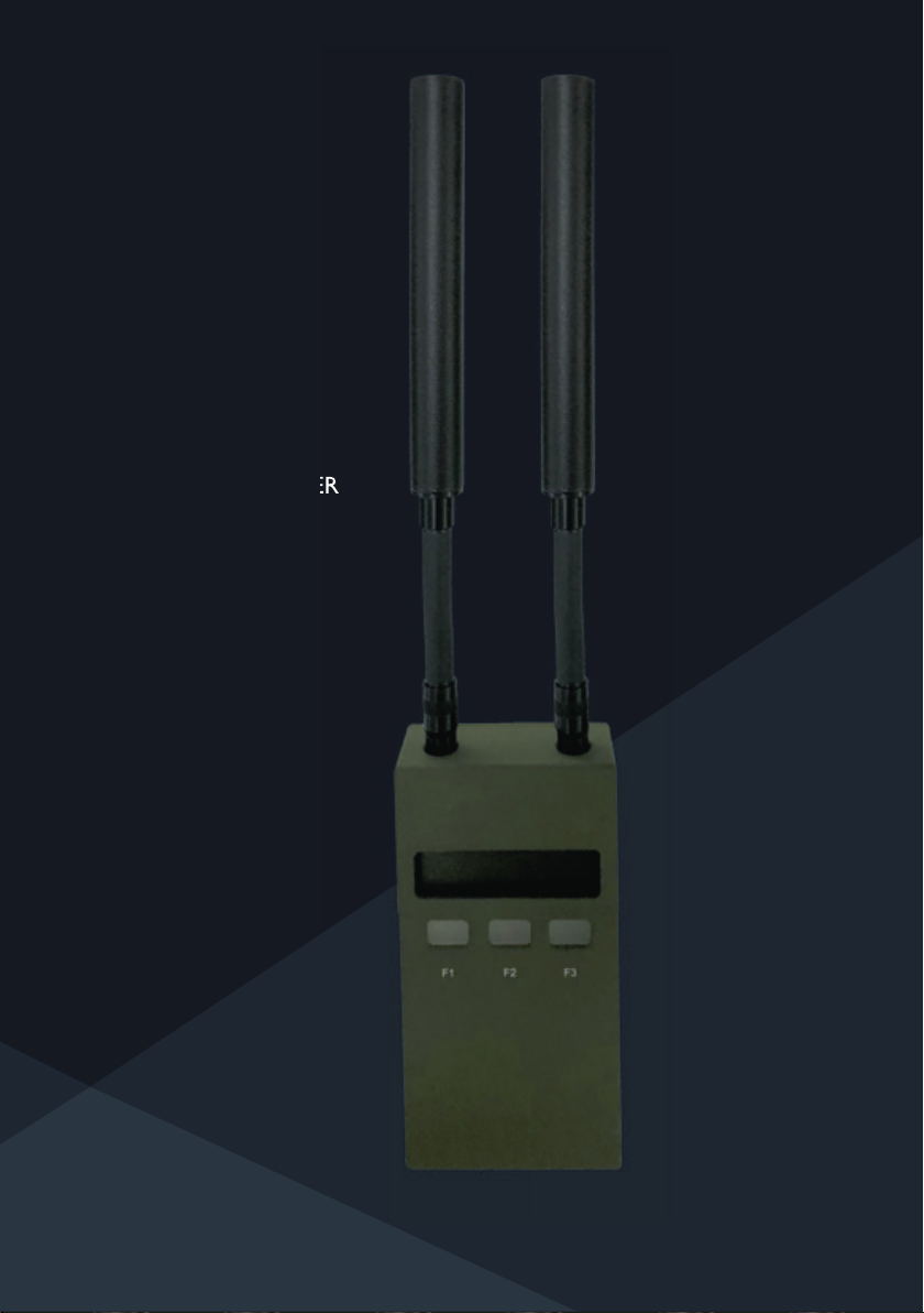
USER GUIDE
ORBIS 5
WLAN SIGNAL JAMMER
Page 2

Changes may be made periodically to the information in this user guide without obligation to notify
any person of such revision or changes. Such changes will be incorporated in new editions of this
user guide or supplementary documents and publications. The manufacturer makes no representa-
tions or warranties, either expressed or implied, with respect to the contents hereof and speci cally
disclaims the implied warranties of merchantability or tness for a particular purpose.
All correspondence concerning this unit should include the code, version number and serial number.
No part of this publication may be reproduced, stored in a retrieval system, or transmitted, in any
form or by any means, electronic, mechanical, photocopy, recording, or otherwise, without the prior
written permission of the manufacturer.
CONTENTS
Case contents, controls and connections 03
Jamming with the ORBIS 5 03
Getting started with the ORBIS 5 04
When to use the ORBIS 5 06
Setting up the ORBIS 5 for jamming 06
Speci cations 11
Preventing the unauthorised use of wireless communica-tion is an essential part of security. The
ORBIS 5 hand held jammer provides protection against un-known use of the 2.4 – 2.5 GHz and 5 -
6 GHz bands using three independent jamming transmitters that can be con gured to ensure that
the wireless signals are jammed only on the frequency bands used in the country selected.
The 5 – 6 GHz band includes sub-bands which can be jammed using the two independent transmitters dedicated to the 5 – 6 GHz band. This capability reduces the jamming power required and
improves the jamming range by con-centrating the jamming power over a narrower band width. In
addition, a global setting option enables band selection outside the country-speci c regulatory band
limits.
The ORBIS 5 is easy to con gure for country spe-ci c or for global frequency bands and for output
power. Where 2 or 3 of the jammer transmitters are required to be active at the same time, they
can be linked using the JAM + feature to enable easier and faster operation.
Features & Benefi ts
Intuitive operation with easily understood display
Disruption of activity on 2.4 - 2.5 and 5 - 6 GHz bands
Selection of region-speci c regulator y band limits
Global setting for wider coverage
Adjustable output power
Retains con guration when switched off
Rechargeable battery
Page 3
01/ CASE CONTENTS, CONTROLS & CONNECTIONS
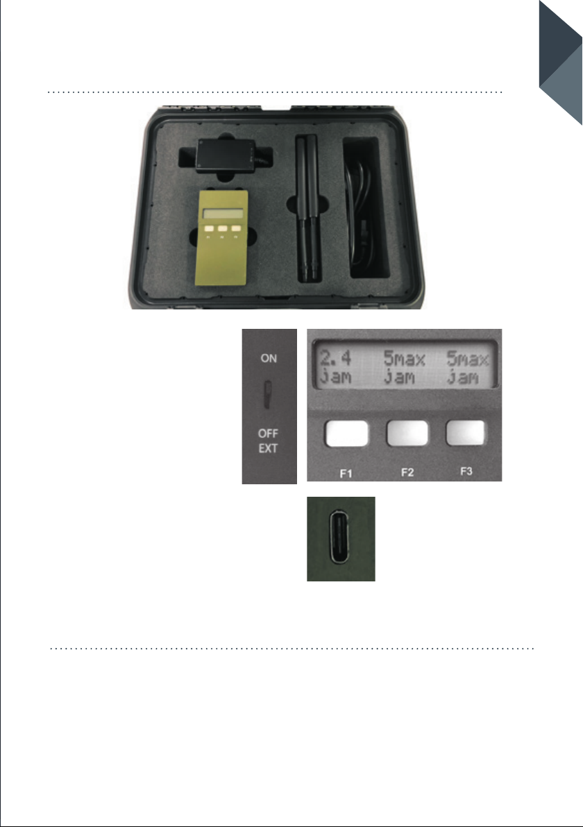
CASE CONTENTS
• ORBIS 5
• 2x Customised antennas
• Mains battery recharger
CONTROLS
03
ORBIS 5 USER GUIDE
• Internal power on/off switch
• Operation soft keys F1, F2
and F3
CONNECTIONS
• Connector for battery charger
• SMA connectors for antennas
02/ JAMMING WITH THE ORBIS 5
The Orbis 5 is designed to disrupt wireless communications in the 2.4...2.5GHz and
5...6GHz bands. Commercial equipment using these bands include wireless LAN,
industrial, medical and radar equipment.
As devices in the 2.4GHz band can mitigate interference by changing frequency, the
ORBIS 5 jams the entire 2.4GHz band continuously with one transmitter.
Page 4

In the 5...6GHz band the ORBIS 5 has two transmitters which can individually be
congured to jam sub-bands or groups of sub-bands for different types of licence free
and licensed communications. The capability to selectively jam sub-bands can reduce
collateral jamming or improve the range by concentrating the radiated power where it
is required.
Each of the transmitters, 2.4GHz and 2 x 5GHz) can be either independently
controlled from the front panel or linked together for simultaneous operation.
Precise band limits are region dependent. A country selection menu allows rapid
conguration for different regions.
03/ GETTING STARTED WITH THE ORBIS 5
The Orbis 5 is designed to disrupt wireless communications in the 2.4...2.5GHz and
5...6GHz bands. Commercial equipment using these bands include wireless LAN,
industrial, medical and radar equipment.
As devices in the 2.4GHz band can mitigate interference by changing frequency, the
ORBIS 5 jams the entire 2.4GHz band continuously with one transmitter.
3.1 / POWER SUPPLY
3.1.1
Internal battery pack
The unit includes a high-capacity Lithium
ion battery pack and built-in intelligent
battery charger.
3.2
Using the mains power supply
The 100- unit is switched off
Note 1: charge times may be longer if
the unit is in use.
Note 2: The battery is protected against
overcharge and over-discharge.
Note 3: Battery life is 2 hours with
continuous transmission on all bands at
maximum power. The actual battery life
depends on the bands enabled and the
transmission power.
3.2.1
When the battery is almost exhausted
a “Battery Low” warning will
intermittently ash on the screen.
3.2.2
Connect an external power source to
continue operating without interruption.
Page 5
3.2.3
When the battery is exhausted a
continuous “Recharge Battery, switch
off rst” message will appear.
3.2.4
Switch off the unit and connect the
charger.
Once the charger is connected the unit
may be switched on and used while the
battery is charging, however this will
increase the battery charge time from
the normal 2 to 3 hours.
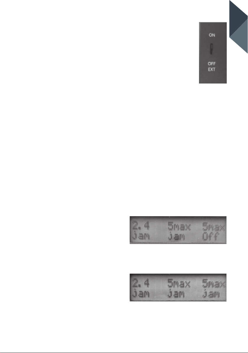
the unit to “ON”.
Note: The product
name, rmware versions
and geographic region
are shown sequentially in
the alphanumeric display.
3.3.2
To skip the “sign-on” information operation press the F3 key before switching
on, and release the key immediately
after switching on.
05
ORBIS 5 USER GUIDE
Note: When the charger is connected
a glow can be seen in the F1 ke y,
indicating the approximate state of
charge:
Green: Fully charged
Orange: Partly charged
Red: Low charge level
Important: due to the 3A current
requirement standard USB chargers
should not be used. Always use the
provided mains charger. Do not use any
voltage other than 5V.
3.3 / SWITCHING ON
Important: before switching on connect
both antennas to the coaxial (SMA)
connectors. If alternative antennas are
used for specialist applications, please
ask the manufacturer for advice.
When the Orbis 5 is ready for use, the
three keys F1 to F3 are labelled with the
corresponding bands (2.4 GHz, 5GHz
sub-band, second 5GHz sub-band) and
the current jamming status.
The top line of the display indicates the
band, and the bottom line shows the
current status of that band. The status of
this band can be:
• Off disabled via the band’s
con guration menution menu
3.3.1
Slide the power switch on the side of
• jam“jam” in lower-case means jamming
is available but not currently active
Page 6
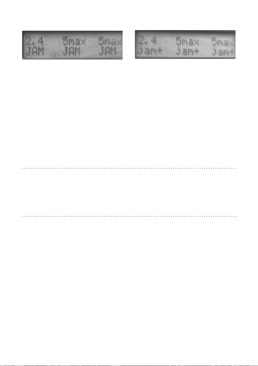
• JAM “JAM” in upper-case means the
unit is currently ja is band.
Bands currently jamming are also indicated by red illumination of the corresponding
key, unless the key illumination has been disabled via the conguration menu.
Note: “JAM” and “jam” will be followed
by a “+” if the band is linked. All linked
bands switch between jamming and
inactive states simultaneously.
(See below for a detailed explanation of
linked bands.)
04/ WHEN TO USE THE ORBIS 5
When there is a requirement to jam wireless communication using 2.4GHz and/or
5GHz frequencies the ORBIS 5 jamming signal will disrupt the communication.
05/ SETTING UP THE ORBIS 5 FOR JAMMING
5.1 / CONFIGURATION
There are two types of conguration
menu: the MAIN MENU and the INDI-
VIDUAL BAND CONFIGURATION
SHORTCUTS. The SORTCUTS menu
bypasses the MAIN MENU to rapidly
enable, disable or link bands.
5.2 / MAIN CONFIGURATION
Conguration options affecting 2.4GHz,
and 2 x 5GHz are selected via the main
conguration menu.
5.2.1
To congure the unit press the F1, F2
and F3 keys simultaneously to enter the
Conguration Menu.
The top line of the relevant display
shows Cfg:
followed by the item to be congured.
Page 7
07
5.2.2
Repeatedly press the F1 key to cycle
through the list
of con gurable items until the required
item is visible
in the top line.
Example: Cfg: Power allows the output
power to be adjusted.
5.2.3
To con gure a displayed item press F2
key (OK) to enter the con guration
menu for that item.
The con guration details depend on the
item being con gured. The main items to
be con gured are:
5.2.4
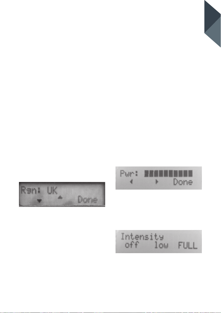
Press F1 key to select Country con gu-
ration
5.2.4.2
Press F3 - Done when nished.
ORBIS 5 USER GUIDE
5.2.5 Press F1 key to show Power
con guration
The power is adjustable between
23dBm and 33dBm (200mW to 2W
assuming all channels are jamming)
in1dB steps, indicated by a bar-graph
to the right of the Pwr: label. Higher
power levels improve jamming
effectiveness but reduce battery life.
If in doubt, use maximum power to
increase the probability of effective
jamming.
5.2.5.1
Select required power level.
Use the F1 and F2 keys to select the
country or region of operation. This will
set the band limits for that region.
5.2.4.1
Select Global to cover the widest band
limits and reduce the risk of illegally
imported equipment intended for other
regions not being effectively jammed.
5.2.5.2
Press F3 - Done when nished.
5.2.6 Display Con guration
This option selects illumination of the
function keys. Select between OFF,
LOW and FULL.
Page 8
5.2.6.1
Select required illumination level
5.2.6.2
Press F3 - Done when nished.
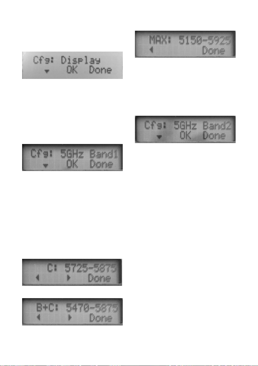
5.2.7 5GHz Sub-band Conguration
The 5GHz band is shared and is divided into sub-bands
Active sub-bands are each indicated on
the display by a one letter abbreviation
for each band. Eg: in the UK if the F2
key is labelled “5BC” then 5GHz bands B
and C are selected. During conguration,
the frequency limits in MHz are shown
for each band the menu entry for band
B plus band C will show B+C: 5470-
5875. (see table of bands for UK).
The available sub-bands may vary with
region, so always congure the Country
before the 5GHz sub-bands.
To cover the whole 5..6GHz band for
the region without any gaps, select MAX
5.2.7.1
Press F1/F2 keys to select the 5GHz
sub-bands for each of the 5GHz channels
5.2.7.2
Press F3 - Done when nished
LEAVING MAIN
CONFIGURATION MODE
5.2.8
To exit conguration mode press Done
at the Cfg: prompt.
Note: The conguration options are
remembered when the unit is switched
off or if the internal battery is fully
discharged.
Page 9
09
5.3 / BAND CONFIGURATION
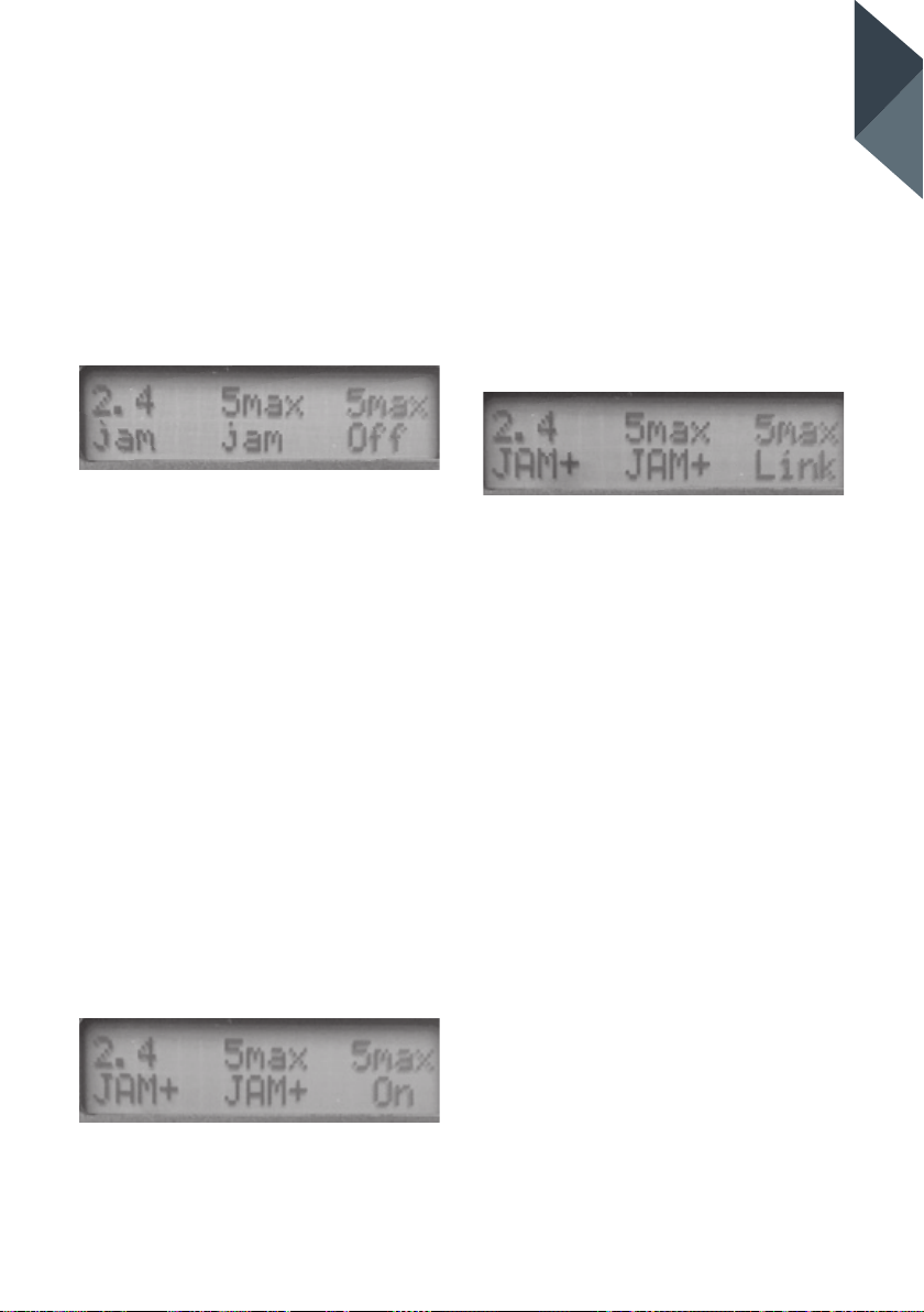
The top display row labels each band:
eg 2.4 5A 5BC
5.3.1
Con gure each band to be AVAILABLE,
DISABLED or LINKED
5.3.2
Hold the key for the band to be
con gured for at least one second to
enter band con guration mode for
that band only.
Note: The relevant key illuminates
green to indicate that the band is
being con gured.
5.3.3
Cycle through band con guration
options with short (less than 0.5s)
presses.
The state of the band (Off, On, Link)
will be modi ed and displayed each
time the key is released:
On indicates that the band is active.
On returning to the main screen the
key will be labelled “----” to indicate
that jamming is not available. This
function might be used to conserve
battery life by disabling a band known
to be unused or required to be left
unjammed.
Link adds the band to the list of linked
bands (indicated in the Home screen
by jam+ or JAM+) which jam simulta-
neously when any linked key is
pressed.
5.3.4
Exit a band’s con guration mode and
return to the Home Screen by a long
press on the corresponding key - until
the green illumination extinguishes.
Con gure each band to be
AVAILABLE, DISABLED or LINKED
ORBIS 5 USER GUIDE
Page 10

5.4 / OVERVIEW OF 5GHZ BANDS
The following table provides an overview of the bands covered by the
ORBIS 5 when UK is selected:
Band
2.4GHz 2.4 2400 2500
5GHz Band A A 5150 5350 Indoor WLAN etc up to 200mW
5GHz Band B B 5470 5725
5.8GHz Band C C 5725 5875
5.9GHz V 5850 5925
Orbis
Display
Lower
limit
(MHz)
Upper
limit
(MHz)
Typical signals
WLAN, Bluetooth, Zigbee,
drones, Toys, shor trange devices.
“Grey import” devices above
2483MHz.
Indoor / outdoor WLAN etc.
1W max.
Licensed xed links, 4W ERP
max. Lowpower shortrange
devices and “grey impor t”
wireless devices.
Shortrange transpor tation
functions including invehicle
systems.
Page 11
06/ SPECIFICATIONS
11
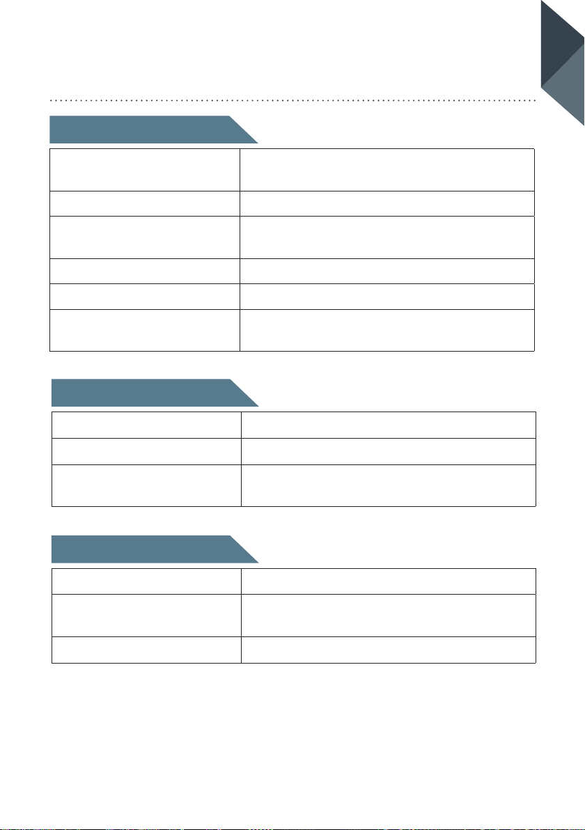
Physical Specifi cations
Controls:
Indicators: LCD
Power supply:
Size: 138 x 72 x 29mm
Weight: 600 gm
Operational temperature
range:
Technical Specifi cations
Jamming capability: 2.4 – 2.5 GHz, 5 – 6 GHz
Output power control: 23 dBm (200mW) – 33 dBm (2W)in 1dB steps
Connectors:
On/off; all parameters controlled via alpha-nu-
meric display and illuminated soft keys
Rechargeable battery (using 5V external power
source via USB connector)
-10 to +65°C
SMA connectors for antennas; USB for power
supply
ORBIS 5 USER GUIDE
Contents
Unit: ORBIS 5
Accessories:
Carrying case: Lightweight purpose built
2 x antennas (SMA connections), 100-240V AC
mains charger supplying 5V 20W output
PALLADIUMC4_UGV1.0_UKA5_1118
Page 12

 Loading...