

ESK OSR-7-54/35, OSR-7-54/4, OSR-7-54, OSR-14-80/54, OSR-14-80/67 Installation And Operating Instructions Manual
...
R744 –
V
H
C
Verfl
r
R744–V
H
[m³/h]
210
240 290
D Montage- und Betriebsanleitung
GB Installation and operating instructions
MADE IN GERMANY
Ölabscheider-Sammler OSR
Die genannten ESK-Komponenten sind Druckbehälter
und ausschließlich für die Anwendung in Kälteanlagen
bestimmt. Sie entsprechen der EG-Druckgeräterichtlinie
2014/68/EU. Eine Inbetrieb nahme ist nur unter der Voraussetzung zulässig, dass der Einbau entsprechend den gesetzlichen Vorschriften erfolgte. Alle Komponenten werden entsprechend den geltenden Regeln konstruiert und
gefertigt. AD-Merkblätter; Druckgeräterichtlinie; EN 378
Anwendung
Alle ESK-Ölabscheider-Sammler
und HFCKW-Kältemitteln und mit Ausnahme vom Typ
auch für den Einsatz mit R 744 (CO2) freigegeben.
Achtung: Für die Ölregulierung verwendete Ölspiegelregulatoren
müssen für hohe Druckdifferenzen geeignet sein.
Tec hnisch e Spezi f i k atio n: Typ OSR-5-.. / OSR-14-.. / OSR-21-..
Max. zulässiger Betriebsüberdruck (P
im Temperaturbereich
[1] Zul. Betriebstemperatur: 140 ... –10 °C P
[2] Zul. Betriebstemperatur: –10 ... – 40°C P
Tec hnisch e Spezi f i k atio n: Typ OSR-7-..
[1] Zul. Betriebstemperatur: 140 ... –10 °C P
[2] Zul. Betriebstemperatur: –10 ... – 40°C PS2: 20 bar
OSR sind für den Einsatz mit HFK W-
OSR-7-54
S max)
S1: 45 bar
S2: 30 bar
S1: 31 bar
Oil Separator Reservoirs OSR
The ESK components mentioned are pressure vessels
and shall be used in refrigeration plants exclusively.
They correspond to EU-Pressure Equipment Directive
2014/68/EU. Operation is only permitted if the installation
was carried out in accordance with legal regulations.
All components are constructed and produced in accordance with the regulations in force. AD leaflets; pressure
equipment guideline; EN 378
Application
All ESK oil separator reservoirs
and HCFC-refrigerants. Except of the type
nents are also suitable for use with R 744 (CO2).
Note please: The selected oil level regulators for the oil management must be suitable for high pressure differences.
Technical specification: Typ e OSR-5-.. / OSR-14-.. / OSR-21-..
Max. allowable operating pressure (P
according to the temperature range
[1] Allow. operating temperature: 140 ... – 10°C P
[2] Allow. operating temperature: –10 ... – 40°C P
Technical specification: Typ e OSR-7-..
[1] Allow. operating temperature: 140 ... – 10°C P
[2] Allow. operating temperature: –10 ... – 40°C PS2: 20 bar
OSR are suitable for use with HFC-
OSR-7-54 the compo-
S max)
S1: 45 bar
S2: 30 bar
S1: 31 bar
Betrieb mit Kältemitteln der Fluidgruppe 1: OSR-FL1
ESK Ölabscheider-Sammler vom Typ OSR können auf Anfrage für
die Kältemittel der Gruppe 1 freigegeben werden und sind mit dem
-FL1 zu bestellen. Die OSR-Geräte für R 290, R 600a, R 717,
Suffix
R 723 und R 1270 werden anstatt mit Rotalock-Ventilen standardmäßig mit Schweiß adaptern ausgeliefert.
Alle geeigneten Kältemittel sind auch auf dem Typschild angegeben. Ausschließlich so gekennzeichnete Geräte dürfen in
Operation with hazardous fluids (fluid group 1): OSR-FL1
ESK oil separator reservoirs types OSR can be approved for all
hazardous fluids on request and are to be ordered with suffix
OSR units for R 290, R 600a, R 717, R 723 and R 1270 applications will
be fitted with welding adapters instead of rotalock valves.
All suitable refrigerants are named on the type plate.
Only in this way designated devices are allowed to operate with
these refrigerants.
-FL1.
Verbindung mit diesen Kältemitteln betrieben werden.
Tec hnisch e Spezi f i k atio n: Typ OSR-FL1
Max. zulässiger Betriebsüberdruck (P
S max)
im Temperaturbereich
[1] Zul. Betriebstemperatur: 140 ... –10 °C PS1: 25 bar
[2] Zul. Betriebstemperatur: –10 ... – 40°C PS2: 10 bar
Technical specification: Typ e OSR-FL1
Max. allowable operating pressure (P
S max)
according to the temperature range
[1] Allow. operating temperature: 140 ... – 10°C PS1: 25 bar
[2] Allow. operating temperature: –10 ... – 40°C PS2: 10 bar
Tec hnisch e Dat en Tec hnical data
Ölabscheider- Inhalt:
Sammler gesamt I Ölabscheider I Ölsammler theo. bei 40°C V
Oil separator Volume:
reservoir total I Oil
Typ V V
Type l l l l l 10 °C 0°C –10°C –20°C –30°C – 30°C – 35°C – 40°C
OSR-5-22 8,9 5,0 3,9 0,9 3,0 35 42 60 73 100 42 50 58
OSR-5-35/28 8,9 5,0 3,9 0,9 3,0 55 64 82 90 120 42 50 58
OSR-5-35 8,9 5,0 3,9 0,9 3,0 70 80 92 105 130 42 50 58
OSR-7-54/35 18,0 10,0 8,0 2,8 5,4 90 102 123 145 175 – – –
OSR-7-54/42 18,0 10,0 8,0 2,8 5,4 90 102 123 145 175 – – –
OSR-7-54 18,0 10,0 8,0 2,8 5,4 90 102 123 145 175 – – –
OSR-14-80/54 32,0 17,7 14,3 5,7 12,5 230 280 345 390 450 135 155 180
OSR-14-80/67 32,0 17,7 14,3 5,7 12,5 280 300 345 390 450 135 155 180
OSR-14-80 32,0 17,7 14,3 5,7 12,5 280 300 345 390 450 135 155 180
OSR-21-104 66,5 46 20,5 8,7 20,0 500 600 700 800 1000 210 240 290
20151102
separator I Oil reservoir ment theo. at 40°C condensing temperature –10°C condensing temperature
OS Vt V1 V2 Verdampfungstemperatur / Evaporating temperature
VH (m³/h) max. zul. Verdichter Hubvolumen, R744 – VH [m³/h], theo. bei:
VH (m³/h) max. allowable compressor displace- R744 – VH [m³/h], theo. at:
erflüssigungstemperatur –10°C Verflüssigungstemperatur
–10°
–10°C condensing temperature
– 30°C – 35°C – 40°C
42 50 58
42 50 58
42 50 58
– – –
– – –
– – –
135 155 180
135 155 180
135 155 180
[m³/h], theo. bei:
üssigungstemperatu
, theo. at:
⇒
www.esk-schultze.de
1/4
Ölabscheider-Sammler
FL1
FL1
OSR
www.esk-schultze.de
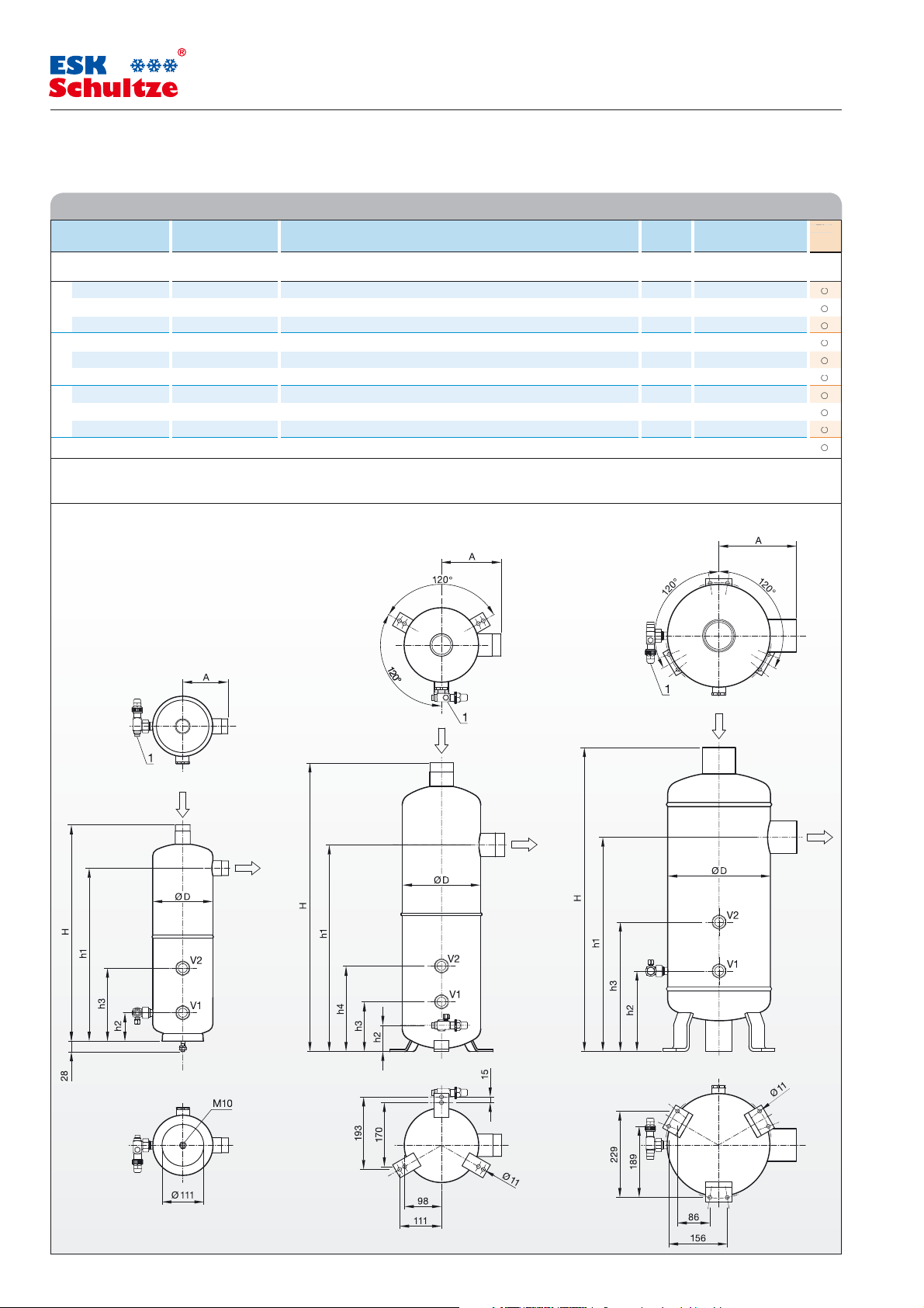
Ölabscheider-Sammler Lötanschluss innen Abmessungen Gewicht DGRL DGRL Typ -FL1 FL1
Oil separator reservoir Solder conn. ODS Dimensions Weight PED PED
Abb. / Typ Ø DL Ø DL Ø D H h 1 h 2 h3 h 4 A Kategorie
Fig. / Type mm inch mm mm mm mm mm mm mm kg Category
a OSR-5-22 22 7/8 162 564 454 76 195 – 122 10,0 II III ○
a OSR-5-35/28
a OSR-5-35
b OSR-7-54/35 35 1-3/8 198 755 521 66 126 216 186 13,5 II III ○
b OSR-7-54/42
b OSR-7-54
c OSR-14-80/54 54 2-1/8 273 849 569 214 344 – 248 45,7 III III ○
c OSR-14-80/67
c OSR-14-80
c OSR-21-104 104 4-1/8 324 1098 827 237 387 – 227 63,0 III IV ○
Ø DL Druckleitungs-Außendurchmesser / Discharge line outside diameter
FL1: ○ Auf Anfrage freigegeben für R 290, R 600a, R 717, R723 und R 1270; das Gerät kann mit der Zusatzkennzeichnung -FL1 bestellt werden
FL1: ○ Available on request for R 290, R 600a, R 717, R723 and R 1270; to order this article the model designation should be completed by -FL1
Abb. / Fig. a Abb. / Fig. b Abb. / Fig. c
28 1-1/8 162 592 453 76 195 – 144 10,0 II III ○
35 1-3/8 162 570 453 76 195 – 122 10,0 II III ○
42 1-5/8 198 755 521 66 126 216 186 13,5 II III ○
54 2-1/8 198 728 521 66 126 216 159 13,5 II III ○
67 2-5/8 273 844 569 214 344 – 243 45,6 III III ○
80 3-1/8 273 808 569 214 344 – 207 40,0 III III ○
Oil separator reservoirs
Dimensions Abmessungen
type -FL1 FL1
2015110220151102
Fußbilder
View feet
1) Ölrückführung, 10 mm Lötanschluss (RAV-1“-10)
Oil return, 3/8“ Solder connection (RAV-1“-10)
⇒ www.esk-schultze.de
2/4
 Loading...