

ESK OS-CD, OS-35-CD, OS-16-CD, OS-35FS-CD, OS-54FS-CD Installation And Operating Instructions Manual
...
D Montage- und Betriebsanleitung
GB Installation and operating instructions
MADE IN GERMANY
Ölabscheider
OS-CD und BOS2-CDM
Die genannten ESK-Komponenten sind Druckbehälter
und ausschließlich für die Anwendung in Kälteanlagen
bestimmt.
Sie entsprechen der EG-Druckgeräterichtlinie 2014/68/EU.
Eine Inbetrieb nahme ist nur unter der Voraussetzung
zulässig, dass der Einbau entsprechend den gesetzlichen Vorschriften erfolgte. Alle Komponenten werden
entsprechend den geltenden Regeln konstruiert und
gefertigt. AD-Merkblätter; Druckgeräterichtlinie; EN 378
Anwendung
ESK-Ölabscheider
mit den Kältemitteln R744 (CO2) und R 410A freigegeben.
Technische Spezifikation
Max. zulässiger Betriebsüberdruck (P
in den Temperaturbereichen:
OS-CD
Typ :
[1] Zul. Betriebstemperatur: 140 ... –10°C ϭ PS1: Siehe Tabelle
[2] Zul. Betriebstemperatur: –10 ... – 40°C ϭ P
Max. Druckdifferenz Ölrückführung: 35 bar
Typ :
BOS2-CDM
[1] Zul. Betriebstemperatur: 140 ... –10°C ϭ PS1 = 60 b ar
[2] Zul. Betriebstemperatur: –10 ... – 40°C ϭ PS2 = 45 bar
Max. Druckdifferenz Ölrückführung: 35 bar
OS-CD und BOS2-CDM sind für den Einsatz
Smax)
S2: Siehe Tabelle
Oil Separators
OS-CD and BOS2-CDM
The ESK components mentioned are pressure vessels
and shall be used in refrigeration plants exclusively.
They correspond to EU-Pressure Equipment Directive
2014/68/EU. Operation is only permitted if the installation
was carried out in accordance with legal regulations.
All components are constructed and produced in accordance with the regulations in force. AD leaflets; pressure
equipment guideline; EN 378
Application
ESK Oil separators
for use with the refrigerants R744 (CO2) and R 410A.
Technical specification
Max. allowable operating pressure (P
according to the temperature ranges:
OS-CD
Typ e:
[1] Allow. operating temperature: 140 ... –10°C ϭ PS1: A s per table
[2] Allow. operating temperature: –10 ... – 40°C ϭ P
Max. differential pressure oil return: 35 bar
Typ e:
BOS2-CDM
[1] Allow. operating temperature: 140 ... –10°C ϭ PS1 = 60 bar
[2] Allow. operating temperature: –10 ... – 40°C ϭ PS2 = 45 bar
Max. differential pressure oil return: 35 bar
OS-CD and BOS2-CDM are suitable
S max)
S2: As per table
Betrieb mit dem Kältemittel R 744 / CO2 (Kohlendioxid)
ESK fertigt Komponenten für den sub- und trans kri tischen
Betrieb. Das Kälte mittel ist farb- und ge ruch los und bei
einem Austritt nicht wahrnehmbar.
Das Einatmen in erhöhter Konzentration kann zu Bewusstlosigkeit
und Ersticken führen. Die Entlüftung der Maschinenräume hat
nach EN 378 zu erfolgen.
Die hohe Drucklage von CO
beachten. Bei Anlagen-Stillstand steigt der Druck bei Um gebungstemperatur erheblich und es kann Berstgefahr bestehen.
Der kritische Punkt liegt bei 31°C und 74 bar.
Absperrbare Anlagenteile sind mit einem Sicherheitsventil auszurüsten (EN 378-2 und EN 13136).
Es darf kein Rohr am Sicherheitsventil angeschlossen wer den, um
beim Öffnen ein Blockieren durch Trocken eis bildung zu vermeiden.
Es können sehr hohe Druckgastemperaturen auf treten, es
besteht Ver bren nungsgefahr an Ölab scheider-Oberflächen
und an Ölrückführ- und Druck aus gleichs leitungen.
ESK-Komponenten dürfen nur für die freigegebenen An wen dungsbereiche eingesetzt werden. Bei Verwendung hochviskoser Kältemaschinenöle > 46 cSt ist die korrekte Funktion der Komponenten
während der Inbetriebnahme zu kontrollieren und zu überwachen.
Gege be nenfalls sind korrigierende Maßnahmen zu ergreifen.
2 stellt eine Gefahr dar und ist zu
Operation with refrigerant R 744 / CO2 (carbon dioxide)
ESK produces components for sub- and transcritical running.
The refrigerant is colorless and odorless, and is not noticeable upon discharge.
Inhaling elevated concentrations can lead to unconsciousness and
suffocation. Ventilation of the machine rooms must be carried out
in accordance to EN 378.
The high pressure condition of CO
be observed. In case of stop of the plant, the pressure elevates significantly at the ambient temperature and there may be
danger of burst. The critical point is 31°C and 74 bar.
Parts of the plant that can be blocked must be prepared with a
safety valve (EN 378-2 and EN 13136.)
To avoid, upon opening, a blocking caused by dry ice accumulation,
it is not allowed to connect a tube to the safety valve.
Very high discharge gas temperatures may develop. There
is a risk of burns at oil separator surfaces and at oil return
and pressure equilazation lines.
ESK components shall only be used within the approved application
range. When using highly viscose cooling machine oils > 46 cSt,
the correct function of the components must be controlled and
monitored during operation. Where applicable, corrective measures must be taken.
2 is dangerous and must
씮 www.esk-schultze.de
1/4
Ölabscheider
16
]
C
Verfl
R744–V
H
OS-CD
www.esk-schultze.de
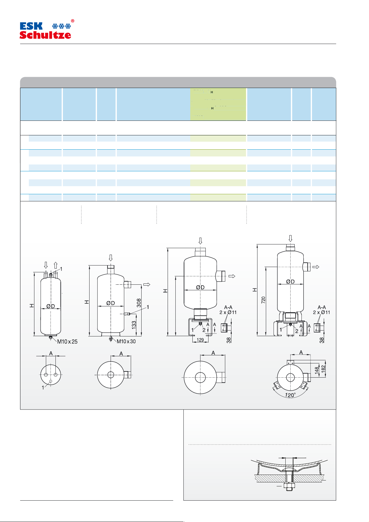
Technische Daten Technical data
Ölabscheider Lötanschluss Inhalt R410A – V
Serie -CD innen Verdichterhubvolumen, theo. bei:
40 °C Verflüssigungstemperatur –10°C Verflüssigungstemp.
Oil separator Solder conn. Volume R410A – V
series -CD ODS compressor displacement, theo. at:
40 °C condensing temperature –10°C condensing temp.
Abb./Typ Ø DL Ø DL Verdampfungstemperatur / Evaporating temperature [°C] Ø D H A
Fig./Type mm inch l 10 0 –10 –20 –30 – 30 – 35 – 40 mm mm mm kg bar bar
a OS-16-CD 16 5/8 2,3 15 16 18 20 26 9 10 11 125 269 60 2,7 53 39
OS-18-CD 18 – 3,7 22 24 27 30 36 14 15 16 125 390 60 3,5 53 39
b OS-22-CD 22 7/8 5,7 35 42 50 60 75 23 25 28 160 418 121 6,1 53 39
OS-35/28-CD 28 1-1/8 5,7 55 60 67 75 90 40 44 48 160 445 143 6,1 53 39
OS-35-CD 35 1-3/8 5,7 80 87 95 110 130 60 65 70 160 423 121 6,0 53 39
c OS-35 FS-CD 35 1-3/8 6,0 80 87 95 110 130 60 65 70 160 624 121 12,9 45 30
OS-54/42FS-CD
OS-54FS-CD 54 2-1/8 21,0 200 250 300 330 370 135 155 180 273 741 202 33,6 45 30
d OS-80FX-CD 80 3-1/8 32,0 325 340 370 400 450 185 215 260 273 955 207 44,7 45 30
42 1-5/8 21,0 120 150 180 200 220 80 95 110 273 768 229 34,0 45 30
Abb. / Fig. a b c d
DGRL: Kategorie I DGRL: Kategorie II DGRL: Kategorie II DGRL: Kategorie III
PED: Category I PED: Category II
[m³/h] max. zulässiges R744 – VH [m³/h] Abmessungen Gewicht PS1 PS2
H
[m³/h] max. allowable R744 – VH [m³/h] Dimensions Weight PS1 PS2
H
PED: Category II PED: Category III
–10°
–10°Ccondensing temp.
ting temperature [°C]
– 30 – 35 – 40
9 10 11
14 15
23 25 28
40 44 48
60 65 70
60 65 70
80 95 110
135 155 180
185 215 260
[m³/h
üssigungstemp.
[m³/h]
Oil separators
1) Ölrückführung 10 x 1 Bördel (Gewinde: 5/8“-18 UNF) 2) Service Anschluss 1”
1) Oil return 3/8“ flare (Thread: 5/8“-18 UNF) 2) Service connection 1”
Installationshinweise Ty p OS-CD
Bei Inbetriebnahme der Anlage ist der Ölabscheider mit der Erstölfüllung
(Verdichter-Kältemaschinenöl) über den Anschlussstutzen »IN« vorzufüllen.
Installation type OS-CD
Before system set up the correct quantity of the first charge oil (compressor
refr igeratio n oil) should be pou red into the »IN« conne ction at the oil sep arator.
Ölmenge für die erste Füllung / First oil charge:
OS-16-CD, OS-18-CD ……………………………………………………………… 0,6 kg
OS-22-CD, OS-35/28-CD, OS-35-CD
OS-35FS-CD, OS-54/42FS-CD, OS-54FS-CD, OS-80FX-CD
………………………………………… 1,5 kg
………… 0,75 kg
(54FS-CD)
(35FS-CD)
480
509
Montagevorschrift – Nur vertikal installieren
Montage-Position: Eintritt OBEN !
Mounting instructions – Vertical installation only
Mounting position: Inlet TOP !
1) Fußbefestigung
Anzugsmoment: 25 Nm
1) Foot Mounting
Mounting torque: 25 Nm
2) Montageplatte / Mounting plate
20 15111 2
Ø 11
2
1
2/4
씮 www.esk-schultze.de
 Loading...