

EsiWelma TUS40-20 Instruction Manual
Type / No.
Rev. Date Page Total pages
EW082.695_en 5 02 August 2010
1
28
EsiWelma
s.r.l.
HANDHELD TERMINAL FOR MONITORING
AND SETTING UR.20.. SENSORS
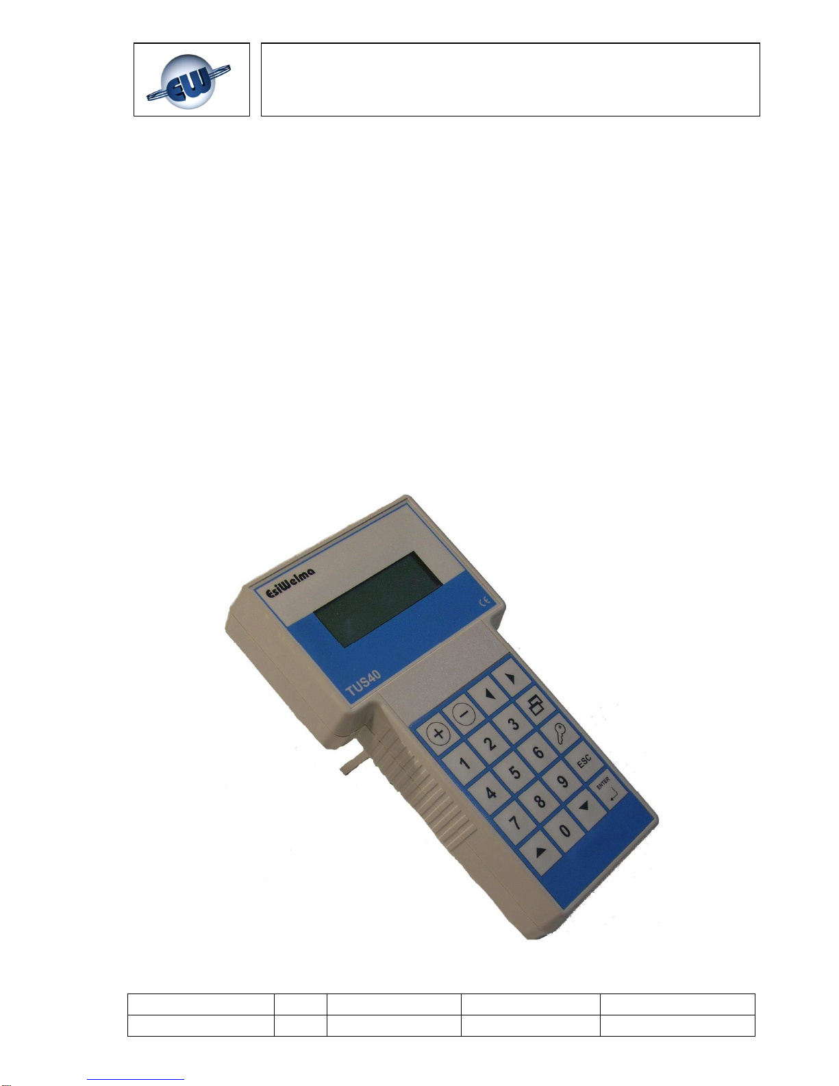
Terminal Unit
TUS40-20
INSTRUCTION MANUAL

Type / No.
Rev. Date Page Total pages
EW082.695_en 5 02 August 2010
2
28
EsiWelma
s.r.l.
CONTENTS
1 GENERAL
.................................................................................................................................................3
1.1 M
EANING OF SYMBOLS
.......................................................................................................................3
1.2 H
AZARDOUS GAS THRESHOLD
..........................................................................................................3
2 DESCRIPTION OF TERMINAL UNIT
..............................................................................................5
3 INSTALLATION
.......................................................................................................................................8
3.1 I
NSTALLATION OF THE
TUS40-20 T
ERMINAL UNIT
.......................................................................8
3.2 T
YPES OF DETECTOR INSTALLATION FOR CORRECT MONITORING
.............................................10
4 USING THE TERMINAL UNIT
..........................................................................................................11
4.1 O
PERATING MODES
..........................................................................................................................11
4.2 M
ONITORING MODE
...........................................................................................................................12
4.3 S
ETTING MODE
..................................................................................................................................13
4.4 C
ALIBRATION MODE
..........................................................................................................................14
4.5 C
ALIBRATING THE SENSOR
..............................................................................................................15
4.6 O
UTPUT TEST MODE
.........................................................................................................................18
4.7 4…20MA
SIGNAL CALIBRATION MODE
...........................................................................................19
4.8 T
ROUBLESHOOTING
..........................................................................................................................21
4.9 S
ENSOR OPERATION CHECK
............................................................................................................22
4.10 R
ESIDUAL LIFE
...............................................................................................................................23
4.11 C
HANGING THE CONTRAST ON THE DISPLAY
.............................................................................23
5 INSTALLATION DATA
........................................................................................................................24
6 ROUTINE CHECKS
.............................................................................................................................25

Type / No.
Rev. Date Page Total pages
EW082.695_en 5 02 August 2010
3
28
EsiWelma
s.r.l.
1 GENERAL
This chapter provides some information on the characteristics of the gases and on the
installation criteria for gas detection devices before the description of the TUS40-20 terminal
unit.
It is not essential to read this chapter to install and commission the terminal unit
described in this manual. Readers who already know the subject can skip this part.
1.1 Meaning of symbols
The symbols used in this manual have the following meaning:
• ppm: Parts Per Million of concentration of gas in the air
• L.E.L%: Lower Explosive Limit
• %VOL: concentration of gas measured in percentage by volume
• D: Detector
• t: threshold limit value
• Pr: pre-alarm threshold
• 1t: alarm threshold one
• 2t: alarm threshold two
• FA: fail
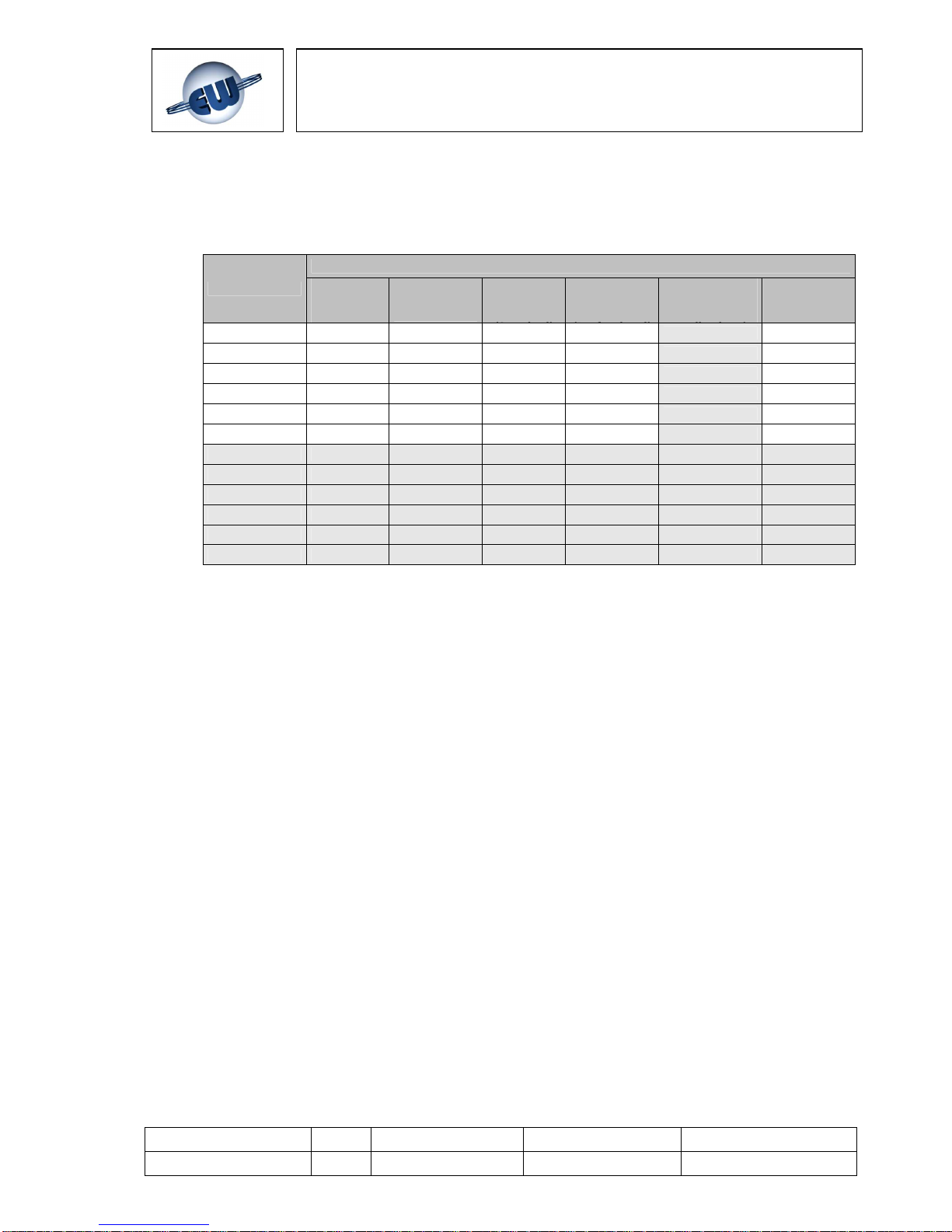
1.2 Hazardous gas threshold
For gases and for combustible vapours, the hazardous conditions begin from a threshold
called "Lower Explosive Limit" (LEL) that is the lowest concentration (percentage) of a gas
in air capable of producing a flash of fire in presence of an ignition source. This threshold
changes from gas to gas. The Lower Explosive Limits for some of the most common
gases are shown in the table below.
LEL (100%)
GAS ppm %VOL
METHANE (CH4) 50,000 5%
ISOBUTANE (iso-C4H10) 18,000 1.8%
BUTANE (C4H10) 18,600 1.86%
LPG 19,000 1.9%
HYDROGEN (H2) 40,000 4%
Table 1.1
For toxic gases such as carbon monoxide (CO), the hazard level must be considered also in
relation to the duration of the person's exposure in the polluted environment. The table
below shows risks from exposure to carbon monoxide (CO). Carbon monoxide is generated
wherever combustion occurs and the lungs rapidly absorb it and spread it through the
pulmonary alveolus where it reversibly binds with the haemoglobin as “carboxyhaemoglobin”
(COHb). It is also colourless and odourless so it is not naturally detected. This is why COspecific detection devices are necessary.
Type / No.
Rev. Date Page Total pages
EW082.695_en 5 02 August 2010
4
28
EsiWelma
s.r.l.
COHb in the bloodstream has the following effects on healthy adults.
% COHb EFFECTS
0.3-0.7 Normal amount in non-smokers from the endogenous production of CO
0.7- 2.9 No detectable symptoms
2.9-4.5 Cardiovascular disorders in patients suffering from heart disease
4-6 Usual levels in smokers, some physical impairment in psychomotor tests
7-10
Ailments in patients without heart disease (increase in cardiac output and in
blood flow in coronary arteries)
10-20 Slight headache, weakness, possible effect on foetus
20-30 Strong headache, nausea, loss of movement in hands
30-40
Strong headache, irritability, confusion, loss of vision, nausea, muscle
weakness, dizziness
40-50 Convulsions and loss of consciousness
60-70 Coma, respiratory arrest, death
Table 1.2
This issue is covered in other similar tables and a wide range of literature. In its document,
"Air quality for CO", the US department of Health, Education and Welfare refers to an
observed weakening in vision observed with 3% of COHb and in other psychomotor tests
with 5% of COHb.
More recently, subjects exposed to a dose of 100 ppm CO for one hour have shown a loss
of motor skills.
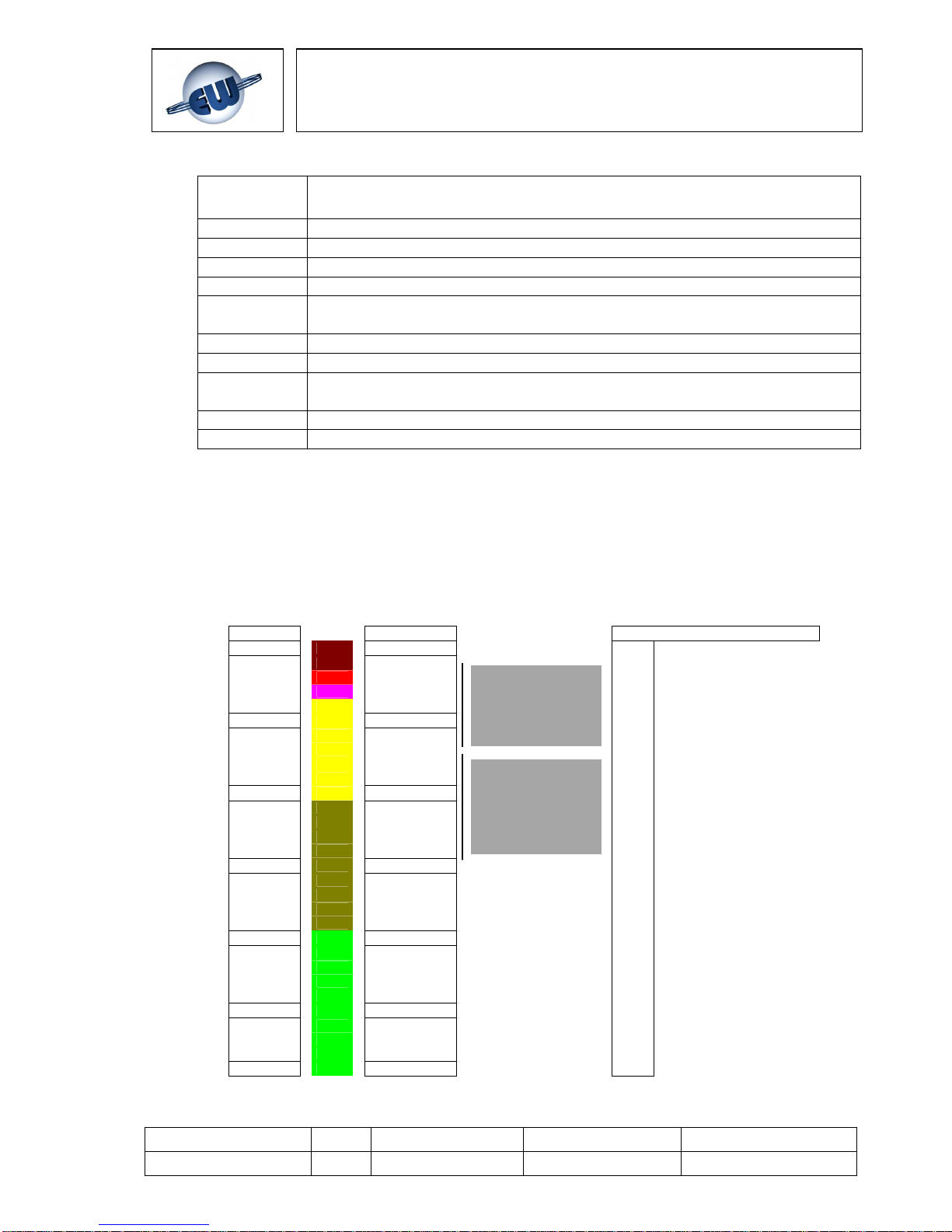
ppm % VOL LEL % (methane gas)
1,000,000
100
impossible combustion
100,000 10
100 Lower Explosive Limit
40
10,000 1
20
10
5
1,000 0.1
100 0.01
10 0.001
1 0.0001
Fig. 1.1
Possible combustion
range
Limit value range of
gas detectors
Type / No.
Rev. Date Page Total pages
EW082.695_en 5 02 August 2010
5
28
EsiWelma
s.r.l.
2 DESCRIPTION OF TERMINAL UNIT
The TUS40-20 is a terminal unit for monitoring and setting the UR.20. sensors and consists of:
theTUS40 handheld terminal
the UIC20 junction card
the 3m long CBL01 coiled cable
the two units communicate through a dedicated master protocol.
The TUS40-20 terminal unit is necessary when a mobile monitoring system is required and/or
for different settings of the gas detection threshold limit values from the ones that can be set
using the DIP switch; it is also necessary for recalibrating sensors if standard factory
calibration gas cylinders are not used.
NOTE: the words "detector" and "sensor" are used without distinction throughout this document
and have the same meaning, except where this may create ambiguity.
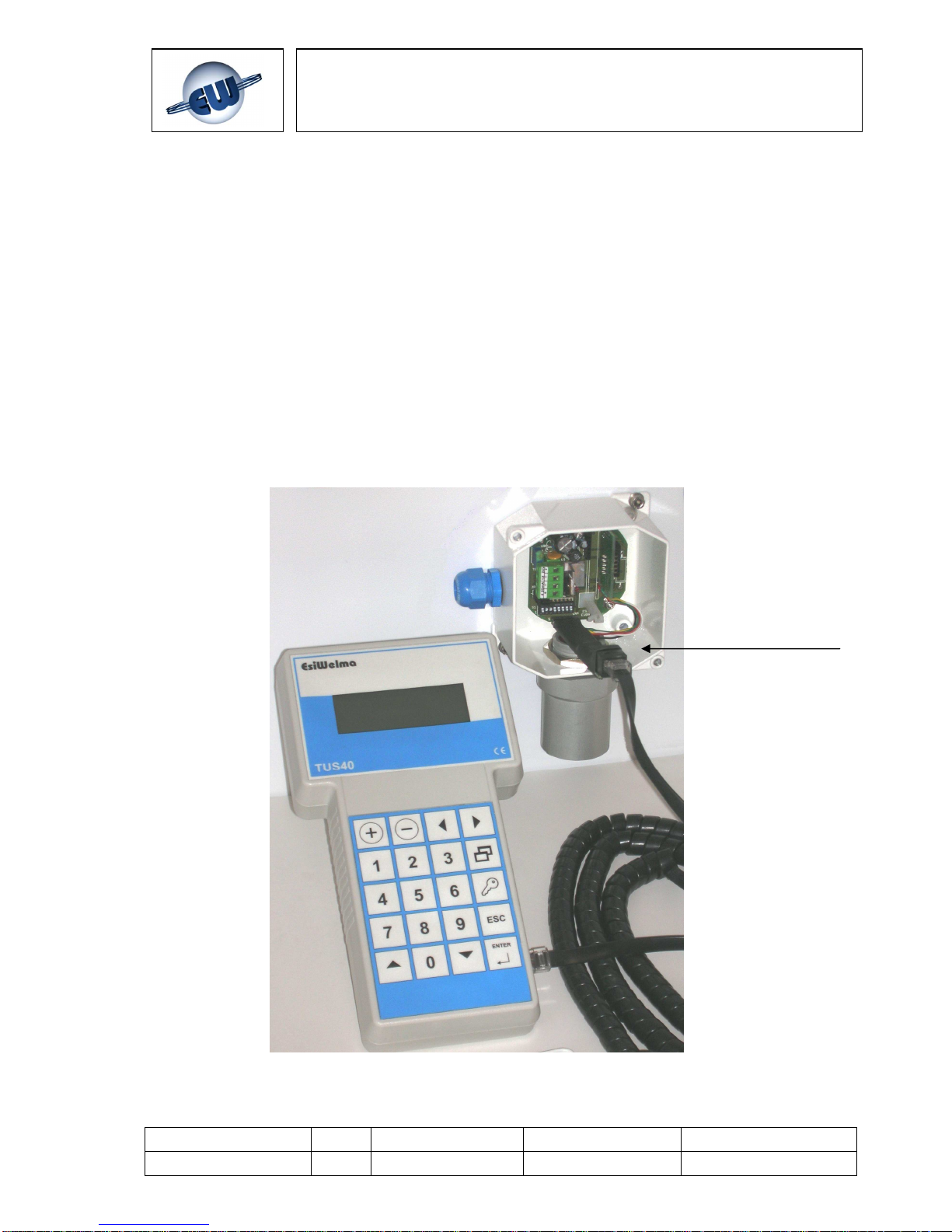
The system structure is shown in Fig. 2.1.
Fig. 2.1 –
Terminal unit for monitoring and setting UR.20.. sensors
Handheld
terminal
Junction
card
Coiled cable
Type / No.
Rev. Date Page Total pages
EW082.695_en 5 02 August 2010
6
28
EsiWelma
s.r.l.
Under normal operating conditions (monitoring) the handheld terminal receives the information
relating to measurements taken by the detector and the alarm status established by the
threshold limit values. Three threshold limit values and one fail condition can be defined, and
they are respectively called:
• pre-alarm: Preall.
• alarm threshold one: Treshold1
• alarm threshold two: Treshold2
• device failure: Fail
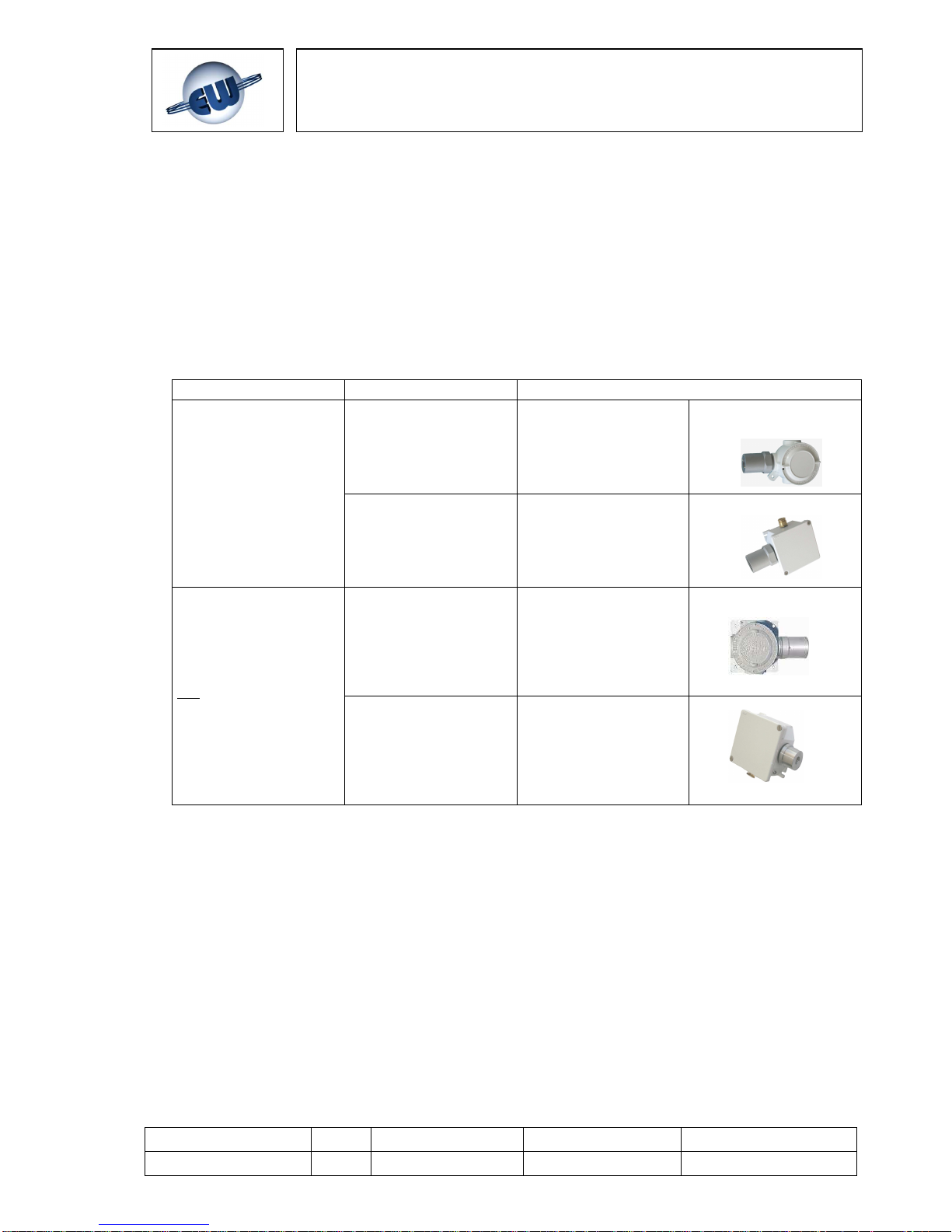
The UR.20.. detectors come in four models (E, S, I, L) and their use depends on the protection
mode required:
Application Protection mode Part number
Classified (hazardous)
areas
(ATEX certification
required)
Group II
Category 2G
Ex d IIC T6
T
AMB
: -20 °C ÷ +50 °C
UR.20.E
Group II
Category 3G
Ex nA d IIC T6
T
AMB
: -20 °C ÷ +50 °C
UR.20.S
Unclassified (nonhazardous) areas
(ATEX certification is
not required)
Heavy-duty applications
Construction conforming to
Ex d requirements
IP65
UR.20.I
Standard applications
Construction conforming to
Ex nA requirements
IP55
UR.20.L
Tab.2.1 – Gas sensors: available models
In turn, each model (E, S, I, L) has two possible executions:
• with Standard sensor (code S: UR.20S.)
• with Professional sensor (code P: UR.20P.)
Two types of sensors are commonly used for the gases that most frequently require detection
(methane, LPG, gasoline vapours, carbon monoxide etc.): catalytic (Pellistor) and
electrochemical cell. In both cases, the Professional execution is differentiated from the
Standard execution by the use of sensors that are based on the same operating principle as
the others but that over time have more measurement stability and higher poison resistance to
the continuous presence of gas.
Type / No.
Rev. Date Page Total pages
EW082.695_en 5 02 August 2010
7
28
EsiWelma
s.r.l.
As you can see in the table below, the part number includes several fields for rapid
identification in order to facilitate the choice of the detector according to the technical features
described above:
Available
models
Models on
request
For other Gases, on request, please contact Customer Service.
Detectable Gas
Sensing Element
Standard
Catalytic
Pellistor
Catalytic
(Professional)
2-terminal
Electr.
Cell
3-terminal
Electr.
Cell
Semiconductor
(1 or 2-
thresholds
Non
Dispersive
infrared
Methane URG20SL URG20PL --- --- URG20TL --LPG URP20SL URP20PL --- --- URP20TL --CO --- --- URO20SL URO20PL URO20TL ---
Gasoline
URB20SL URB20PL --- --- URB20TL --O2 --- --- URS20SL --- --- --CO2 --- --- --- --- --- URD20SL
Acetylene URL20SL URL20PL --- --- URL20TL
Hydrogen URI20SL URI20PL --- --- URI20TL
Ammonia URM20SL URM20PL --- --- URM20TL
Propane URC20SL URC20PL --- --- URC20TL
Octane URT20SL URT20PL --- --- URT20TL
Ethyl Alcohol URE20SL URE20PL --- --- URE20TL
Tab. 2.2 – Gas detector part numbers
Type / No.
Rev. Date Page Total pages
EW082.695_en 5 02 August 2010
8
28
EsiWelma
s.r.l.
3 INSTALLATION
3.1 Installation of the TUS40-20 Terminal Unit
The TUS40 handheld terminal is constructed in plastic housing and it plugs into the junction
box via the coiled cable to be powered by the UR.20.. sensor.
A fold-out bar on the back of the TUS40 handheld terminal can be used to place it at a
convenient tilt on a minimum surface area of 220x130 mm. Knurling at the sides of the
keypad ensures an easy and secure grip.
The TUS40-20 terminal unit must be connected with the sensor power off; follow product
and/or installation instructions before opening the sensor cover. Proceed as follows to
connect the TUS40-20 terminal unit:
1. Make sure the area is clear of gas and that the sensor is not powered up
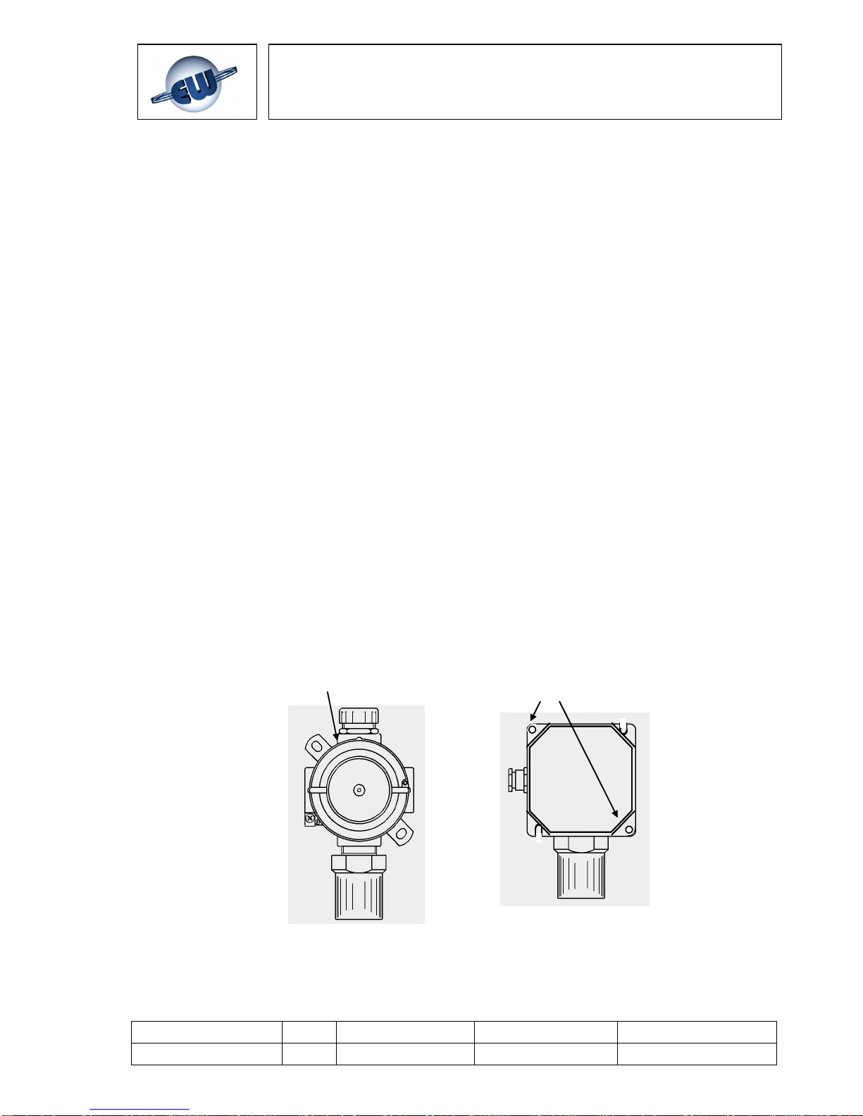
2. Open the UR.20 sensor cover (Fig.3.1)
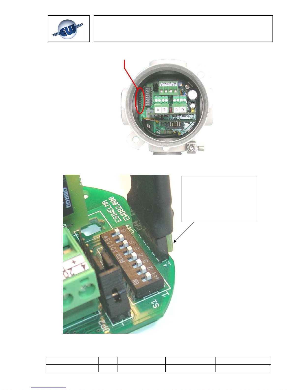
3. Identify the position of the CN4 connector on the diagram (Fig. 3.2)
4. Plug the junction card into the socket, making sure it is properly lined up with the
contacts (Fig. 3.3), then plug the cable and handheld terminal into the junction card
RJ45 connector.
5. Power up the sensor
6. Wait for the handheld terminal display to switch on; it will show a row of asterisks,
followed by the sensor status page (Fig. 4.1 and 4.2)
7. Wait for the end of the warm-up phase (preheating, Fig. 4.3)
8. The handheld terminal will then show the basic display (Monitoring Mode).
It is now possible to operate with the handheld terminal (Fig. 4.4).
The direction of the detector must always have the sensor facing downwards
Fig. 3.1 – Removing the cover of the UR20 sensors
Turn the screw cover
anticlockwise
Remove the fastening
screws of the cover
Type / No.
Rev. Date Page Total pages
EW082.695_en 5 02 August 2010
9
28
EsiWelma
s.r.l.
CN4 connection
Fig. 3.2 – CN4 position
Fig. 3.3 – TUS40 terminal plug-in operation
Warning:
Properly align the female and
male CN4 connector with the
PCB side of the UIC20 junction
card to the outside of the main
board of the sensor.
 Loading...