

Page 1

Smart-2 Multi Functional Wireless Weighing Indicator Indicator
User Manual
Page 2

Smart-2 Multi Functional
Wireless Weighing Indicator
User Manual
Page 3

________________________________________________________________________________________________
SMART-2 Multi Functional Wireless Weighing Indicator User Manual
TABLE O F CONTENTS
35TLEGAL WARNING35T ................................................................................................................................ 4
35TGENERAL DETAILS35T .............................................................................................................................. 5
35TMOUNTING METHODS35T ....................................................................................................................... 6
35TINDICATORS35T ........................................................................................................................................ 7
35TINDICATOR CONNECTIONS35T................................................................................................................. 7
35TMENU SYSTEM35T ................................................................................................................................... 8
35TDEVICE IDENTITY INFORMATION35T ..................................................................................................... 10
35TDISPLAYING THE SERIAL NUMBER35T ............................................................................................... 10
35TDISPLAYING THE VERSION DETAILS35T .............................................................................................. 10
35TDISPLAY SETTINGS:35T ........................................................................................................................... 11
35TSETTING THE POINT LOCATION35T .................................................................................................... 11
35TINCREMENT STEP SETTING35T ........................................................................................................... 12
35TWEIGHING CAPACITY SETTING35T ..................................................................................................... 13
35TUNIT OF MEASUREMENT SETTING35T ............................................................................................... 14
35TCONFIGURATION SETTINGS35T ............................................................................................................. 15
35TDISPLAY LIGHT SETTING35T ............................................................................................................... 15
35TAVERAGE SETTING35T........................................................................................................................ 16
35TWEIGHT CHANGE SPEED35T .............................................................................................................. 17
35TECO MODE SETTING35T ..................................................................................................................... 18
35TGAIN SETTING35T ............................................................................................................................... 19
35TDISPLAY BRIGHTNESS SETTING35T .................................................................................................... 20
35TMEASUREMENT STABILITY35T ........................................................................................................... 21
35TWEIGHT CALIBRATION35T ..................................................................................................................... 22
35TZERO CALIBRATION35T ...................................................................................................................... 22
35TLOAD CALIBRATION35T ...................................................................................................................... 23
35TRELAY SETTINGS35T ............................................................................................................................... 24
35TRELAY 1 SETTINGS35T ........................................................................................................................ 25
35TRELAY 1 SET VALUE SETTING35T .................................................................................................... 25
35TRELAY 1 SET DIRECTION SETTING35T ............................................................................................. 26
35TRELAY 1 SET HYSTERESIS SETTING35T ............................................................................................ 27
35TRELAY 1 DELAY TIME SETTING35T .................................................................................................. 28
35TRELAY 2 SETTINGS35T ........................................................................................................................ 29
35TANALOG OUTPUT (DAC) SETTINGS35T .................................................................................................. 30
35TANALOG OUTPUT CALIBRATION35T .................................................................................................. 30
35TDAC LOWEST OUTPUT VALUE (LVAL) SETTING35T ............................................................................ 31
Page 1
Page 4

________________________________________________________________________________________________
SMART-2 Multi Functional Wireless Weighing Indicator User Manual
35TDAC HIGHEST OUTPUT VALUE (HVAL) SETTING35T ........................................................................... 32
35TDAC MAXIMUM OUTPUT (DMAX) VALUE SETTING35T ..................................................................... 33
35TCOMMUNICATION SETTINGS35T ........................................................................................................... 34
35TCOMMUNICATION MODE SETTING35T ............................................................................................. 34
35TINDICATOR ADDRESS (SCALE IDENTITY NO) SETTING35T .................................................................. 35
35TCOMMUNICATION PARITY BIT SETTING35T ...................................................................................... 36
35TCOMMUNICATION SPEED (BAUD RATE) SETTING35T ....................................................................... 37
35TCOMMUNICATION DATA LENGTH SETTING35T ................................................................................. 38
35TPOINT-TO-POINT COMMUNICATION SETTING35T ............................................................................ 39
35TBLUETOOTH SETTINGS35T ..................................................................................................................... 41
35TBLUETOOTH STATUS SETTING35T ...................................................................................................... 41
35TBLUETOOTH ID SETTING35T ............................................................................................................... 42
35TWIFI SETTINGS35T .................................................................................................................................. 43
35TWIFI STATUS SETTING35T .................................................................................................................. 43
35TWIFI MODE SETTING35T .................................................................................................................... 44
35TWIFI Access Point ID SETTING35T ...................................................................................................... 45
35TWIFI Station ID SETTING35T ............................................................................................................... 46
35TWIFI Name SETTING35T ..................................................................................................................... 47
35TTEMPERATURE CALIBRATION SETTINGS35T .......................................................................................... 48
35TRESTORING FACTORY SETTINGS35T ...................................................................................................... 49
35TPERFORMING TARING WITH key35T .......................................................................................... 50
35TRESETTING DISPLAY VALUE WITH KEY35T .................................................................................. 50
35TCONNECTIONS AND MODE SELECTIONS35T .......................................................................................... 51
35TCALIBRATION SWITCH (P2)35T .......................................................................................................... 51
35TANALOG OUTPUT mode selection35T ............................................................................................... 52
35T0-5V analog output connection35T ............................................................................................... 52
35T4-20mA analog output connection35T .......................................................................................... 52
35TANDROID APPLICATION SETTINGS35T ................................................................................................... 53
35TCONNECTION WITH WIFI MODULE35T .............................................................................................. 53
35TCONNECTION WITH BLUETOOTH MODULE35T ................................................................................. 55
35TMAKING DEVICE SETTINGS35T ........................................................................................................... 57
35TDisplay Settings35T ........................................................................................................................ 57
35TConfiguration Settings35T .............................................................................................................. 58
35TRelay Settings35T ........................................................................................................................... 58
Page 2
Page 5

________________________________________________________________________________________________
35TERROR CODES35T ................................................................................................................................... 64
SMART-2 Multi Functional Wireless Weighing Indicator User Manual
35TAnalog Output (DAC) Settings35T .................................................................................................. 58
35TCommunication Settings35T .......................................................................................................... 59
35TWifi Connection Setting35T ........................................................................................................... 59
35TCalibration Setting35T .................................................................................................................... 61
35TTemp Calibration Setting35T .......................................................................................................... 63
Page 3
Page 6

________________________________________________________________________________________________
SMART-2 Multi Functional Wireless Weighing Indicator User Manual
LEGAL WARNING
We congratulate you on the good choice you made. ESIT SMART-2 indicators are
Esit's simplest w eight indicators which are special ly designed in li ne with your w eight
measurement needs.
SMART-2 is an ideal device with its features for the weighing sector with its unique
durable construction and the unusually small dimensions Like the ESIT's other
indicators, SMART-2 is manufactured to provide the most advanced quality
standards.
This user guide is pre pared to intr oduce featur es of SMAR T-2 to our valuable user s
and help you get the most out of your device.
For more information and technical support, please visit 35Twww.esit.com.tr 35T.
Page 4
Page 7
________________________________________________________________________________________________
SMART-2 Multi Functional Wireless Weighing Indicator User Manual
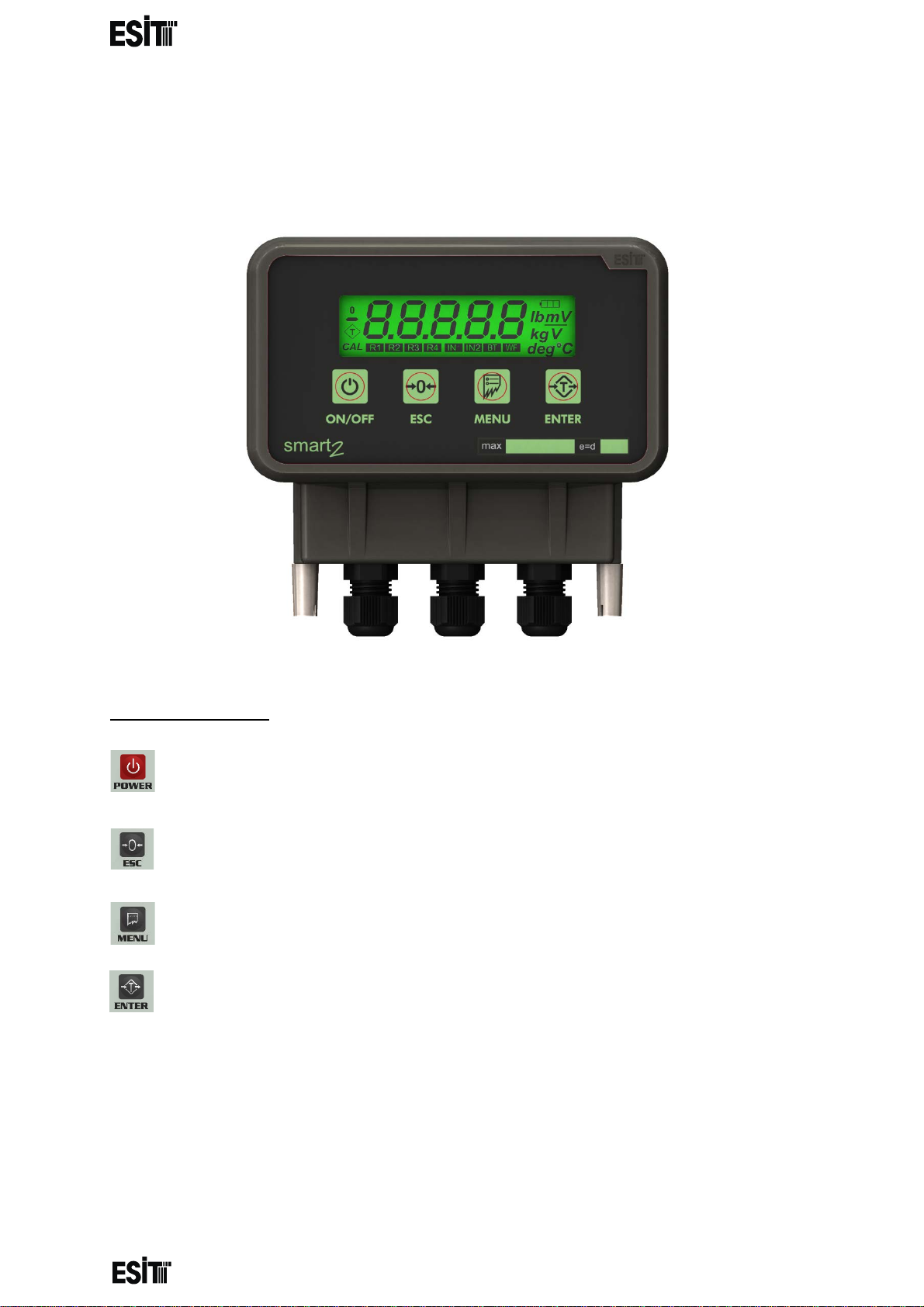
GENERAL DETAILS
Loadcell Cable Input Power, Communication, Relay, DAC Cables
key Function
Switch on / off the device
Going one level up in the menu and resetting while in the weight display
Access to menu
Menu selection, confirmation and taring while in the weight display
Page 5
Page 8
________________________________________________________________________________________________
SMART-2 Multi Functional Wireless Weighing Indicator User Manual
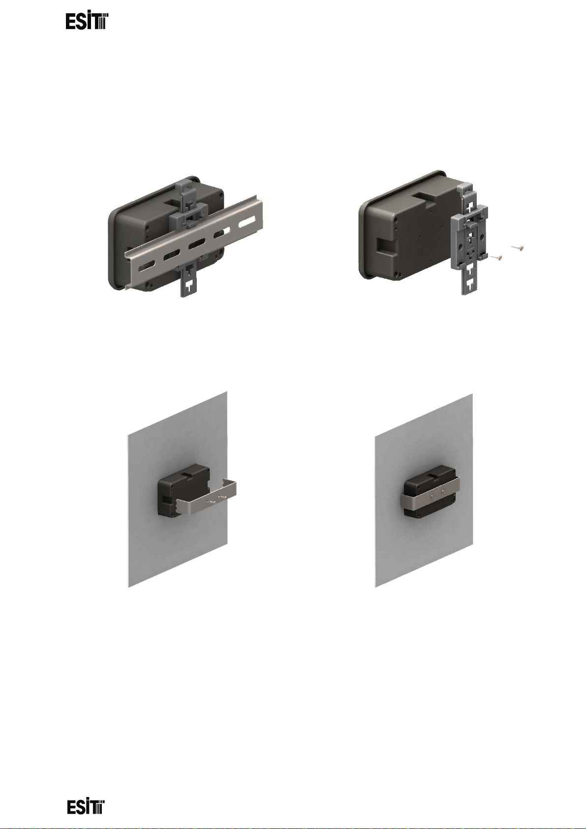
MOUNTING METHODS
• Rail Mounting Apparatus (inside cabinet or wall mounting)
• Panel Mounting Apparatus (Front panel mo u nt ing)
Page 6
Page 9
1 2 3 4 5 6 7 8 9
10
11
12
13
14
15
16
17
18
19
20
21
-LC 1 input
+LC 1 input
-LCFeed +LCFeed
LCGround
0V GND
+V (6-24V)
-Io +Io
+Vo
GND
DI2
DI1
RL 2/1
RL 2/2
RL 1/1
RL 1/2 RS485VCC
Rx / B Tx / A RS485GND
________________________________________________________________________________________________
SMART-2 Multi Functional Wireless Weighing Indicator User Manual
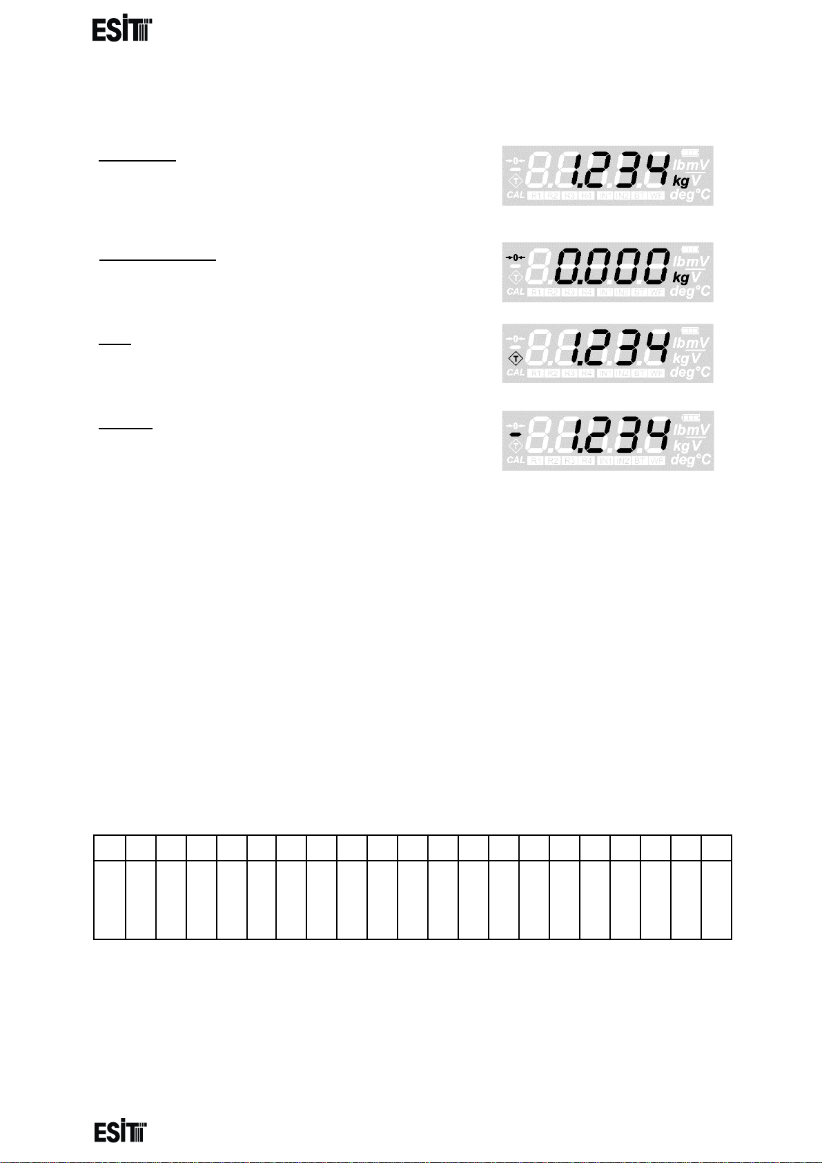
INDICATORS
UInactivity:U The display value indicates that
inactivity has been d etected within ±2e rang e for 2
seconds and kg segment is highlighted on the
display. (e: incremen t s tep on the di s play)
UAbsolute zero:U Indicates that display value is 0
and internal counting value is less than 1/4e.
UNet:U Indicates taring operation is in
progress
UMinus:U In dicates that the display value is negativ e.
INDICATOR CONNECTIONS
In the printed circuit of the indicator, the connections are as follows provided that
the leftmost terminal slot is number 1. See 'Connection and mode selection'
section for more details .
Page 7
Page 10
________________________________________________________________________________________________
SMART-2 Multi Functional Wireless Weighing Indicator User Manual
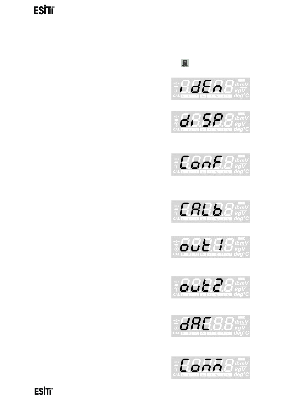
MENU SYSTEM
To access the menu system and navigat e menus, press the button
IDENTITY MENU: This is the menu for
displaying the serial number and version
information of the indic ator .
DISPLAY SETTINGS MENU: Th is is the men u
where the increment step (e), point location,
weighing capacity value and unit of
measurement are set.
CONFIGURATION MENU: This is the menu
where background light setting, brightness,
average filter size, eco mode, weight change
response speed, weight tracking and ADC gain
value settings are made.
CALIBRATION MENU: This is the menu wher e
zero and load calibrations are made.
OUT 1 (RELAY # 1) MENU: T his is the menu
where set value, hysteresis, delay time and
contact position setting for relay 1 are
performed.
OUT 2 (RELAY # 2) MENU: T his is the menu
where set value, hysteresis, delay time and
contact position setting for relay 2 are
performed.
ANALOG OUTPUT (DAC) MENU: This is the
menu for setting l ower and upp er values a nd the
display values corresponding to the lower value
for the analogue output.
COMMUNICATION SETTINGS MENU:
This is the menu where the communication mode,
speed and data format settings are made.
Page 8
Page 11
________________________________________________________________________________________________
SMART-2 Multi Functional Wireless Weighing Indicator User Manual
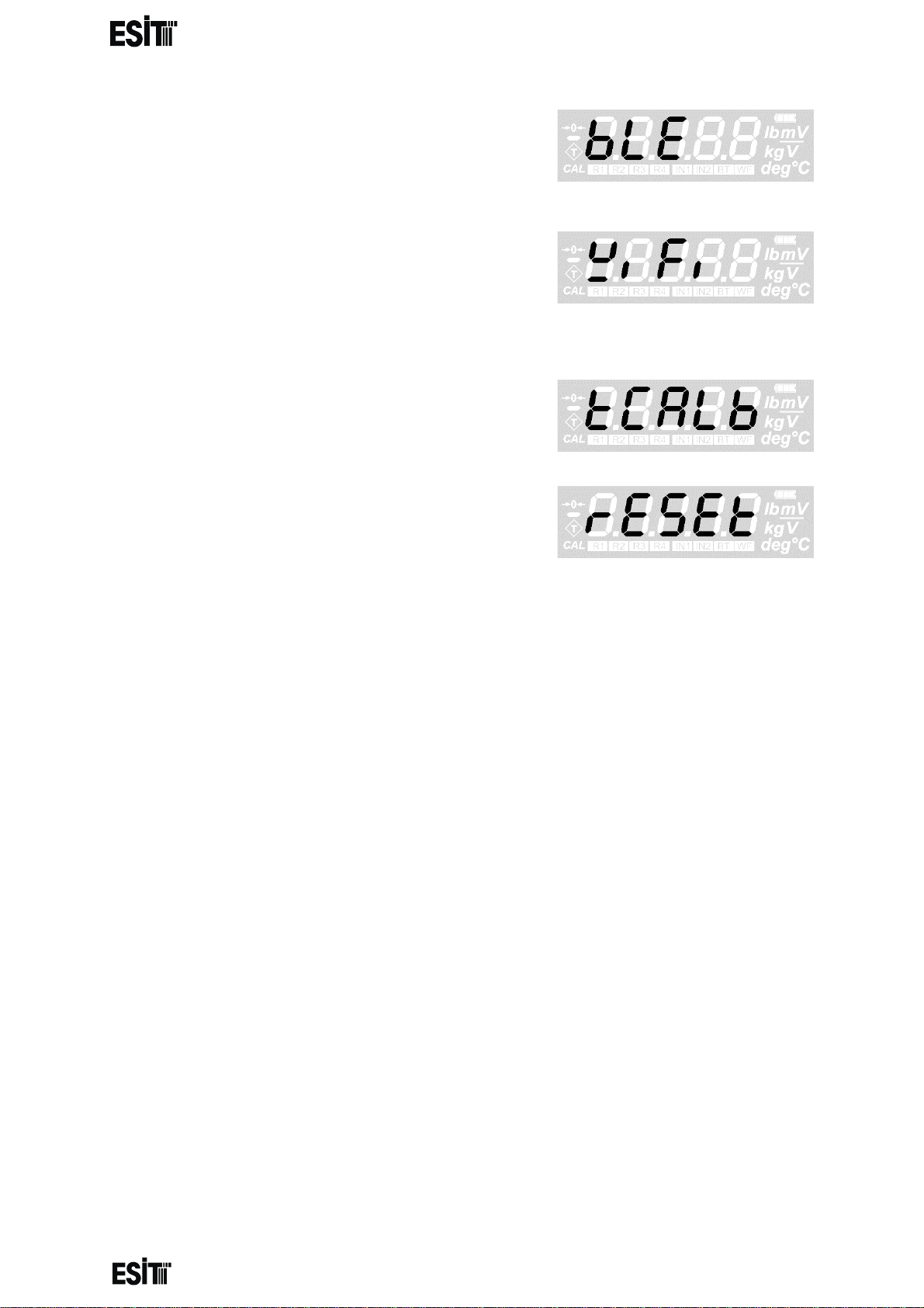
BLUETOOTH MENU: This is the menu for making
the name setting and on/off setting of the Bluetooth
Low Energy module. The module becomes active
when it is connected to the device.
WIFI MENU: This is the menu for making the name
setting and on/off setting of the WiFi module. The
module becomes active when it is connected to the
device.
TEMPERATURE CALIBRATION MENU: This
is the calibration menu for temperature
compensation.
RESET MENU: It is used to restore the factory
settings.
Page 9
Page 12
________________________________________________________________________________________________
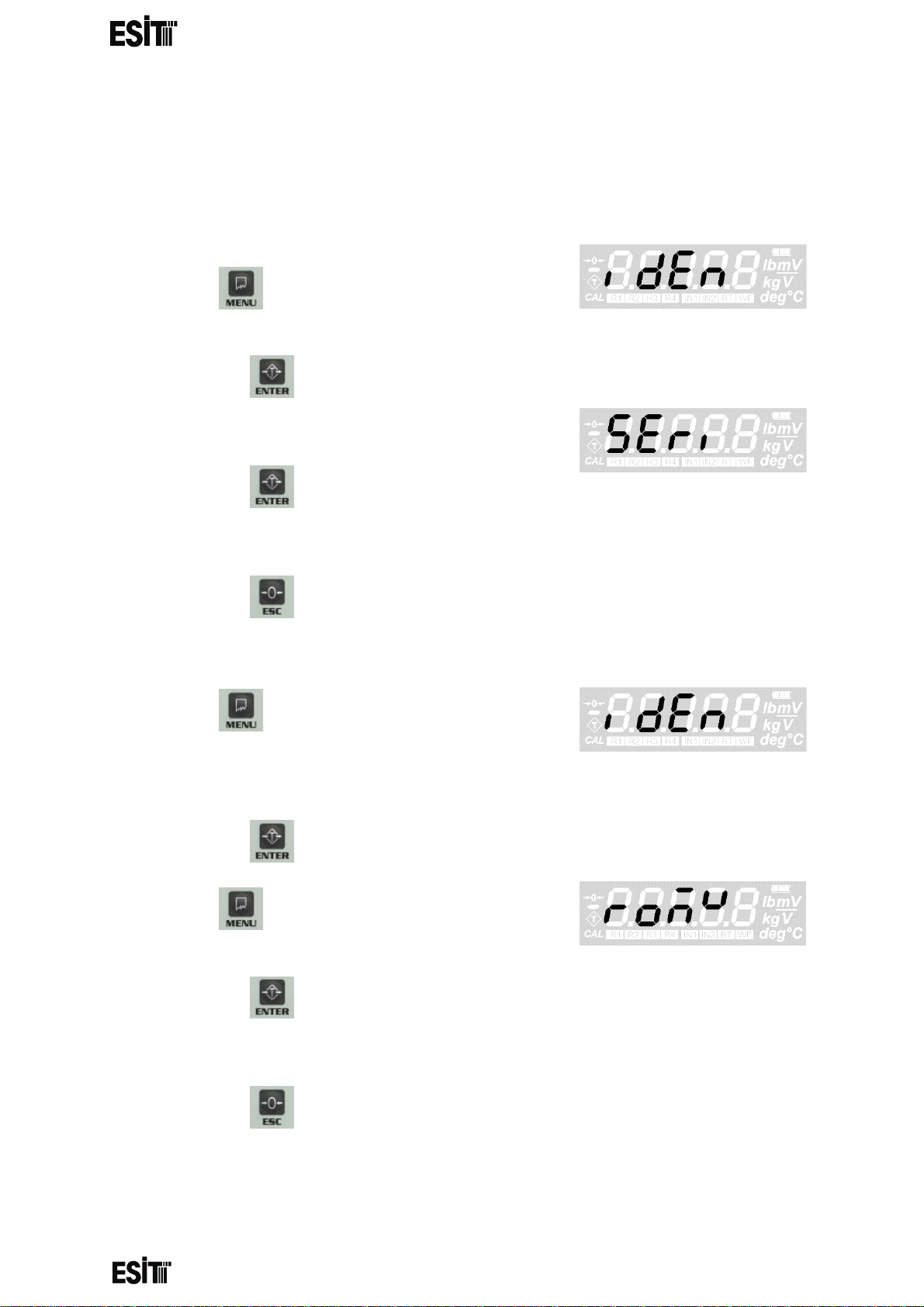
DEVICE IDENTITY INFORMATION
SMART-2 Multi Functional Wireless Weighing Indicator User Manual
It is possible to display the serial number and version information of the
indicator with this menu.
DISPLAYING THE SERIAL NUMBER
1. Press key until you reach the 'Device
identity information' menu
2. Press the key to confirm the menu
3. The first option is the 'Serial number' menu.
4. Press the key to confirm the menu
5. The value displayed on the screen is the serial number of the indicator
6. Press the key to go back to the measurement screen.
DISPLAYING THE VERSION DETAILS
7. Press key until you reach the 'Device
identity informatio n me nu
8. Press the key to confirm the menu
9. Press key until you reach the 'Version
Details' menu
10. Press the key to confirm the menu
11. The value displayed on the screen is the version details of the indicator
12. Press the key to go back to the measurement screen.
Page 10
Page 13
________________________________________________________________________________________________
SMART-2 Multi Functional Wireless Weighing Indicator User Manual
DISPLAY SETTINGS:
WARNING: In order for thes e menu functi ons to be ac tive, the P 2 connectio n inside
the indicator must be open circuit; otherwise only recorded information will be
displayed and they are not allow ed to be chan ged. In thi s case, a speci al error cod e
(Error50) will also be displayed on the indicator's screen.
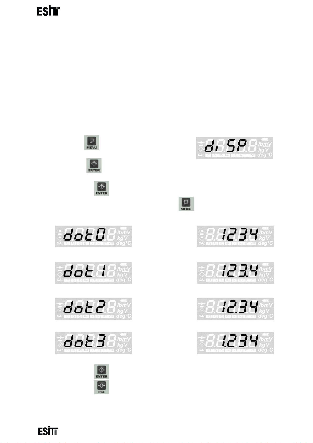
SETTING THE POINT LOCATION
If a decimal representation of the screen resolution is required, the decimal point is
set with this menu.
(1) Press key until you reach the 'Display
Settings' menu
(2) Press the key to confirm the menu
(3) The first option is the 'Decimal point' menu.
(4) Press the key to confirm the menu
(5) Set the decimal point as you desire with menu key.
then
if
then
if
then
if
then
if
(6) Press the key to save the changes.
(7) Press the key to go back to the measurement screen.
Page 11
Page 14
________________________________________________________________________________________________
SMART-2 Multi Functional Wireless Weighing Indicator User Manual
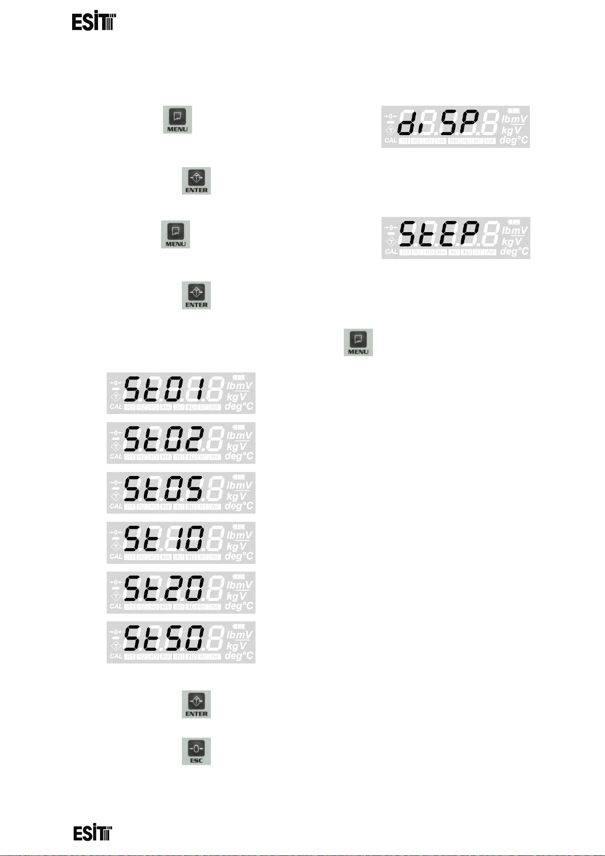
INCREMENT STEP SETTING
(1) Press key until you reach the 'Display
Settings' menu
(2) Press the key to confirm the menu
(3) Press key until you r each the 'Inc rement
Step' menu
(4) Press the key to confirm the menu
(5) Set the increment step as you desire with menu key.
then e = 1
if
then e = 2
if
then e = 5
if
then e = 10
if
then e = 20
if
then e = 50
(6) Press the key to save the changes.
(7) Press the key to go back to the measurement screen.
Page 12
Page 15
________________________________________________________________________________________________
SMART-2 Multi Functional Wireless Weighing Indicator User Manual
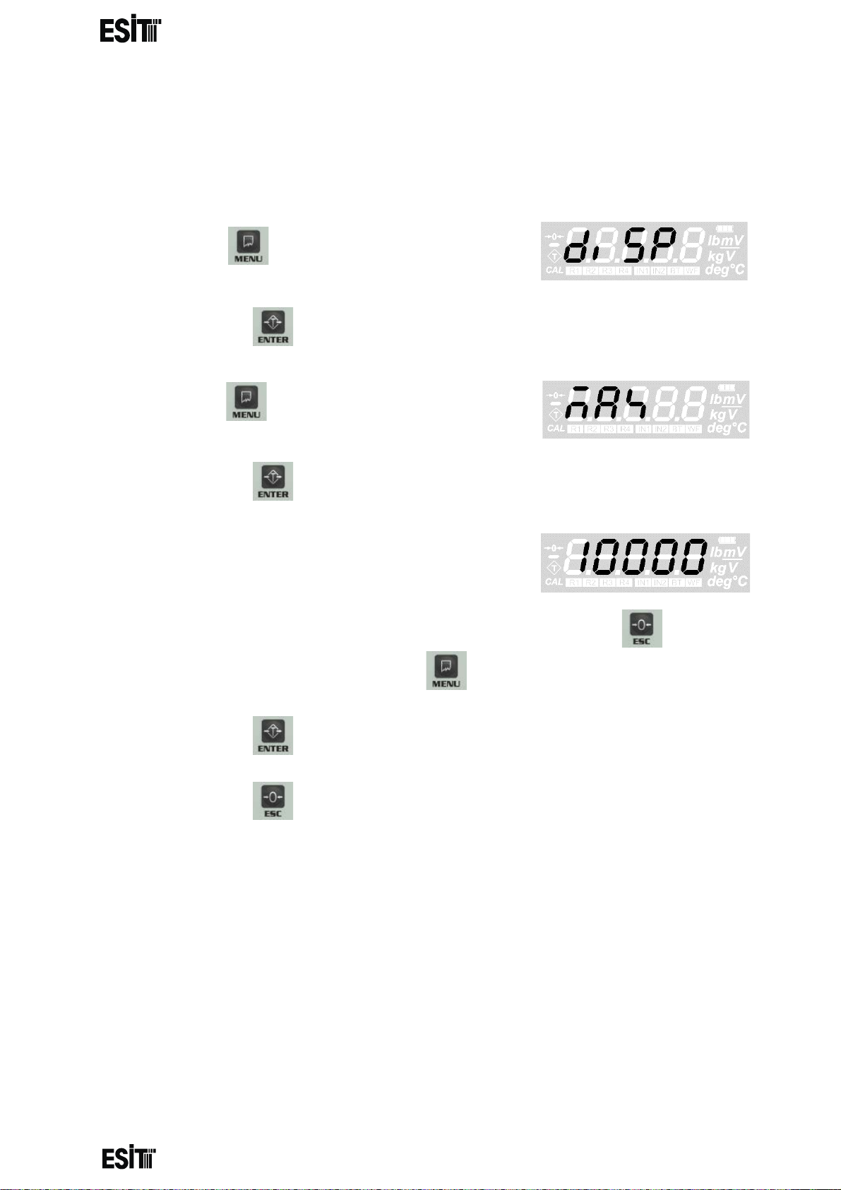
WEIGHING CAPACITY SETTING
This value is the maximum measurement value allowed to be displayed on
the screen. The indicator displays an error code if there is a load that
exceeds MAX (9e) value on the platform.
(1) Press key until you reach the 'Display
Settings' menu
(2) Press the key to confirm the menu
(3) Press key until you reach the 'Weighing
capacity' menu
(4) Press the key to confirm the menu
(5) The last recorded weighing capacity will be
displayed on the screen and the ten thousands
digit blinks at the same time
(6) Numeric value of the blinking digit can be increased with key. The
place value can be changes with key.
(7) Press the key to save the weighing capacity.
(8) Press the key to go back to the measurement screen.
Page 13
Page 16
________________________________________________________________________________________________
SMART-2 Multi Functional Wireless Weighing Indicator User Manual
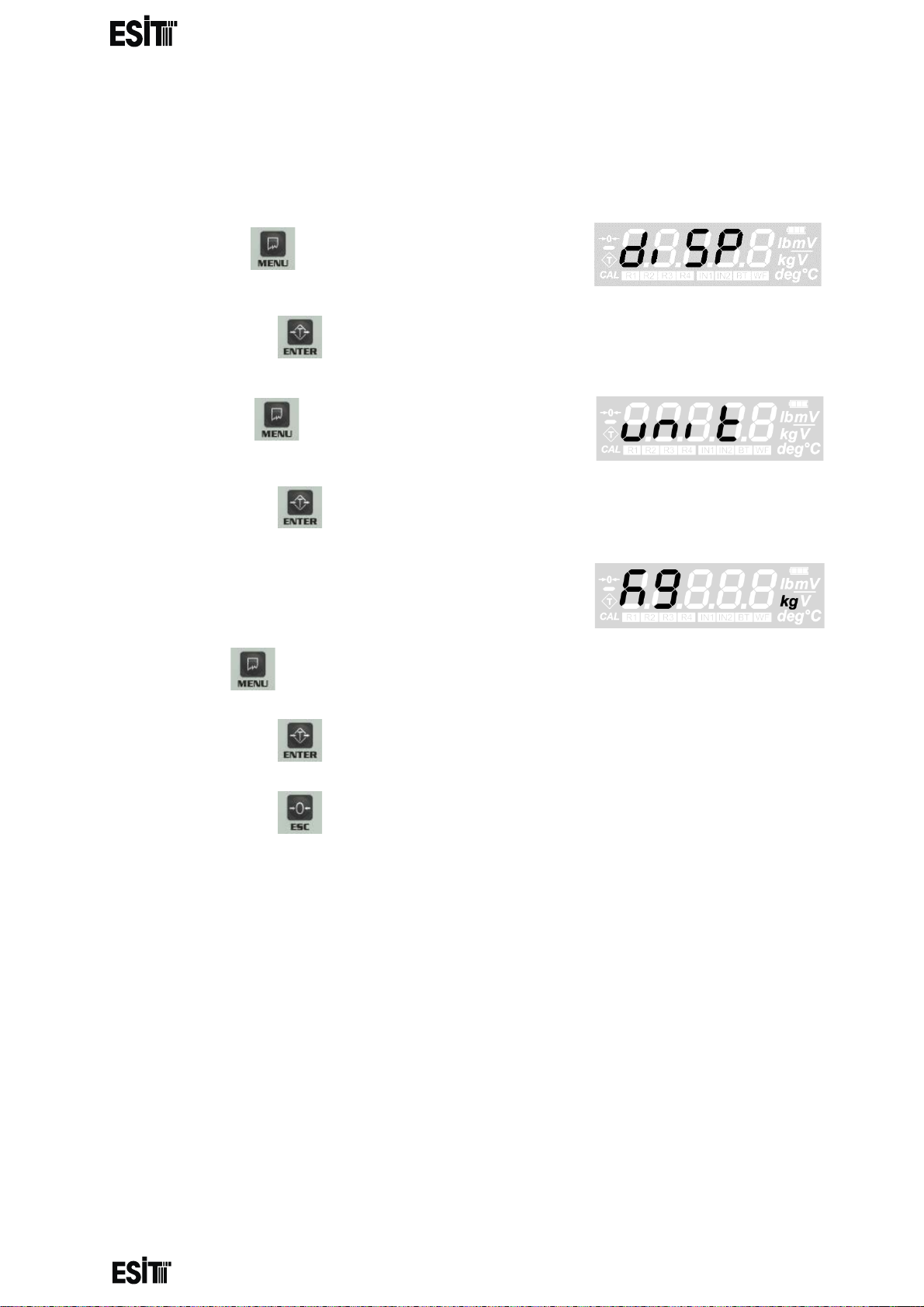
UNIT OF MEASUREMENT SETTING
This value allow s you to s elect the unit o f mea surement made. Kg , g, lb, ° C, deg rees,
mV / V, mV and V units can be selected.
(1) Press key until you reach the 'Display
Settings' menu
(2) Press the key to confirm the menu
(3) Press key until you reach the 'Unit
Settings' menu
(4) Press the key to confirm the menu
(5) The last used unit will be displayed on the
screen and the unit option on the right of the
screen will also be active at the same time.
(6) Press key until the unit you'd like to use is displayed on the screen.
(7) Press the key to save the unit setting.
(8) Press the key to go back to the measurement screen.
Page 14
Page 17
________________________________________________________________________________________________
SMART-2 Multi Functional Wireless Weighing Indicator User Manual
CONFIGURATION SETTINGS
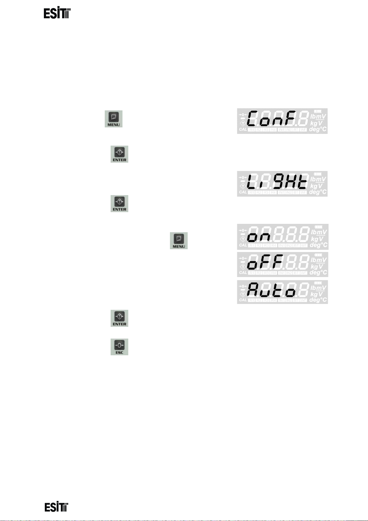
DISPLAY LIGHT SETTING
You can adjust the display light in this menu. In addition to the continuous on and off
options, you can also set the auto light on when the weight value changes by ±5e.
(1) Press key until you reach the
'Configuration Settings' menu
(2) Press the key to confirm the menu
(3) The first option is the 'Display light' menu.
(4) Press the key to confirm the menu
(5) Press ‘ON’ button to turn on, ‘OFF’ button to
turn off the display light and key until the
'Auto' screen is displayed for the auto mode.
(6) Press the key to save the display light setting.
(7) Press the key to go back to the measurement screen.
Page 15
Page 18
________________________________________________________________________________________________
SMART-2 Multi Functional Wireless Weighing Indicator User Manual
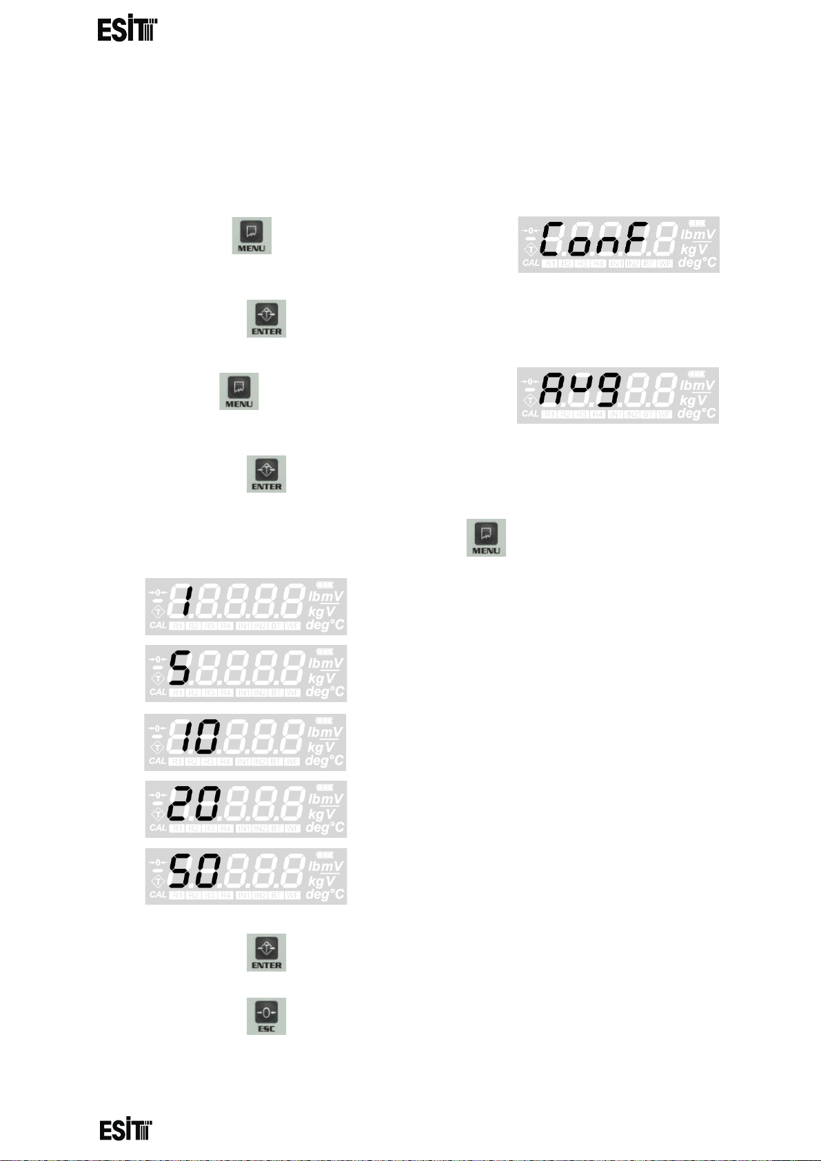
AVERAGE SETTING
With this value, the number of measurements to be averaged when the
measurement value is displayed on the screen is set. The high average value
increases the measurement quality while the response to small changes is reduced.
(1) Press key until you reach the
'Configuration Settings' menu
(2) Press the key to confirm the menu
(3) Press key until you reach the 'Average'
menu
(4) Press the key to confirm the menu
(5) Set the increment step as you desire with menu key.
if
then single measurement display
if
then average with 5 measurements
if
then average with 10 measurements
if
then average with 20 measurements
if
then average with 50 measurements
(6) Press the key to save the changes.
(7) Press the key to go back to the measurement screen.
Page 16
Page 19
________________________________________________________________________________________________
SMART-2 Multi Functional Wireless Weighing Indicator User Manual
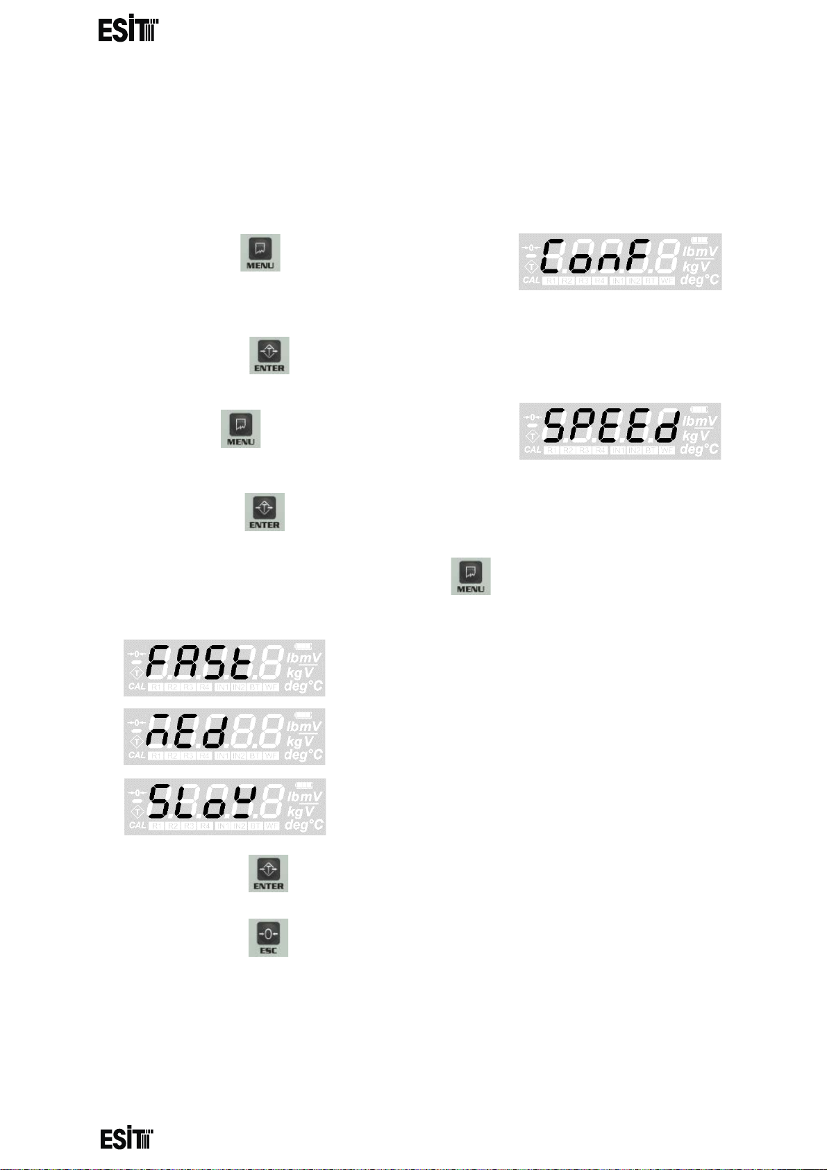
WEIGHT CHANGE SPEED
With this menu (SPEED), the speed of change when new weight is added, is
adjusted
It is 0.2 sec when FAST, 0.5 sec with MED, 1.0 sec with SLOW. The measurements
in the SLOW mode are more stable.
(1) Press key until you reach the
'Configuration Settings' menu
(2) Press the key to confirm the menu
(3) Press key until you reach the 'SPEED'
menu
(4) Press the key to confirm the menu
(6) Set the speed mode of your choice with menu key.
then 0.2 sec
then 0.5 sec
then 1.0 sec.
(6) Press the key to save the changes.
(7) Press the key to go back to the measurement screen.
Page 17
Page 20
________________________________________________________________________________________________
SMART-2 Multi Functional Wireless Weighing Indicator User Manual
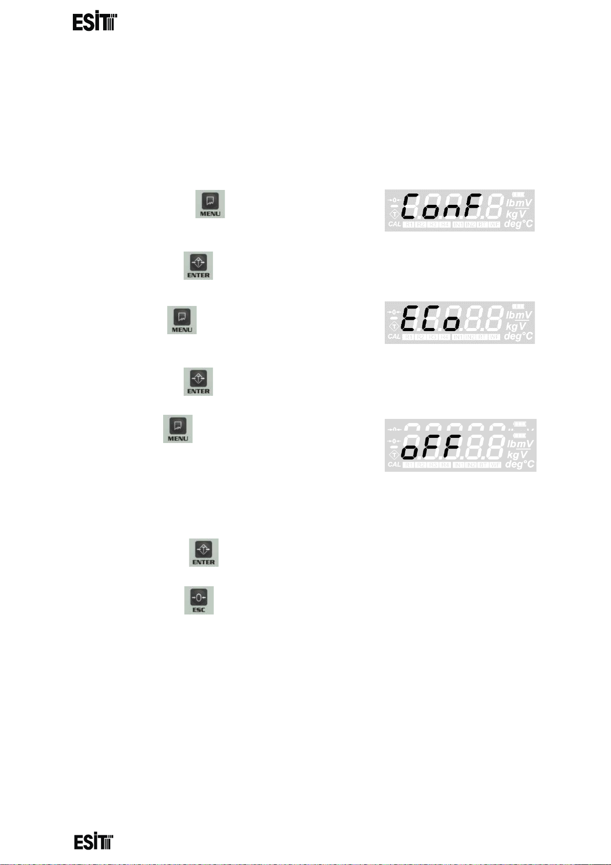
ECO MODE SETTING With this menu you can turn eco mode on or off. If the measurement value is within ±
10e range around 0 for 10 minutes while Eco mode is on, the indicator goes into eco
mode and automatically switches off the display, backlight, wifi and relays. To exit the
eco mode, either weigh a weight outside the ± 10e range of or press the buttons
other than the off key.
(1) Press key until you reach the
'Configuration Settings' menu
(2) Press the key to confirm the menu
(3) Press key until you reach the 'Eco
Mode' menu
(4) Press the key to confirm the menu
(5) Press key until reaching 'ON' for
activating and 'OFF' for deactivating the Eco Mode
(6) Press the key to save the changes.
(7) Press the key to go back to the measurement screen.
Page 18
Page 21
________________________________________________________________________________________________
SMART-2 Multi Functional Wireless Weighing Indicator User Manual
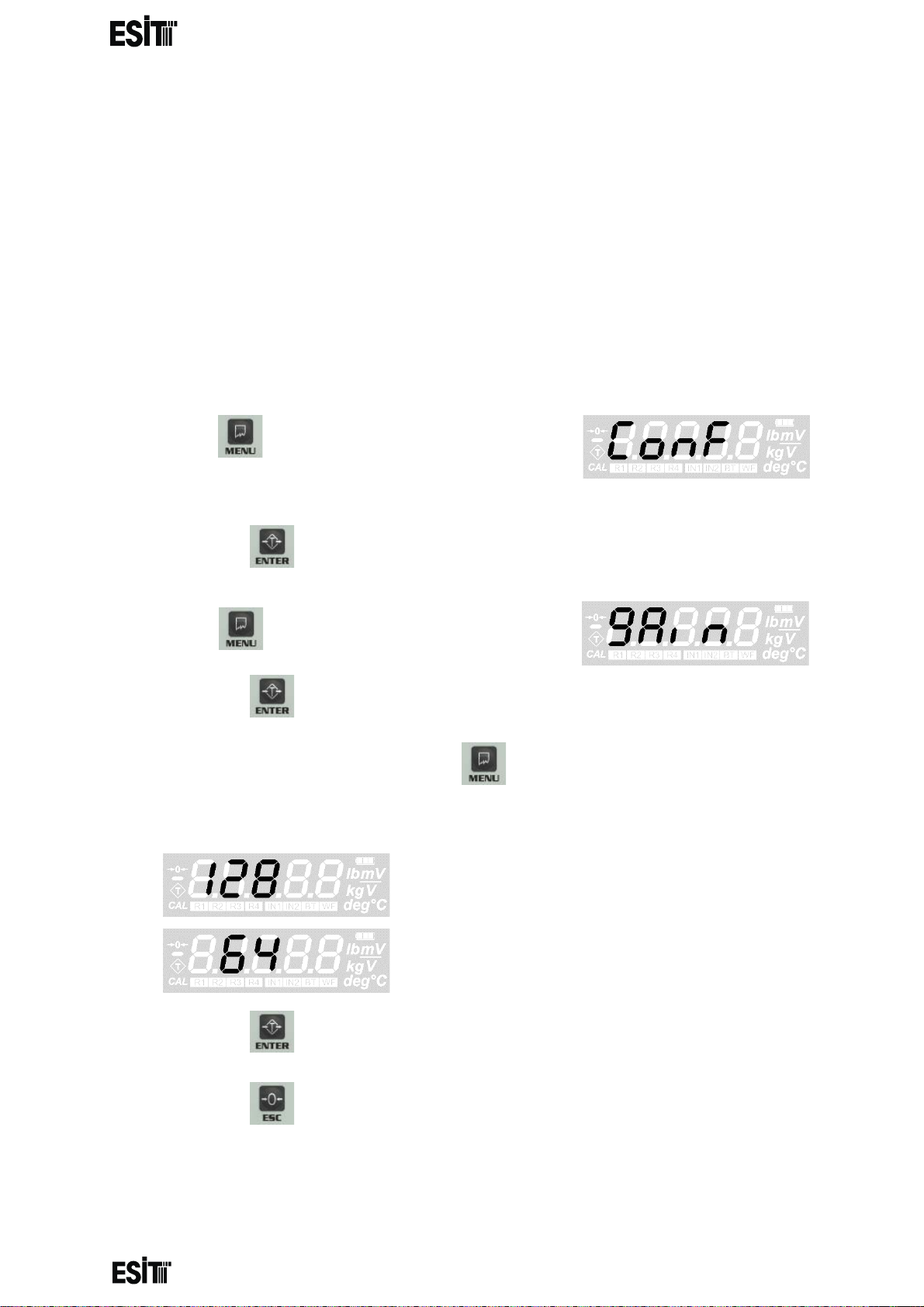
GAIN SETTING
With this value, y ou can c hoose th e int ernal upg rade v alue o f the AD C . This val ue can
be 128 or 64. 1 28 must be selected for loa d cells up to 3mV/V and 64 must be sel ected
for higher ones
(up to 6mV/V) Once the gain value has been changed, calibration must be
performed to ensure proper measurement.
WARNING: In order for thes e menu functi ons to be ac tive, the P 2 connectio n inside
the indicator must be open circuit; otherwise only recorded information will be
displayed and they are not allow ed to be chan ged. In thi s case, a speci al error cod e
will also be displayed on the indicator's screen.
(1) Press key until y ou reach the 'Configur ation
Settings' menu
(2) Press the key to confirm the menu
(3) Press key until you reach the 'Gain' menu
(4) Press the key to confirm the menu
(5) Set the gain value as you desire with menu key.
then gain 128
then gain 64
(6) Press the key to save the changes.
(7) Press the key to go back to the measurement screen.
Page 19
Page 22

________________________________________________________________________________________________
SMART-2 Multi Functional Wireless Weighing Indicator User Manual
DISPLAY BRIGHTNESS SETTING
With this value you can change the backlight brightness. Higher values consume
more energy.
(1) Press key until y ou reach the 'Configur ation
Settings' menu
(2) Press the key to confirm the menu
(3) Press key until you reach the "Display
Brightness" menu.
(4) Press the key to confirm the menu
(5) Set the display brightness as you desire with menu key.
then Maximum
then High
then Moderate
then Low
(6) Press the key to save the changes.
(7) Press the key to go back to the measurement screen.
Page 20
Page 23

________________________________________________________________________________________________
SMART-2 Multi Functional Wireless Weighing Indicator User Manual
MEASUREMENT STABILITY
When this menu option is on, any change that is les than 2e for 2 sec after the
measurement is stabile, is not displayed
(1) Press key until you reach the 'Average'
menu
(2) Press the key to confirm the menu
(3) Press key until you reach the 'TRACK'
menu
(4) Press the key to confirm the menu
(5) Set the position as you desire with menu key.
then active
then passive
(6) Press the key to save the changes.
(7) Press the key to go back to the measurement screen.
Page 21
Page 24

________________________________________________________________________________________________
SMART-2 Multi Functional Wireless Weighing Indicator User Manual
WEIGHT CALIBRATION
WARNING: In order for thes e menu functi ons to be ac tive, the P 2 connectio n inside
the indicator must be o pen c i rc ui t; otherwise an error code s pecial for this situati o n
is displayed on the indicator's screen.
ZERO CALIBRATION
(1) Press key until you reach the
'Calibration' menu
(2) Press the key to confirm the menu
(3) The 'Zero Calibration' menu flashes for a
short time and the internal count value
information starts to be displayed on the
screen. When this internal count value is
displayed, the CAL segment at the bottom left of the screen flashes
(4) After the platform is emptied, zero calibration is performed with the
key.
(5) When zero calibration is done, the indicator
automatically switches to the 'Load
calibration' menu (Load). This screen
information flashes for a short time and the
display shows the internal count value after the reset and the CAL
segment at the bottom left of the screen is lit continuously
(6) When this internal count value is displayed, the reset operation can be
performed with the key. Press the key to go back to the
normal operation (measurement) screen.
Page 22
Page 25

________________________________________________________________________________________________
SMART-2 Multi Functional Wireless Weighing Indicator User Manual
LOAD CALIBRATION
(1) Press key until you reach the
'Calibration' menu
(2) Press the key to confirm the menu
(3) The 'Load Calibration (Load)' menu flashes
for a short time and the internal count value
information starts to be displayed on the
screen. When this internal count value is
displayed, the CAL segment at the bottom left of the screen does not flash
like it does in zero calibration
(4) When this internal count value is displayed, the reset operation can be
performed with the key. When reference weight is placed on the
platform and stabi lity of the pl atform is ensur ed, key must be pressed.
NOTE: IT IS RECOMMENDED THAT THE REFERENCE WEIGHT IS AT LEAST
HALF OF THE LOADCELL CAPACITY
(5) After this operation the ten thousands digit
blinks. Numeric value of the blinking digit
can be increased with key. The place
value can be changes with key.
(6) Once the desired value is displayed on the screen, the key must be
pressed to complete the calibration and record the value.
(7) The ‘CALok’ message indicating that
the calibration is successful will appear and
the device will start to operate according to
the calibration performed in the normal
operation mode
Page 23
Page 26

________________________________________________________________________________________________
SMART-2 Multi Functional Wireless Weighing Indicator User Manual
RELAY SETTINGS
When the relay contacts are closed, the warning segments (R1 and R2) of that
relay are lit on the display.
The relays are active in '-' direction just like they are in '+' positive one.
For example; if the contacts of relay 1 is set to be closed circuit for the set value
of 1000 and above, relay contacts will also be closed for the values -1000 and
below.
Opens the menus related to relay 1
Opens the menus related to relay 2
Page 24
Page 27

________________________________________________________________________________________________
SMART-2 Multi Functional Wireless Weighing Indicator User Manual
RELAY 1 SETTINGS
RELAY 1 SET VALUE SETTING
(1) Press key until you reach the 'Relay 1'
menu
(2) Press the key to confirm the menu
(3) The first option is the ' relay 1 set value' menu.
(4) Press the key to confirm the menu
(5) The last recorded set value will be displayed
on the screen and the ten thousands digit
blinks at the same time
(6) Numeric value of the blinking digit can be increased with key. The
place value can be changes with key.
(7) Press the key to save relay 1 set value.
(8) Press the key to go back to the measurement screen.
Page 25
Page 28

________________________________________________________________________________________________
SMART-2 Multi Functional Wireless Weighing Indicator User Manual
RELAY 1 SET DIRECTION SETTING
(1) Press key until you reach the 'Relay
1' menu
(2) Press the key to confirm the menu
(3) Press key until you reach the 'Relay 1 set
direction' menu
(4) Press the key to confirm the menu
(5) The last recorded relay di rect ion w ill be
displayed on the screen
(6) Set relay 1 set direction as you desire with menu key.
then relay contacts are closed circuit
when the value
is below the set value
then relay contacts are open circuit
when the value
is above the set value
(7) Press the key to save relay 1 set direction.
(8) Press the key to go back to the measurement screen.
Page 26
Page 29

________________________________________________________________________________________________
RELAY 1 SET HYSTERESIS SETTING
SMART-2 Multi Functional Wireless Weighing Indicator User Manual
Hysteresis can be expressed as the difference between the opening and closing
values of the relay or the amount return loss.
(1) Press key until you reach the 'Relay 1'
menu
(2) Press the key to confirm the menu
(3) Press key until you reach the 'Relay 1
hysteresis' menu
(4) Press the key to confirm the menu
(5) The last recorded relay 1 hysteresis value will
be displayed on the screen and the hundreds
digit blinks at the same time
(6) Numeric value of the blinking digit can be increased with key. The
place value can be changes with key.
(7) Press the key to save relay 1 hysteresis value.
(8) Press the key to go back to the measurement screen.
NOTE: Hysteresis quantity can be between 0 and 255.
Page 27
Page 30

________________________________________________________________________________________________
SMART-2 Multi Functional Wireless Weighing Indicator User Manual
RELAY 1 DELAY TIME SETTING
A delay of up to 5 seconds can be given to set the relay. This delay period is made
with the 'delay time' menu at intervals of 0.2 seconds between 0 to 1 second and
intervals of 1 second between 1 to 5 seconds.
(1) Press key until you reach the 'Relay 1'
menu
(2) Press the key to confirm the menu
(3) Press key until you reach the 'Relay 1
delay time' setting menu
(4) Press the key to confirm the menu
(5) The recorded delay time is displayed on the screen. Set the delay time
as you desire with menu key.
then 0 second delay (without delay)
then 5 seconds delay
(6) Press the key to save the relay 1 delay time.
(7) Press the key to go back to the measurement screen.
Page 28
Page 31

________________________________________________________________________________________________
SMART-2 Multi Functional Wireless Weighing Indicator User Manual
RELAY 2 SETTINGS
(1) Press key until you reach the 'Relay 2'
menu
(2) Press the key to confirm the menu
(3) The necessary settings for 'Relay 2' are made by following the settings for
'Relay 1' (see pages 25-28).
Page 29
Page 32

Analog output
Analog output
V or mA
V or mA
Maximum DAC internal count
HVAL
LVAL
LVAL
HVAL
DMAX
Display
DMAX
Display
value
value
________________________________________________________________________________________________
SMART-2 Multi Functional Wireless Weighing Indicator User Manual
ANALOG OUTPUT (DAC) SETTINGS
ANALOG OUTPUT CALIBRATION
In order for the wei ght informatio n on the SMART-2 di splay to be use d in voltage
or current controlled automation devices, the analogue output must have been
calibrated correctly.
Calibration must b e performed after selecting t he voltage (0-5V) or current (4-20mA)
mode. See the "CONNECTIONS AND MODE SELECTIONS" section of your
manual for the selection of the analog output mode.
LVAL refers to DAC LOWEST OUTPUT VALUE
HVAL refers to DAC HIGHEST OUTPUT VALUE
DMAX refers to DAC MAXIMUM OUTPUT VALUE and
Analog output value = LVAL +
Analog output value = LVAL −
(| − | × )
(| − | × )
>
>
If set as HVAL > LVAL If set as LVAL > HVAL
NOTE: The maximum DAC internal count value can be 4095.
Page 30
Page 33

________________________________________________________________________________________________
DAC LOWEST OUTPUT VALUE (LVAL) SETTING
SMART-2 Multi Functional Wireless Weighing Indicator User Manual
It is used to determine the value to be obtained from the analogue output for
the zero value on the screen.
(1) Press key until you reach the ' DAC' men u
(2) Press the key to confirm the menu
(3) The first option is the 'DAC lowest output
(LVAL) value' menu.
(4) Press the key to confirm the menu
(5) The last recorded DAC lowest output (LVAL)
value will be displayed on the screen and the
thousands digit blinks at the same time
NOTE: WHILE CHANGING THE LVAL VALUE, THE ANALOGUE OUTPUT
VALUE FOR
FOR THAT VALUE CAN BE OBSERVED.
(6) Numeric value of the blinking digit can be increased with key. The
place value can be changes with key.
(7) Press the key to save DAC lowest output (LVAL) value.
(8) Press the key to go back to the measurement screen.
Page 31
Page 34

________________________________________________________________________________________________
SMART-2 Multi Functional Wireless Weighing Indicator User Manual
DAC HIGHEST OUTPUT VALUE (HVAL) SET TING
It is used to determine the value to be obtained from the analogue output for the DAC
maximum value (dmax) to be determined on the screen.
(1) Press key until you reach the 'D AC' menu
(2) Press the key to confirm the menu
(3) Press key until you reach the 'DAC
highest output (HVAL) value' menu "HVAL"
appears on the display.
(4) Press the key to confirm the menu
(5) The last recorded DAC highest output (HVAL)
value will be displayed on the screen and the
thousands digit blinks at the same time
NOTE: WHILE CHANGING THE HVAL VALUE, THE ANALOGUE OUTPUT
VALUE FOR
FOR THAT VALUE CAN BE OBSERVED.
(6) Numeric value of the blinking digit can be increased with
key. The place value can be changes with key.
(7) Press key to save DAC highest output (HVAL) value
(8) Press the key to go back to the measurement screen.
Page 32
Page 35

________________________________________________________________________________________________
SMART-2 Multi Functional Wireless Weighing Indicator User Manual
DAC MAXIMUM OUTPUT (DMAX) VALUE SETTI NG
This value is used to set the display value corresponding to the HVAL value.
(1) Press key until you reach the 'D AC' menu
(2) Press the key to confirm the menu
(3) Press key until you reach the 'DAC
maximum output (DMAX) value' menu "dMAX"
appears on the display.
(4) Press the key to confirm the menu
(5) The last recorded DAC maximum output
(DMAX) value will be displayed on the screen
and the ten thousands digit blinks at the same
time
(6) Numeric value of the blinking digit can be increased with key. T he
place value can be changes with key.
(7) Press the key to save DAC maximum output (DMAX) value.
(8) Press the key to go back to the measurement screen.
Page 33
Page 36

________________________________________________________________________________________________
SMART-2 Multi Functional Wireless Weighing Indicator User Manual
COMMUNICATION SETTING S
COMMUNICATION MODE SETTING
(1) Press key until you reach the
'Communication' menu
(2) Press the key to confirm the menu
(3) The first option is the 'Communication
mode' menu.
(4) Press the key to confirm the menu
(5) Set the communication mode of your choice with menu key.
NO COMMUNICATION
SENDING 4 DIGIT WEIGHT INFORMATION
CONTINUOUSLY
ADDRESSABLE COMMUNICATION
(6) Press the key to save the communication mode
(7) Press the key to go back to the measurement screen.
Page 34
Page 37

________________________________________________________________________________________________
SMART-2 Multi Functional Wireless Weighing Indicator User Manual
MOD2 communication note:
In this mode, the indicator sends the weight information after receiving the
authorization signal from its counterpart. Thus, more than one dev ic e can be
connected to the same communication line. The communication in this mode is the
same as the communication form in MOD1.
If more than one indicator is to be communicated with the com puter, the
communication mode must be s et to MOD2 and the hardware setting m ust done as
RS485.
INDICATOR ADDRESS (SCALE IDENTITY NO) SETTING
IT IS ACTIVE AND THE MENU IS AVAILABLE ONLY IF MODE 2
COMMUNICATION IS SELECTED
(1) Press key until you reach the
'Communication' menu
(2) Press the key to confirm the menu
(3) Press key until you reach the 'Indicator
address' menu
(4) Press the key to confirm the menu
(5) The last recorded indicator address will be
displayed on the screen and the hundreds digit
blinks at the same time
065 = hex41= “A”
NOTE: INDICATOR ADDRESS CAN BE ASSIGNED BETWEEN 0 AND 255
(6) Numeric value of the blinking digit can be increased with key. The
place value can be changes with key.
(7) Press the key to save the indicator address.
(8) Press the key to go back to the measurement screen.
Page 35
Page 38

________________________________________________________________________________________________
SMART-2 Multi Functional Wireless Weighing Indicator User Manual
COMMUNICATION PARITY BIT SETTING
(1) Press key until you reach the
'Communication' menu
(2) Press the key to confirm the menu
(3) Press key until you reach the
'Communication parity bit' menu
(4) Press the key to confirm the menu
(5) Set the communication parity of your choice with menu key.
then no parity bit(NO PARIT Y)
then parity bit is even (EVEN PARITY)
then parity bit is odd (ODD PARITY)
(6) Press the key to save the communication parity setting.
(7) Press the key to go back to the measurement screen.
Page 36
Page 39

________________________________________________________________________________________________
SMART-2 Multi Functional Wireless Weighing Indicator User Manual
COMMUNICATION SPEED (BAUD RATE) SETTING
The number of data bits that can be sent in one second during communication is
called the 'communication speed' (BAUD RATE). For Smart-2 indicators this
speed can be set between 1200 and 28800.
(1) Press key until you reach the
'Communication' menu
(2) Press the key to confirm the menu
(3) Press key until you reach the
'Communication speed' menu
(4) Press the key to confirm the menu
(5) Set the communication speed of your choice with menu key.
then 1200 baud communication
then 2400 baud communication
then 4800 baud communication
then 9600 baud communication
then 14400 baud communication
then 19200 baud communication
then 28800 baud communication
(6) Press the key to save the communication speed setting.
(7) Press the key to go back to the measurement screen.
Page 37
Page 40

U7.U U6. 5. 4. 3. 2. 1. 0.
7 bit
x 1 0 0 0 0 0 1
8 bit
0 1 0 0 0 0 0 1
________________________________________________________________________________________________
SMART-2 Multi Functional Wireless Weighing Indicator User Manual
COMMUNICATION DATA LENGTH SETTING
The length of the data bits to be used for communication is set by this menu. With
this parameter setting, 128 different characters can be defined in 7 bit
communication. 256 different character definition is possible only if 8 bits = 1 byte
communication is selected.
(1) Press key until you reach the 'Communication' menu
(2) Press the key to confirm the menu
(3) Press key until you reach the
'Communication data l eng t h' men u
(4) Press the key to confirm the menu
(5) Set the data length as you desire with menu key.
then 7 bit communication
then 8 bit communication
(6) Press the key to sa ve the communication data length s etting.
(7) Press the key to go back to the measurement screen.
NOTE: For example, the ASCII code equivalent of the character 'A' is 41 in the
hexadecimal (hex) system; By setting the data length, transfer is performed as
follows:
Page 38
Page 41

________________________________________________________________________________________________
SMART-2 Multi Functional Wireless Weighing Indicator User Manual
POINT-TO-POINT COMMUNICATION SETTING
Point transmission in communication occurs when 8 bit communication is selected.
The point is transmitted by setting the most meaningful bit of the digit sent as 1.
(1) Press key until you reach the
'Communication' menu
(2) Press the key to confirm the menu
(3) Press key until you reach the 'Point
transmission communication' menu
(4) Press the key to confirm the menu
(5) Set the point transmission as you desire with menu key.
NON-POINT-TO-POINT COMMUNICATION
POINT-TO-POINT COMMUNICATION
(6) Press the key to sa ve the poi nt transmission setting i n c om munication
(7) Press the key to go back to the measurement screen.
Page 39
Page 42

Display
‘+’
‘1’
‘2’ U‘3’ U‘4’ UCR
+1234
Hex 2B
31
32
33
34
0D
+123.4
‘+’
‘1’
‘2’ U‘3.’ U‘4’ UCR
Hex 2B
31
32
B3
34
0D
‘-’
‘1’
‘2.’ U‘3’ U‘4’ UCR
-12.34
Hex 2D
31
B2
33
34
0D
UCharacter
HEX
Character
HEX 0.
B0
(30+80)
5.
B5 (35+80)
1.
B1
(31+80)
6.
B6 (36+80)
2.
B2
(32+80)
7.
B7 (37+80)
3.
B3
(33+80)
8.
B8 (38+80)
4.
B4
(34+80)
9.
B9 (39+80)
(Switching on)
Addres
s
HEX
FFh
41h
________________________________________________________________________________________________
SMART-2 Multi Functional Wireless Weighing Indicator User Manual
A sample data stream (mode1, 8 bit and point-to-point communication)
U
If there is a point in the display value, hex80 is added to the ASCII value of that
digit and sent to the opposite side.
U
U
U
U
U
U
U
U
U
U
U
U
An exemplary mode2 data stream (addressed communication):
If the indicator address is set to 65 (hex41), the indicator transfers the weight
information after recei ving the following data from the opp os it e sid e.
If the address of the i ndicator i s set to 0, the w eight informati on transmissi on starts with
any character received from the serial communication line. It should be noted that the
indicator address can be between 0 and 255.
If more than one SMART-2 indicators are connected to the same communication line,
RS485 type communication must be set and a different address must be assigned to
each device.
Page 40
Page 43

________________________________________________________________________________________________
SMART-2 Multi Functional Wireless Weighing Indicator User Manual
BLUETOOTH SETTINGS
BLUETOOTH STATUS SETTING
With this menu you can turn the device's Bluetooth feature on or off.
The bluetooth module must be plugged in to the device in order to be
active.
The communication distance is 20 meters.
(1) Press key until you reach the 'BLE
settings' menu
(2) Press the key to confirm the menu
(3) The first option is the "BLE Status" menu
(4) Press the key to confirm the menu
(5) Press key until reaching 'ON' for
activating and 'OFF' for deactivating the
BLEWhen 'ON' is selected, the display will
show "Wait" message for 1-2 sec.
(6) Press the key to save the BLE status
setting.
(7) Press the key to go back to the measurement screen.
Page 41
Page 44

________________________________________________________________________________________________
SMART-2 Multi Functional Wireless Weighing Indicator User Manual
BLUETOOTH ID SETTING
With this menu, you ca n change the Bl uetooth ID of the devi ce. BLE IDs of tw o devices
in the same envir onment cannot be the same. BLE ID must be one of ASCII equi valents
of 0-9, a-z, A-Z characters.
(1) Press key until you reach the 'BLE
settings' menu
(2) Press the key to confirm the menu
(3) Press key until you reach the 'Change
BLE ID' menu
(4) Press the key to confirm the menu
(5) The last recorded BLE ID will be displayed on
the screen and the hundreds digit blinks at the
same time
065 = hex41= “A”
NOTE: BLE ID can be as signe d between 0 and 255 and can be selected only
between 0-9, a-z and A-Z character range
(6) Numeric value of the blinking digit can be increased with key. The
place value can be changes with key.
(7) Press the key to save the BLE ID. "wait" appears on the display.
(8) Press the key to go back to the measurement screen.
NOTE: See page 55 for Bl uetooth connectivity from the An dr oi d app l i cati on .
Page 42
Page 45

________________________________________________________________________________________________
SMART-2 Multi Functional Wireless Weighing Indicator User Manual
WIFI SETTINGS
WIFI STATUS SETTING
With this menu you can turn the device WiFi feature on or off.
The wifi module must be plugged in to the device in order to be active.
The communication distance is 40 meters.
(1) Press key until you reach the 'WiFi
settings' menu
(2) Press the key to confirm the menu
(3) The first option is the 'WIFI Status' menu.
(4) Press the key to confirm the menu
(5) Press key until reaching 'ON' for
activating and 'OFF' for deactivating the WIFI.
When 'ON' is selected, the display will show
"Wait" message for 1-2 sec.
(6) Press the key to save the WIFI status setting.
(7) Press the key to go back to the measurement screen.
Page 43
Page 46

________________________________________________________________________________________________
SMART-2 Multi Functional Wireless Weighing Indicator User Manual
WIFI MODE SETTING
With this menu, you can change WiFi mode of the device as Access Point or Station.
One of the devices in the same environment must be in the Access Point, and the
others must be in Station mode. Since the station devices will be connected to the
access point device, first the settings of the access point device must be made and
WiFi feature must be turned on.
(1) Press key until you reach the 'WiFi
settings' menu
(2) Press the key to confirm the menu
(3) Press key until you reach the ' WIFI mo de'
menu
(4) Press the key to confirm the menu
(5) Press key until 'AP' is displayed for the
Access Point mode and 'STA' for the Station
mode. The "wait" appears on the display when
either mode is selected.
(6) Press the key to save the WIFI mode setting.
(7) Press the key to go back to the measurement screen.
Page 44
Page 47

________________________________________________________________________________________________
SMART-2 Multi Functional Wireless Weighing Indicator User Manual
WIFI Access Point ID SETTING
This menu is active only when device mode is AP.
With this menu, you can change the WIFI Access Point ID of the device. WIFI AP ID
must be one of ASCII equivalents of 0-9, a-z, A-Z characters.
(1) Press key until you reach the 'WiFi
settings' menu
(2) Press the key to confirm the menu
(3) Press key until you reach the 'Change
WIFI AP ID' menu
(4) Press the key to confirm the menu
(5) The last recorded WIFI AP ID will be displayed
on the screen and the hundreds digit blinks at
the same time
065 = hex41= “A”
NOTE: WIFI AP ID can be assigned between 0 and 255 and can be selected only
between 0-9, a-z and A-Z character range
(6) Numeric value of the blinking digit can be increased with key. The
place value can be changes with key.
(7) Press the key to save the WIFI AP ID.
(8) Press the key to go back to the measurement screen.
Page 45
Page 48

________________________________________________________________________________________________
SMART-2 Multi Functional Wireless Weighing Indicator User Manual
WIFI Station ID SETTING
This menu is active only when device mode is STA.
With this menu, y ou c a n c h ang e the WIFI Stat ion I D of the devi ce. This ID must matc h
with the APID of the WiFi device in AP mode in the same environment. WIFI STA ID
must be one of ASCII equivalents of 0-9, a-z, A-Z characters.
(1) Press key until you reach the 'WiFi
settings' menu
(2) Press the key to confirm the menu
(3) Press key until you reach the 'Change
WIFI STA ID' menu
(4) Press the key to confirm the menu
(5) The last recorded WIFI STA ID will be
displayed on the screen and the hundr eds
digit blinks at the same time
065 = hex41= “A”
NOTE: WIFI STA ID can be assigned between 0 and 255 and can be selected
only between 0-9, a-z and A-Z character range
(6) Numeric value of the blinking digit can be increased with key. The
place value can be changes with key.
(7) Press the key to save the WIFI STA ID.
(8) Press the key to go back to the measurement screen.
Page 46
Page 49

________________________________________________________________________________________________
SMART-2 Multi Functional Wireless Weighing Indicator User Manual
WIFI Name SETTING
With this menu you can change WiFi Name of the device. Each device on the same
network should be g i v en a different name si nce the WiFi name will appear as a dev i c e
name in the applicati o n. WIFI Name must be one o f ASC II eq ui v al ents o f 0-9, a-z, A-Z
characters.
(1) Press key until you reach the 'WiFi
settings' menu
(2) Press the key to confirm the menu
(3) Press key until you reach the 'Change
WIFI Name' menu
(4) Press the key to confirm the menu
(5) The last recorded WIFI Name will be displayed
on the screen and the hundreds digit blinks at
the same time
065 = hex41= “A”
NOTE: WIFI Name can be assigned between 0 and 255 and can be selected only
between 0-9, a-z and A-Z character range
(6) Numeric value of the blinking digit can be increased with key. The
place value can be changes with key.
(7) Press the key to save the WiFi name.
(8) Press the key to go back to the measurement screen.
NOTE: See page 53 for Wi-Fi connection from the Android app. See page
59 to connect the devices to your own Wifi network.
Page 47
Page 50

________________________________________________________________________________________________
SMART-2 Multi Functional Wireless Weighing Indicator User Manual
TEMPERATURE CALIBRATION SET TINGS
With this menu you can change temperature calibration of the device. The device has
5-point temperature compensation feature. When calibrating the temperature, the
load cell must be empty.
There are five ranges in temperature compensation: (, -5 °C) , (-5 °C, 10 °C), (10 °C,
30 °C), (30 °C, 50 °C), (50 °C,). The ranges that cannot be set with this menu are
ignored during compensation. So if 3 v alues are se t, 3 point t emperatur e compensati on
is done. This compensation works partial linearly.
WARNING: In order for these menu functions to be active, the P2 connection inside
the indicator must be open circuit; otherwise an error code special for this situation is
displayed on the indicator's screen. IT IS RECOMMENDED NOT TO USE THESE
SETTINGS IF YOU DO NOT HAVE SUITABLE DEVICES
(1) Press key until you reach the
'Temperature Calibration Settings' menu
(2) Press the key to confirm the menu
(3) The display shows the current temperature
value and the number of range covering the
temperature for 2 seconds
(4) Real time internal ADC count value deviation
will appear on the display .
(6) Press the key to save the temperature calibration setting.
(7) "TCLok" wi ll appear s h owing that the calibration
is successful.
(8) Press the key to go back to the measurement screen.
Page 48
Page 51

________________________________________________________________________________________________
SMART-2 Multi Functional Wireless Weighing Indicator User Manual
RESTORING FACTORY SETTING S
With this menu, you can restore the device to factory settings. The values that require
the calibration jumper to be installed will not be changed.
(1) Press key until you reach the 'Reset'
menu
(2) Press the key to confirm the menu
(3) Press the key until 'Yes' appears in order
to to restore the factory settings
(4) Press key to restore factory settings
Page 49
Page 52

________________________________________________________________________________________________
SMART-2 Multi Functional Wireless Weighing Indicator User Manual
PERFORMING TARING WITH TARE key
When inactivity is ensured manual taring is performed by
pressing key. When taring is completed, the display
is reset and net warning segment is lit. Upon loading, tare
becomes visible.
In order to cancel the tare, the inactivity must be provided and
the button must be pressed. The net warning segment
goes out when tare is cancell ed.
ZEROING DISPLAY VALUE WITH ZERO key
When the inactivity is ensured and if the weight value on
the screen is less than MAX / 10, the weight value can be
zeroed with the key
The display is zero when key is pressed and actual
zero symbol is displayed on the screen.
Page 50
Page 53

________________________________________________________________________________________________
SMART-2 Multi Functional Wireless Weighing Indicator User Manual
CONNECTIONS AND MODE SELECTIONS
CALIBRATION SWITCH (P2)
The calibration switch P2 must be switched on to change and calibrate the
display settings of the device.
The display setti ngs c a n be ac ces sed a nd s aved v al ues c an b e dis play ed w hile
P2 is shorted but the chang es made c annot be sav ed and t he error code ' Err50'
is displayed on the screen.
The calibration menu cannot be accessed while P2 is closed circuit and the
error code 'Err50' is displayed on the screen
Page 51
Page 54

1 2 3 4 5 6 7 8 9
10
11
12
13
14
15
16
17
18
19
20
21
-LC 1 input
+LC 1 input
-LCFeed +LCFeed
LCGround
0V GND
+V (6-24V)
-Io +Io
+Vo
GND
DI2
DI1
RL 2/1
RL 2/1
RL 1/1
RL 1/2 RS485VCC
Rx / B Tx / A RS485GND
1 2 3 4 5 6 7 8 9
10
11
12
13
14
15
16
17
18
19
20
21
-LC 1 input
+LC 1 input
-LCFeed +LCFeed
LCGround
0V GND
+V (6-24V)
-Io +Io
+Vo
GND
DI2
DI1
RL 2/1
RL 2/2
RL 1/1
RL 1/2 RS485VCC
Rx / B Tx / A RS485GND
________________________________________________________________________________________________
SMART-2 Multi Functional Wireless Weighing Indicator User Manual
ANALOG OUTPUT mode selection
0-5V analog output connection
In the printed circuit of the indicator, the connections are as follows provided
that the leftmost terminal slot is number 1.
V
4-20mA analog output connection
In the printed circuit of the indicator, the connections are as follows provided
that the leftmost terminal slot is number 1.
WARNING: Changes to the card (short-circuit, open circuit and
interfering with components) other than those lis ted above may cause permanent
damage to the indicator and incorrect operation of the device and are not covered by the
warranty.
Page 52
Page 55

________________________________________________________________________________________________
SMART-2 Multi Functional Wireless Weighing Indicator User Manual
ANDROID APPLICATION SETTING S
Settings that can be made via Smart can also be done via the android application.
Device settings can be made via following application is wireless connection
Bluetooth/WiFi is used.
CONNECTION WITH WIFI MODULE
First, open the Smart's WiFi by following the "WIFI STATUS SETTING" section.
Make sure that "WIFI MODE SETTING" is "AP" (see "WIFI TYPE SETTING" section
for this).
Scan your WIFI networks from your Android phone and connect to the "loadcellx"
network by ty pi ng "Esit.s mart2" to password field.
Once connected, open the "Smart2" android application and click the "WIFI" button.
”ALERT You are already connected to loadcellA. Do you want to use that loadcell” ,
“No” , “Yes” appears on the screen. Please perform opera t ion s tep 4 w hen
proceeded with “Yes” and step 1 when proceeded with “No”
Page 53
Page 56

________________________________________________________________________________________________
SMART-2 Multi Functional Wireless Weighing Indicator User Manual
1-Click on the "+" shown in the figure
2-The location service must be turned on after proceed with "Yes" to message
displayed.
3-Select the smart you want to connect to in the opened page.
4-You can see the instant weight information on the smart screen by clicking on the
"GET" button on the pop-up screen. By clicking on the "SETTINGS" button, you can
make the settings you need.
Page 54
Page 57

________________________________________________________________________________________________
SMART-2 Multi Functional Wireless Weighing Indicator User Manual
CONNECTION WITH BLUETOOTH MODULE
(1) After turning on your Android device's Bluetooth, open the Smart2 application
and click the BLUETOOTH button.
(2) Click on the "Connect" button.
(3) Select the Smart you want to communicate with.
Page 55
Page 58

________________________________________________________________________________________________
SMART-2 Multi Functional Wireless Weighing Indicator User Manual
(4) The weight value can be obtained when the "GET" button is clicked on the
pop-up screen. When the "Ref" button is clicked, the weight value is
automatically updated.
(5) More than one smarts can communicate simultaneously via Bluetooth. Click
the "+" button for this. It must be noted that “BLUETOOTH IDs” of the Smart
devices are different. BLUETOOTH IDs can be set from "Change BLE ID"
menu.
When 1 indicator is active When 2 indicators
are active
Page 56
Page 59

________________________________________________________________________________________________
SMART-2 Multi Functional Wireless Weighing Indicator User Manual
(6) By clicking "SETTINGS" button, desired changes can be made.
MAKING DEVICE SETTINGS
Display Settings
"Decimal Point", "Step", "Capacity" and "Unit" settings can be changed as desired.
After changing, press "SAVE" button at the end of the page.
Page 57
Page 60

________________________________________________________________________________________________
Configuration Settings
SMART-2 Multi Functional Wireless Weighing Indicator User Manual
Make the desired configuration settings and press "SAVE" button.
Relay Settings
Make the desired relay settings and press "SAVE" button.
Analog Output (DAC) Settings
Make the desired analog output settings and press "SAVE" button.
Page 58
Page 61

________________________________________________________________________________________________
Communication Settings
SMART-2 Multi Functional Wireless Weighing Indicator User Manual
Make the desired communication settings and press "SAVE" button.
Wifi Connection Setting
If Wifi connection modules are used and it is intended to read weight data from many
smart devices through a local network, the follow ing procedure should be followed for
each smart device.
NOTE: This setting only applies to smart devices with the WIFI module installed. Not
suitable for use with BLUETOOTH devices.
(This setting is made if it is intended to connect to a local network and receive data
simultaneously from many smart devices.)
(1) First make sure that the "wifi mode setting" of the smart is AP.
(2) Click the "WIFI" button in the WiFi settings section of the Android application.
(3) rite the "SSID" and "Pass" in the figure to SSID and password fields of the
network from which you would like to get weight data and click "SAVE" button.
Page 59
Page 62

________________________________________________________________________________________________
SMART-2 Multi Functional Wireless Weighing Indicator User Manual
(4) Change Smart "wifi mode setting" as "STA".
(5) When the "WAIT" message disappears from the Smart screen, connection to
the local network is done.
(6) If you cannot connect to the local network, an error ERR.09 will be displayed
on the smart screen. In this case check the necessary connections and repeat
the procedure.
(7) When the Smart is taken to "STA" mode, the "IP" submenu will appear under
the WIFI menu. You can check your smart's IP address from this section.
(8) The desktop application "Smart2 reader" can be used to access the weight
information sent by the Smarts connected to the local network.
(9) After opening the application, the IP address of the Smart that is intended to
get data from must be written to the tex t box under the indicators.
(10) Then click the "Start" button to see the weights of the respective Smart
or Smart devices.
(11) The source code for the desktop program is available on the CD
included in the product package. For further information, please contact us.
Page 60
Page 63

________________________________________________________________________________________________
Calibration Setting
SMART-2 Multi Functional Wireless Weighing Indicator User Manual
It is possible to perform calibration through both Smart and application.
(1) Press the "CALIBRATION" button
(2) If there is no load on the system, press "GET" button.
Page 61
Page 64

________________________________________________________________________________________________
SMART-2 Multi Functional Wireless Weighing Indicator User Manual
(3) Press the "ZERO" button
(4) Place the weight you want to calibrate in the system and press "Get" button.
Repeat the process several times and press the "LOAD" button after seeing
that the value is stable.
(5) Enter the weight value you want to calibrate in the system to the "Load Value"
section and press "Get" butt o n.
Page 62
Page 65

________________________________________________________________________________________________
SMART-2 Multi Functional Wireless Weighing Indicator User Manual
Temp Calibration Setting
Settings made via Smart are visible.
(1) Press the "CALIBRATION" button
(2) Press the "GET" button
(3) Press the "SAVE" button
Page 63
Page 66

These errors indicate that the device needs to be reset or repaired
Error99
No response from ADC
Error98,97
ADC serial communication is incorrect
Error96
Bluetooth reset error
Error95
Bluetooth sleep mode error
Error94
Bluetooth name change error
Error93
Wifi APID change error
Error92
EEPROM Writing error
Error91
EEPROM full error
These Errors Can Be Fixed After The Operation Is Repeated
Error1
Weight data is above maximum value
Error2
The weight data is below the minimum value
Error3
The weight data is too large to be reset
Error4
ESC key is stuck
Error4
Menu key is stuck
Error6
Enter key is stuck
Error7
Wifi / BLE name entered incorrectly
Error8
Changing name when wifi is connected
Error9
Wifi name change error
Error10
EEPROM consumed 5% of its life
Error19
Calibration value cannot be 0
Error50
Calibration jumper inserted
0Error51
mV and V values cannot be calibrated
Error52
mV and V values cannot be reset
IP address error. The device is in STA mode but is not connected to
any network.
________________________________________________________________________________________________
SMART-2 Multi Functional Wireless Weighing Indicator User Manual
ERROR CODES
The following error codes can be displayed on SMART-2 indicators during
measurement and as a result of incorrect setting. These error codes and their causes
are listed below
Error60
Page 64
Page 67

A T F W Nisantepe Mh. Gelin Cicegi Sk. No:36 Cekmekoy 34794 İstanbul (216) 585 1818 (216) 585 1819 www.esit.com.tr
Smart-2 User Manual - R00
 Loading...