

ESi Ergo VICTORY 2VT-C36-30 Series, VICTORY 2VT-C48-24 Series, VICTORY 2VT-C48-30 Series, VICTORY 2VT-C36-24 Series Instructions Manual
ASSEMBLY AND OPERATION
VICTORY
2 LEG ELECTRIC TABLE BASE
Model 2VT-C36-24-___
Model 2VT-C36-30-___
Model 2VT-C48-24-___
Model 2VT-C48-30-___
2VT Rev A 1/17
___ = SLV, BLK or WHT

VICTORY 2 LEG ELECTRIC TABLE BASE PARTS AND TOOLS
PARTS PROVIDED
Work
Surface
PLEASE REVIEW these instructions before beginning the assembly procedures. Check that all the parts shown
below were provided with your order. Contact your supplier if any materials are missing. Do not discard the
packaging until satised that the product operates to your satisfaction.
Cross Channels (2)Legs with Motor (2)
Feet (2)
Digital Keypad (1)Control Unit (1) Power Cable (1)Motor Cables (2)
Top Supports (2)
Foot Plates (2)
Cable Clamps and Ties Fasteners
(6)
(6)(3)
M8x12 (12)
CAUTION: Hand-tighten screws only. Do not use
ADDITIONAL TOOLS REQUIRED
power tools.
• 5mm Allen key
• Phillips screwdriver
CAUTION: Always check that screws
used to attach components to the
work surface are not too long for the
thickness of the surface.
M6x35 (8)
ST 4.8x19 (19) ST 2.9x19 (2)
2
ASSEMBLY VICTORY 2 LEG ELECTRIC TABLE BASE
Rear
Front
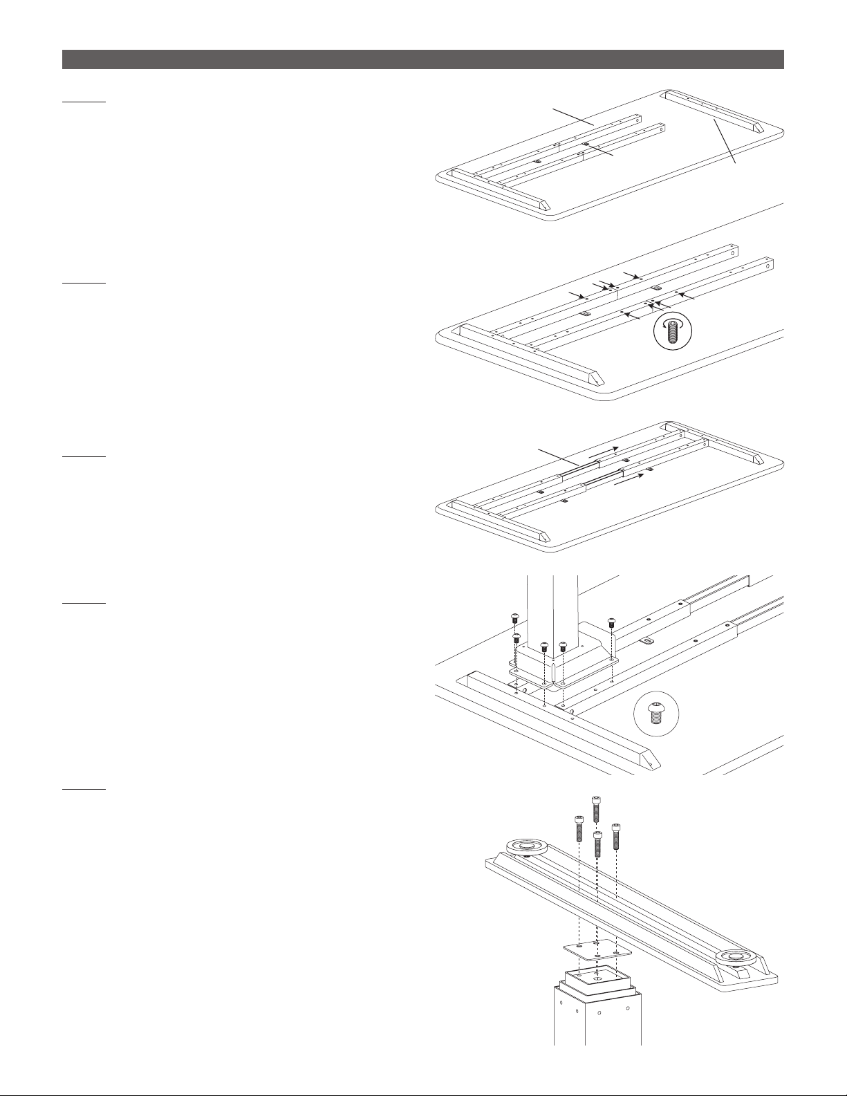
STEP 1
With the table top facing down on a soft, clean
surface, arrange the cross channels and top
supports as shown.
• Positioning does not need to be exact at this time.
• Mounting tabs on the cross channels face inward,
toward each other.
• Holes on the top supports are offset to the rear.
STEP 2
Use an 5mm Allen key to loosen the M10 set screws
on the cross channels (two on each side of center).
STEP 3
Adjust the cross channels to their approximate nal
lengths, as shown.
• Center the inner piece in each cross channel.
Cross Channel
Mounting Tab
Top
Support
Loosen
Set Screws
Center
Inner Piece
STEP 4
Attach the side legs to the cross channels and top
supports with six M8x12 screws per leg.
• Use a 5mm Allen key.
• Two screws attach to each cross channel and
two screws attach to the top supports.
STEP 5
Attach a foot plate and foot to each of the side
legs with the M6x35 screws.
• First, place the foot plate onto the leg with the
smooth side up.
• Position the foot over the foot plate, as shown.
The short side of each foot should face the rear.
• Screw the foot securely in position using a 5mm
Allen key.
M8x12
M6x35
Foot Plate
Side
Legs
3
 Loading...