

Page 1

Ultra Mobile Guitar & Microphone
24-bit / 192 kHz USB Audio Adapter
User’s Guide
Page 2

ESI - Copyright © 2019
Revision 1, December 2019
www.esi-audio.com
Page 3

ESI UGM192
INDEX
1. Introduction .................................................................................................................................. 4
1.1 Features ................................................................................................................................................................ 4
2. Installation .................................................................................................................................... 6
2.1 System Recommendation ..................................................................................................................................... 6
2.2 Hardware Installation ........................................................................................................................................... 6
2.3 Driver & Software Installation ............................................................................................................................. 6
2.3.1 Installation under Windows .............................................................................................................................. 7
2.3.2 Installation under OS X / macOS ...................................................................................................................... 9
3. Windows Control Panel ............................................................................................................. 10
3.1 Latency and buffer settings ................................................................................................................................ 11
3.2 DirectWIRE and virtual channels ...................................................................................................................... 11
3.3 Windows Audio Settings ................................................................................................................................... 13
4. OS X / macOS Control Panel .................................................................................................... 14
4.1 Latency and buffer settings ................................................................................................................................ 14
5. Specifications .............................................................................................................................. 15
6. General Information .................................................................................................................. 16
3
Page 4
ESI UGM192
1. Introduction
UGM192, an ultra mobile guitar and microphone to USB-C audio interface with excellent 24-bit /
192kHz / 114dB quality, allows you to connect an electric guitar via its Hi-Z instrument input and a
professional dynamic or condenser microphone to your PC or Mac or to many compatible mobile
devices such as smart phones and tablet computers that support USB audio. The backside offers a
stereo output that you can use for playback and for real time input monitoring, i.e. with headphones.
This makes UGM192 the perfect companion for guitar and professional microphone recording
applications on the road or in your studio. You can use it to jam with a guitar and microphone, process
the signal in real time and listen to the mix directly via headphones - no special additional devices are
needed: you simply plug UGM192 between your guitar, headphones, the microphone and your
computer or mobile device.
UGM192 is a USB-C device, optimized for USB 3.1 operation. It is also compatible with standard
USB 2.0 ports.
1.1 Features
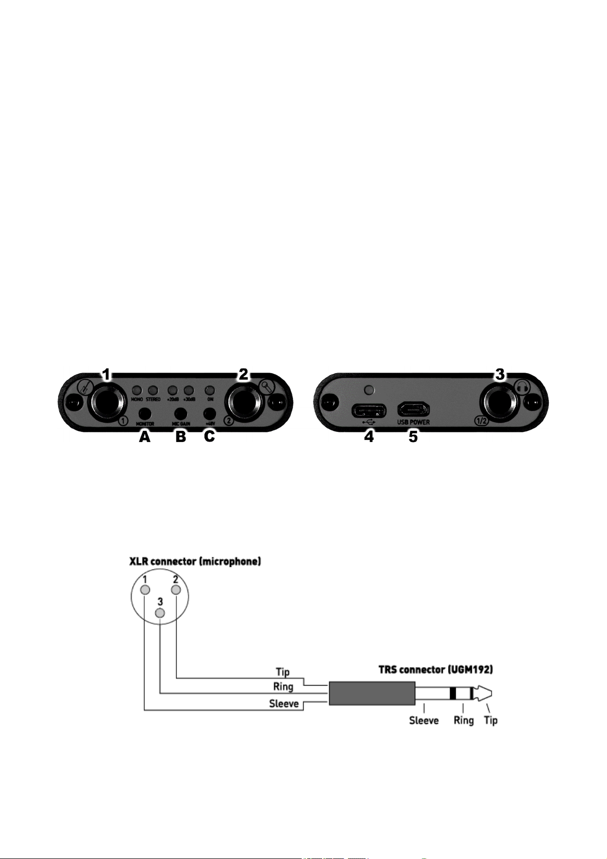
The front and back panel of the UGM192 hardware has these main features:
1. Hi-Z instrument input channel 1 with unbalanced 1/4" TS connector. Use this connector to
connect an electric guitar or similar instrument.
2. microphone input channel 2 with balanced 1/4" TRS connector. Use this connector to connect
a dynamic or condenser microphone. If you need to make an adapter cable from 1/4" TRS to the
XLR connector of your microphone, you need to use the following wiring diagram for it:
Please note that you need to have a balanced 1/4"TRS connector (= as it would be "stereo") when
assembling such a cable.
4
Page 5

ESI UGM192
3. headphone and line output with unbalanced stereo 1/4" TRS connector. Use this connector to
connect professional studio headphones or to connect the unit to the input of active studio
monitors, a monitor controller or a mixing desk.
4. USB-C connector to connect the device to a computer or mobile device. Use this connector to
connect the unit to your Mac or PC or to a mobile device by using one of the two included USBC connection cables. When the device is working, the power LED over the USB-C connector
will be on.
5. microUSB power connector to supply the unit with additional power. While the unit is fully
bus powered and does not need an additional power supply normally, it can be needed in some
cases to provide extra additional power (for instance when connecting it to a mobile phone with
limited battery life). In such a case, you can use this port to supply the unit with power from a
portable battery pack or from a USB power supply. Note that you cannot use this connector to
record / playback audio signals via your PC or Mac. You need to use the USB-C port instead.
A. Monitor switch, with this button you can control the real time hardware input monitoring of the
device. There are three different settings and you can step through them by pushing the button
several times:
1. If you push it once, the MONO LED will be turned on and you will be able to monitor the
input channel 1 signal on the left output channel and the input channel 2 signal on the right
output channel.
2. If you push it twice, the STEREO LED will be turned on and you will be able to monitor the
input channel 1 and input channel 2 signals each on both left and right output channels.
3. If you push it three times, the monitoring will be turned off again and both LEDs will be off.
In this case, you cannot hear the input channel signals on the output.
B. Mic Gain switch, with this button you can control the input gain of the microphone input channel
2:
1. If you push it once, the +20dB LED will be turned on and the input level will be increased by
20dB in volume.
2. If you push it twice, the +30dB LED will be turned on and the input level will be increased
by 30dB in volume.
3. If you push it three times, the LEDs will be turned off and the additional volume gain is
disabled.
C. +48V phantom power switch, with this button you can enable or disable the +48V phantom
power that is needed if you want to use input channel 2 with a condenser microphone. When the
phantom power is enabled, the ON LED will be turned on. When it is disabled, it will be turned
off.
Note: Only turn on the phantom power after you have connected your microphone. Avoid doing this
before you connect it.
Note: Before you unplug any cable, it is strongly recommended to disable the phantom power.
5
Page 6

ESI UGM192
2. Installation
2.1 System Recommendation
UGM192 is not simply a standard digital audio interface, but a high-resolution device capable of
advanced processing of audio content. Even though UGM192 is built to have low-CPU resource
dependability, system specifications play a key part in the UGM192s performance. Systems with
more advanced components are generally recommended.
Minimum System Requirements
PC
-
Windows 7 / 8 / 8.1 or 10 (32- and 64-bit) operating system
-
1 available USB 2.0 or USB 3.1 port ("type A" or "type C")
Mac
-
OS X / macOS 10.9 or higher
-
1 available USB 2.0 or USB 3.1 port ("type A" or "type C")
2.2 Hardware Installation
UGM192 is directly connected to an available USB port of your computer. The connection to your
computer is done either via a so-called "type A" or a "type C" port. For each connection type, a
separate cable is included in the package. Connect one end of that cable with UGM192 and the other
one to the USB port of your computer.
USB "type A" port of a computer USB "type C" port of a computer
2.3 Driver & Software Installation
After the connection of UGM192, the operating system automatically detects it as a new hardware
device. However, you should install our driver to use it with full functionality.
We strongly recommend to download the latest driver from www.esi-audio.com before installing
UGM192 on your computer. Only if our driver software is installed, all the functionality is provided
under Windows / OS X / macOS.
You can always find the latest drivers and software for both PC and Mac for your UGM192 by
going to this page in your web browser:
>>> http://en.esi.ms/111 <<<
6
Page 7

ESI UGM192
2.3.1 Installation under Windows
The following text explains how to install UGM192 under Windows 10. If you use Windows 7,
Windows 8 or Windows 8.1, the steps are basically the same. Do not connect UGM192 to your
computer before you install the driver – if you have connected it already, disconnect the cable for
now.
To start the installation, launch the setup program, which is an .exe file that is inside a recent driver
download from our website by double clicking on it. When launching the installer, Windows might
display a security message. Make sure to allow the installation. After that, the following dialog on
the left will appear. Click Next and then the dialog on the right will appear:
Now click Install. Files are now being copied. After some time an additional dialog will appear:
Confirm this by clicking Next. Again some files are being copied and in some cases you will be
prompted with a Windows Security message like this:
7
Page 8

ESI UGM192
Confirm it by clicking Install. After a while the installation then will be completed and the following
dialog will appear:
Once you see the window on the left, click Finish. In many cases, the window on the right appears
then. We strongly suggest to select Yes, restart the computer now and then click Finish.
You can connect UGM192 to your computer anytime now. Windows will automatically setup the
system so you can use the device.
To confirm the completion of the installation after rebooting the system, please check if the orange
color ESI icon is displayed in the taskbar notification area as shown below.
If you can see it, the driver installation has been completed successfully.
8
Page 9

ESI UGM192
2.3.2 Installation under OS X / macOS
To use UGM192 under OS X / macOS, you need to install the control panel software from the
download from our website. This procedure is basically the same for all the different versions of OS
X / macOS.
The control panel gets installed by double clicking on the .dmg file and then you will get the following
window in Finder:
To install the UGM192 panel, click and drag it with your mouse to the left to Applications. This will
install it into your Applications folder.
Controlling some of the basic options of UGM192 under OS X / macOS can be done via the Audio
MIDI Setup utility from Apple (from the folder Applications > Utilities), however the main functions
are controlled by our dedicated control panel application that has now been placed into your
Applications folder.
9
Page 10

ESI UGM192
3. Windows Control Panel
This chapter describes the UGM192 Control Panel and its functions under Windows. To open the
control panel double click on the orange ESI icon in the task notification area. The following dialog
will appear:
The File menu provides an option called Always on Top that makes sure the Control Panel stays
visible even when working in other software and you can launch the Windows Audio Settings there.
The Config menu allows you to load the Factory Defaults for the panel and driver parameters and the
Help > About entry shows current version information. Under the File, Config, DirectWIRE and Help
menu items, you can find the following main functions and sections:
INPUT
This section contains signal level meters for the two physical input channels.
OUTPUT
This section contains volume control sliders and signal level meters for the two playback channels.
Under it there is button that allows you to MUTE playback and there are playback level values
displayed for each channel in dB.
To control both left and right channels simultaneously (stereo), you need to move the mouse pointer
in the middle between the two faders. Click directly on each fader to change channels independently.
SAMPLERATE
This section shows the currently selected sample rate which you can also change (as long as no audio
is being played back or recorded) by clicking on it. As UGM192 is a digital audio interface, all
applications and audio data will be processed with the same sample rate at a given time. The hardware
natively supports rates between 44.1 kHz and 192 kHz.
10
Page 11

ESI UGM192
3.1 Latency and buffer settings
Via Config > Latency in the Control Panel it is possible to change the latency setting (also called
“buffer size”) for the driver of UGM192. A smaller latency is the result of a smaller buffer size and
value. Depending on the typical application (e.g. for playback of software synthesizers) a smaller
buffer with a smaller latency is an advantage. At the same time, the best latency setting indirectly
depends on the performance of your system and when the system load is high (for instance with more
active channels and plugins), it can be better to increase the latency. The latency buffer size is selected
in a value called samples and if you are curious about the actually latency time in milliseconds, many
recording applications display this value inside the settings dialog there. Please note that the latency
has to be setup before launching the audio application using UGM192.
Via Config > USB Buffer, you can select the number of USB data transfer buffers used by the driver.
In many cases, these values do not need to be changed, however as they have a bit of an influence on
the audio latency and on stability, we allow you to fine tune this setting. In some applications where
real time processing and latency values or better performance at high system load are critical, you
can optimize the values here additionally. Which value is best on your system depends on a number
of factors such as what other USB devices are used at the same time and what USB controller is
installed inside your PC.
3.2 DirectWIRE and virtual channels
Under Windows, UGM192 has a feature called DirectWIRE that allows fully digital internal loopback
recording of audio streams. This is a great feature to transfer audio signals between audio applications,
create mix downs or to provide content for online live streaming applications.
Note: DirectWIRE is a very powerful feature for special applications and professional usage. For
most standard recording applications with only one audio software and for pure audio playback, no
DirectWIRE settings are needed at all and you should not change those settings unless you know
what you want to achieve.
To open the related settings dialog, click on the DirectWIRE entry in the top menu of the control
panel software and the following window appears:
This dialog allows you to virtually connect playback (output) channels and input channels with virtual
cables on the screen.
11
Page 12

ESI UGM192
The three main columns are labeled INPUT (the physical hardware input channel), WDM/MME (the
playback/output and input signals from audio software that use the Microsoft MME and WDM driver
standard) and ASIO (the playback/output and input signals from audio software that uses the ASIO
driver standard).
The rows from top to down represent the available channels, first the two physical channels 1 and 2
and under it two pairs of VIRTUAL channels numbered 3 to 6. Both the physical and virtual channels
are represented as separate stereo WDM/MME devices under Windows and in your applications and
also as channels accessible via the ASIO driver in software that uses that driver standard.
The two buttons MIX 3/4 TO 1/2 and MIX 5/6 TO 1/2 at the bottom allow you to mix the audio signal
that is played via virtual channels 3/4 (or virtual channels 5/6) to the physical output 1/2, if required.
Finally, the MME/WDM and ASIO playback can be muted (= not sent to the physical output) by
clicking on OUT if required.
DirectWIRE example
For further explanation, let’s look at the following example configuration. Please note that every
application of DirectWIRE is specific and there is hardly any universal setup for certain complex
requirements. This example is simply to illustrate some of the powerful options:
You can see here connections between ASIO OUT 1 and ASIO OUT 2 to WDM/MME VIRTUAL IN
1 and WDM/MME VIRTUAL IN 2. This means that any playback of an ASIO application via channel
1 and 2 (for instance your DAW) will be sent to the WDM/MME wave device 3/4, allowing you to
record or maybe live stream the output of the ASIO software with an application that records on
channel 3/4.
You can also see that the playback of channel 1 and 2 (WDM/MME OUT 1 and WDM/MME OUT 2)
is connected with the ASIO input of channel 1 and 2 (ASIO IN 1 and ASIO IN 2). This means that
anything any MME/WDM compatible software plays on channel 1 and 2 can be recorded / processed
as input signal in your ASIO application. This signal cannot be heard via the physical output of
UGM192 since the OUT button is set to mute.
Finally, the enabled MIX 3/4 TO 1/2 button means that everything played via virtual channel 3/4 can
be heard on the physical output of UGM192.
12
Page 13

ESI UGM192
3.3 Windows Audio Settings
Via the Windows Sound control panel icon or by selecting File > Windows Audio Settings in our
control panel software, you can open these Playback and Recording dialogs:
In the Playback section you can see the main MME / WDM audio device, which Windows labels
Speakers. This represents the output channels 1 and 2. In addition there are two devices with virtual
channels, UGM192 VCH34 and UGM192 VCH56.
In order to hear the system sounds and to hear sounds from standard applications such as your web
browser or a media player via UGM192, you need to select it as the default device in your operating
system by clicking on it and then click Set Default.
The Recording section similarly has the main input device that represents channel 1 and 2 which are
used to record signals from the physical input channels. There are also two devices with virtual
channels, UGM192 VCH34 and UGM192 VCH56.
Please note that any audio hardware that is installed in your computer already will also appear on this
list and you need to choose which one you want to use by default here. Note that most audio
applications have their own settings for this.
13
Page 14

ESI UGM192
4. OS X / macOS Control Panel
This chapter describes the UGM192 Control Panel and its functions on the Mac. Under OS X /
macOS, you can find an UGM192 icon in the Applications folder. Double click on this to launch the
control panel software and the following dialog will appear:
The File menu provides an option called Always on Top that makes sure the Control Panel stays
visible even when working in other software and you can launch the macOS Audio Settings there.
The Config menu allows you to load the Factory Defaults for the panel parameters and the Help >
About entry shows current version information. The main dialog has two sections:
OUTPUT
This section contains volume control sliders and signal level meters for the two playback channels.
Under it there is button that allows you to MUTE playback and there are playback level values
displayed for each channel in dB.
To control both left and right channels simultaneously (stereo), you need to move the mouse pointer
in the middle between the two faders. Click directly on each fader to change channels independently.
SAMPLERATE
This section shows the currently selected sample rate which you can also change (as long as no audio
is being played back or recorded) by clicking on it. As UGM192 is a digital audio interface, all
applications and audio data will be processed with the same sample rate at a given time. The hardware
natively supports rates between 44.1 kHz and 192 kHz.
4.1 Latency and buffer settings
Unlike under Windows, on OS X / macOS, the latency setting is depending on the audio application
(i.e. DAW) and usually setup there inside the audio settings of that software and not in our control
panel software. If you are unsure, check the manual of the audio software you are using.
14
Page 15

ESI UGM192
5. Specifications
- USB 3.1 audio interface with USB-C connector ("type C" to "type C" cable included)
- USB 2.0 compatible ("type A" to "type C" cable included)
- USB bus powered
- separate power connector for optional mobile power supply (microUSB cable required, not
included)
- professional microphone preamp:
- balanced 1/4" TRS connector
- 48V phantom power support
- -8.6dBu max. input level
- +10dB / +20dB gain options
- 2.2kOhm input impedance
- professional Hi-Z instrument input:
- unbalanced 1/4" TS connector
- -8.4dBu max. input level
- 500kOhm input impedance
- 24-bit / 192kHz AD converter:
- 114dB dynamic range A-weighted
- THD+N -100dB (@ -1dBFS)
- line / headphone output:
- 1/4" stereo TRS connector
- max. output level +6.4dBu (@ 0dBFS)
- THD+N 0.0024% A-weighted (@ fs=48kHz)
- 32~600ohm impedance
- 24-bit / 192kHz DA converter:
- 114dB dynamic range A-weighted
- THD+N -100dB (@ 0dBFS)
- supports Windows 7 / 8 / 8.1 / 10 with ASIO 2.0, MME, WDM and DirectSound
- DirectWIRE support under Windows with virtual audio channels for internal loopback recording
- supports OS X / macOS (10.9 and above) via the native CoreAudio USB audio driver from
Apple (no driver installation needed)
- 100% class compliant (no driver installation required on many modern operating systems such as
Linux via ALSA as well as iOS based and other mobile devices)
15
Page 16

ESI UGM192
6. General Information
Trademarks
ESI and UGM192 are trademarks of ESI Audiotechnik GmbH. Windows is a trademark of Microsoft
Corporation. Other product and brand names are trademarks or registered trademarks of their
respective companies.
The FCC and CE Regulation Warning
This device complies with Part 15 of the FCC Rules. Operation is subject to the following two
conditions: (1) this device may not cause harmful interference, and (2) this device must accept any
interference received, including interference that may cause undesired operation. Caution: Any
changes or modifications in construction of this device with are not expressly approved by the party
responsible for compliance, could void the user's authority to operate equipment.
Note: This equipment has been tested and found to comply with the limits for a Class A digital device,
pursuant to Part 15 of the FCC Rules. These limits are designed to provide reasonable protection
against harmful interference when the equipment is operated in a commercial environment. This
equipment generates, uses, and can radiate radio frequency energy and, if not installed and used in
accordance with the instruction manual, may cause harmful interference to radio communications.
Operation of this equipment in a residential area is likely to cause harmful interference in which case
the user will be required to correct the interference at his own expense. If necessary, consult an
experienced radio/television technician for additional suggestions.
Correspondence
For technical support inquiries, contact your nearest dealer, local distributor or ESI support online at
www.esi-audio.com. Please also check our extensive Knowledge Base with Frequently Asked
Questions, installation videos and technical details about our products in the support section of our
website.
Disclaimer
All features and specifications subject to change without notice.
Parts of this manual are continually being updated. Please check our web site www.esi-audio.com
occasionally for the most recent update information.
16
 Loading...