

Page 1

WARRANTY
EGO SYStems Inc. warrants the return policy to its original purchaser as follows; All EGO
SYS products, under normal use, will be free from faulty as long as the purchaser owns this
product.
The terms of warranty is 15 months to EGO SYS distributors considering a 3-month temporary
stock period ahead of being sold to the end user. Therefore, the actual terms of warranty is 12
months to the end user.
EGO SYS will, at its sole option, repair or replace a product, which is found to be defective. This
warranty shall be null and void if, in the sole opinion of EGO SYS, a product failure is the result of
misuse, abuse, modification, or misapplication. Except as expressly provided above, EGO SYS
products are provided 'as is' without any kind of warranty. No claim is made for merchantability or
fitness for any purpose. In no event will EGO SYS be liable for any direct, indirect, consequential, or
incidental damages arising out of use of the product. The purchaser must contact EGO SYS or its
regional representative to receive prior approval before returning a faulty unit. All such returns must
be shipped to EGO SYS' headquarters in Seoul, Korea as being packaged in the original or equivalent
protective packaging material (Rack, PCI card, Power Cables, connection cables), with freight
prepaid and adequate insurance.
If the returned product is deemed to be defective, the repaired or replacement product will be
back to you at no extra charge via the carrier chosen by EGO SYS.
TRADEMARKS
ESI, Waveterminal U24 and U24 are trademarks of EGO SYStems Inc. IBM is a registered trademark
of International Business Machines Corporation. Windows is a trademark of Microsoft Corporation.
Apple, Macintosh and Power Macintosh are trademarks of Apple Computer, Inc. Other product and
brand names are trademarks or registered trademarks of their respective companies.
RADIO FREQUENCY INTERFERENCE
NOTE: This equipment has been tested and found to comply with the limits for a Class A device,
pursuant to Part 15 of the FCC Rules, and EN50 081-1/2:1992 of CE Test Specifications. This
equipment generates, uses, and can radiate radio frequency energy. If not installed and used in
accordance with the instruction, it may cause interference to radio communications.
CORRESPONDENCE
For technical support inquiries, contact your nearest Waveterminal U24 dealer or contact us directly.
Direct all other correspondence to:
EGO SYStems Inc.
Suite 1003, Shinhan Bldg. 45-11 Yoido-dong
Youngdungpo-gu, Seoul, Korea
Tel: +82 2 780-4451~3 Fax: +82 2 780-4454
Web Site: www.egosys.net
E-mail: webmaster@egosys.net
Second Edition July. 2002
* All features and specifications subject to change without notice.
1
Page 2

CONTENTS
1. Overview______________________________________________ 3
2. Features ______________________________________________ 4
3. System Requirement ____________________________________ 5
4. Hardware Installation ___________________________________ 6
5. External Connections ___________________________________ 8
6. Driver Installation in PC________________________________ 12
1) XP ________________________________________________ 12
2) 98SE, ME, 2000 _____________________________________ 24
3) Launching MME Control Panel________________________ 29
4) Launching ASIO2.0 Control panel _____________________ 30
5) Control Panel Reference. MME & ASIO ________________ 31
7. Driver Installation in MAC ______________________________ 39
1) Apple Sound Manager and ASIO2.0 ____________________ 39
2) MAC Control Panel Reference_________________________ 41
8. Using U24 in PC
________________________________________ 49
1)Working with Applications -MME ______________________ 49
2) Working with Applications -ASIO2.0 ___________________ 52
9. Using U24 in MAC
______________________________________ 55
1) Working with Applications____________________________ 55
SPECIFICATIONS ______________________________________ 59
2
Page 3

1. Overview
Thank you for choosing ESI Waveterminal U24, an USB digital audio
interface.
Waveterminal U24 (U24) is an USB digital audio interface with 24-bit
A/D, D/A for Apple Macintosh computers and IBM PC compatible
system. U24 can be used with your digital audio recording software to
record and playback simultaneously (full duplex) through stereo analog
or stereo digital audio sources with exceptional audio quality.
USB stands for Universal Serial Bus, which means it connects
peripherals to a computer. It is an evolved form of old serial or parallel
bus.
USB makes installation of new peripherals much simpler, just plug and
play. You don’t have to open the PC to add a peripheral any more, just
plug and turn it on. With USB-compliant computers and peripherals,
there are no more worries about IRQ setting, DIP switch setting, or
card installation. Even the computer turned on, it is no problem with
attaching and removing devices. Just plug and play!
Practically, there is no limit on number of devices that can be linked to
the computer using USB hubs.
USB even provide electrical power and supplies it, which eliminates
messy power cables from working space.
If you are a professional or in need of a professional quality USB audio
interface, you have made a sound investment in Waveterminal U24.
3
Page 4

2. Features
24-bit Analog-to-Digital and Digital-to-Analog Converters
Highest quality 24-bit AD/DA converters in U24 provide unmatched
sound quality with exceptionally low noise.
2-In/2-Out Analog Audio Inputs and Outputs and Headphone connector
U24 provides 1/4” phone jacks for use with –10dBV nominal level
consumer audio equipment. Unlike some audio cards that deliberately
boost their output levels to give you a false sense of audio quality, U24
gives you a true indication of your levels. Nothing’s added or taken
away unless you intend to do so. If you need to adjust levels, digital
level adjustment is provided for analog inputs and outputs. You can
also use Analog Out L as Headphone connector.
S/PDIF Coaxial /Optical Digital In & Out
U24 offers S/PDIF digital input and output via Optical or Coaxial ports.
There’s no additional conversion process for signal already recorded.
Multiple Sample Rate Support
Supports all denomination of 44.1kHz or 48kHz standard sample rates
from 32kHz, 44.1kHz and 48kHz. U24 can be used in a variety of
applications.
Real-time Hardware Sample Rate Conversion
Regardless of the type of sample rates, U24 automatically converts the
incoming digital audio signal to the sample rate of your choice in realtime.
4
Page 5

Functions as an independent Signal Converter
When Digital In Clock Source is selected, U24 can be operated as an
independent signal converter. In this mode, U24 is completely
disconnected with the computer, but it will send out any incoming
signal to both analog and digital output ports.
ASIO2.0 and MME driver support
You can use U24 with ASIO2.0 applications such as a Cubase, Nuendo
and also MME applications such as Cakewalk, Samplitude.
3. System Requirement
Most of all, your system has to have at least one available USB port to
use U24.
PC
1. Intel Pentium II 400 MHz CPU or equivalent AMD CPU
2. Windows 98SE/ME/2000/XP operating system
3. 1 open USB port
4. 128MB RAM
5. Digital audio recording/playback software
MAC
1. Power Macintosh G3 or higher
2. Mac OS 9.0 to 9.2.x
3. One available USB port
4. “USB Device Extension” version 1.4.1 or later is needed
5. 128MB of RAM
(Highly depends on the system requirements of your audio software)
5
Page 6

4. Hardware Installation
Before you begin, make sure you have read your computer’s manual on
installing USB devices. Your computer’s manual should describe the
precautions you should take.
Shutting down computer wouldn’t need for installing an USB device to
the computer. However, we will take it from the start to make sure you
can follow every detail of installation.
1. Find the USB port on your computer. USB port is looked
like below. You can find it by the PS/2 or serial ports on
the back of desktop computer system.
USB port on computer
2. Plug in appropriate plug of USB cable (called Series A
plug) to the USB port of computer. You will notice that
USB ports on computer and U24 are different.
Series A plug
3. Connect the other end of the USB cable (Series B plug) to
the USB port of U24.
Series B plug
6
Page 7

4. Turn on the computer. You will see “PWR” LED on U24
lights in red. U24 get the power from the computer via
USB cable so you don’t need to attach any external power
supplier.
Series A Plug is used for those devices on which the
external cable is permanently attached like Mouse, Keyboard
and USB hub etc…
Series B Plug is for that requires detachable external cables
and used for devices like Printers, Scanners, Modems, Stand
Alone Hubs.
Parts of this manual are continually being updated. Please
check our web site http://www.egosys.net occasionally for
the most recent update information.
7
Page 8
5. External Connections
U24 has many features that can enhance your audio production
environment. If you are serious enough to about your digital audio, you
may want to take time to read through this section carefully. While you
may not need all of these features, and simply opt to plug in the cables
to get started right away, you should at least be aware of U24’s
capabilities – in case you need them later on.
BASIC CONNECTIONS
In a typical audio production studio or workstation, where you have
both digital and analog devices, this set up treats your PC or Macintosh
as a stereo master recorder. In this case, monitoring of U24 will be
similar to “through-the-tape” monitoring, where you monitor your
input and output sources from the tape recorder’s point.
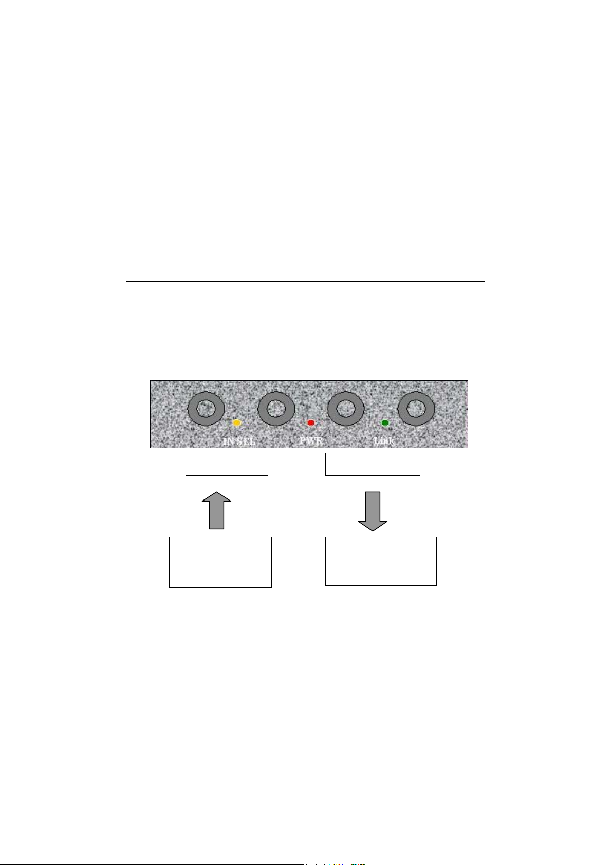
L -Analog In - L -Analog Out -R
Front panel of U24
IN SEL
From the stereo
output of an external
analog audio device
To the monitor system
or stereo input of
mixer
If you plan to use U24 in a digital mastering environment, you may
choose to connect analog outputs of U24 directly to your power
amplifier’s inputs instead of sending it through the console/mixer.
8
Page 9

TIP: Analog Out L can be used as Headphone connector.
Coaxial Out / Coaxial In Optical Out / Optical In USB plug In
Rear panel of U24
Digital Input of
external digital
devices CD, MD,
DAT
Digital Output of
external digital
devices CD, MD,
DAT
9
Page 10
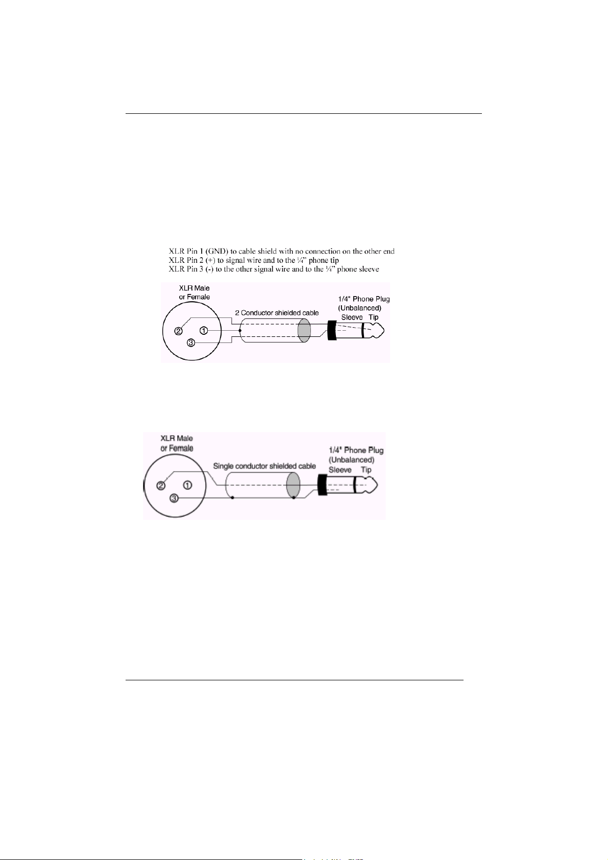
CABLES & ADAPTERS
Let’s talk about the cables and connectors those can be used with U24.
Analog connector
U24 uses 1/4” phone connectors for analog input/output connectors.
The wiring method for unbalanced connections with XLR connectors to
¼” phone connectors (tip and sleeve only) using shielded twisted pair
cable (2 wire + shield) is as follows:
The wiring method for unbalanced connections with XLR connectors to
unbalanced ¼” phone connectors (tip and sleeve only) using coaxial
cable (1 wire + shield) is as follows:
10
Page 11

Digital connector
1. Coaxial connector
S/PDIF (IEC-958) uses 75ohm Coaxial cable and RCA connectors.
U24 uses RCA connector that is the same cable as used in video
transmission. Shown below is conventional RCA connector and you
can use this for transmitting/receiving S/PDIF digital audio data
from/to U24.
2. Optical connector
Optical version of S/PDIF interface, which is usually, called Toslink,
because it uses Toslink optical components. The transmission media is
1mm plastic fiber and the signals are transmitted using visible LED light.
The optical signals have exactly same format as the electrical S/PDIF
signal, they are just converted to light signals.
11
Page 12
6. Driver Installation in PC
1) XP
If the hardware installation was done properly, your computer will look for
the Windows native drivers need to use U24 and start to install them.
After Windows native driver was done properly, you must keep going to
next exclusive U24 driver.
1. Insert the provided Driver CD or diskette into the CD-Rom drive or
floppy disk drive and (or unzip U24 file and) copy all the files to a
folder at your hard disk. Name it whatever you like. Do not move or
delete any of these files, not even after the installation. Run “setup”
icon. After that, if you see below message, simply click “Yes”
12
Page 13

2. Check ‘I accept the agreement’ and click “Install”.
13
Page 14
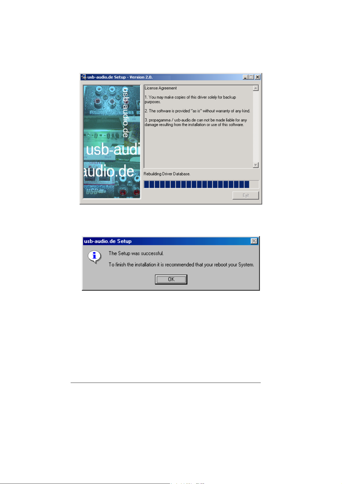
3. Exclusive U24 driver will be installed.
4. Click “Reboot now”
14
Page 15

5. After install the software, Go to Device Manager again.
It looks nothing changed. However, your Windows now recognized
U24 exclusive driver.
15
Page 16
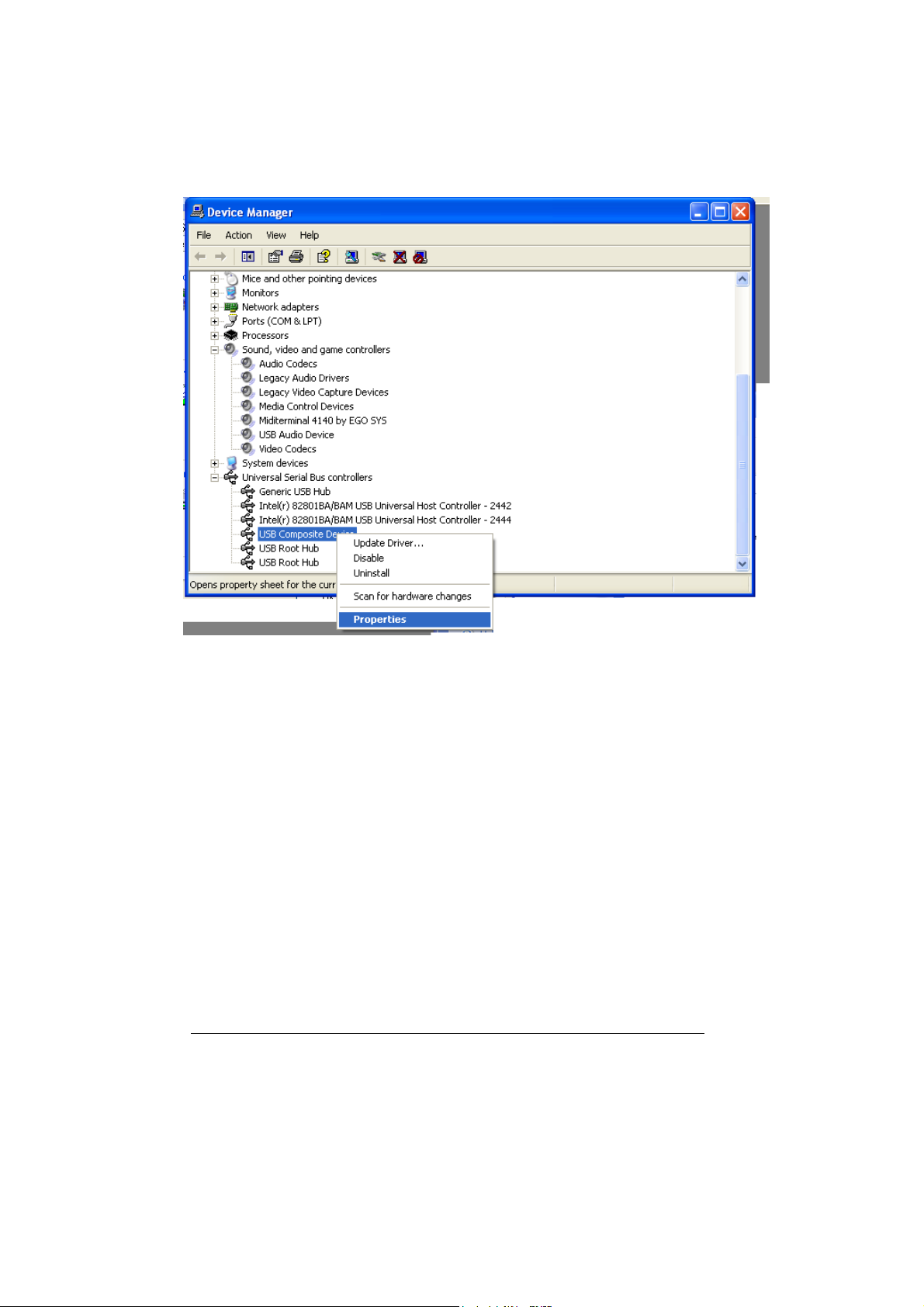
6. Right mouse click and click Properties.
16
Page 17
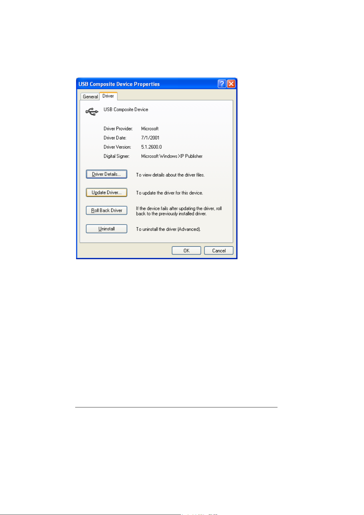
7. Click “update Driver”.
17
Page 18
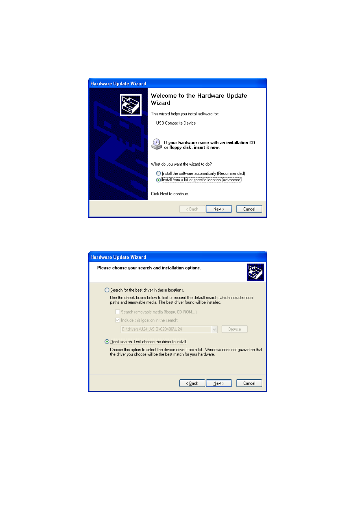
8. Choose “Install from a list or specific locations”.
9. Choose “Don’t search. I will choose the driver to install”.
18
Page 19

10. Choose ‘Waveterminal U24’
19
Page 20

20
Page 21

21
Page 22

22
Page 23

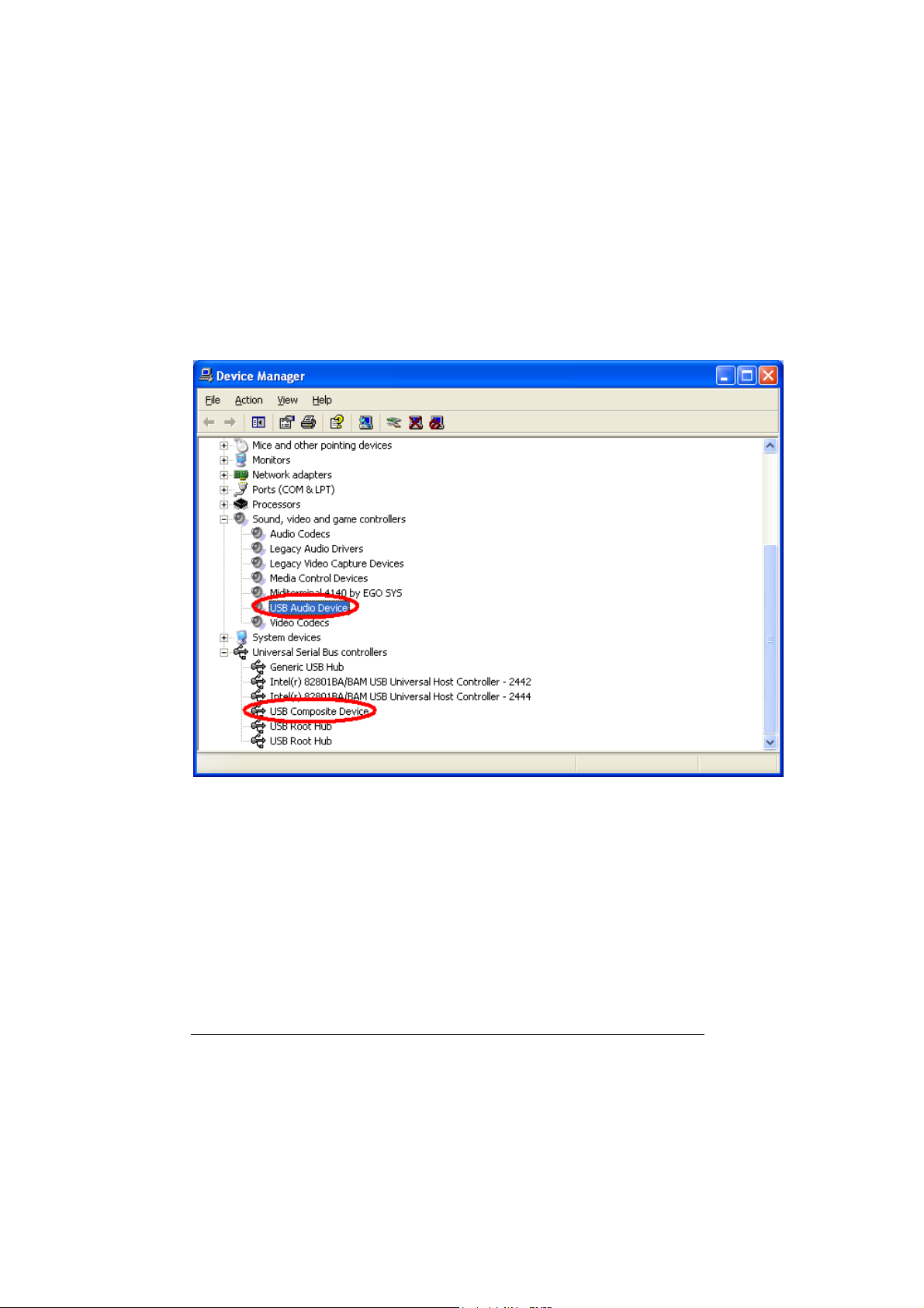
11. After rebooting your computer, open your system’s Device
Manager and confirms that “Waveterminal U24” is shown
under “Universal Serial Bus Controllers.” Now you’re ready to
use ASIO driver software and also MME softwares with
control panel.
23
Page 24

2) 98SE, ME, 2000
When you install U24 driver in next step, ‘USB device’ will be
disappeared.
1. Insert the provided Driver CD or diskette into the CD-Rom
drive or floppy disk drive and copy all the files to a folder at
your hard disk. Name it whatever you like. Do not move or
delete any of these files, not even after the installation. Run
“setup” icon.
After that, if you see below message, simply click “Yes”
24
Page 25

2. Check ‘I accept the agreement’ and click “Install”.
3. Now, U24 driver will be installed.
25
Page 26

4. Click “Reboot now”
5. In order to complete the installation and reboot again.
26
Page 27

27
Page 28

6. After rebooting your computer, open your system’s Device
Manager and confirm that “Waveterminal U24” is shown under
“Universal Serial Bus Controllers”.
28
Page 29

3) Launching MME Control Panel
After exclusive U24 driver was done properly, click ‘U2xpanel.exe’.
'U2xpan.exe' will be appeared.
* Caution: Even Two U24 control panel looks different, they have
same functions and its same name. See page 33 for MME control
panel functions.
29
Page 30

4) Launching ASIO2.0 Control panel
CUBASE VST
After launching Cubase, Go to ‘Option’ -> ‘Audio Setup’ -> System.
Select ‘‘Waveterminal U2A/U24 ASIO driver’ for the ASIO Device.
30
Page 31

5) Control Panel Reference. MME & ASIO
This control panel is pretty simple.
However you should be careful with ‘System performance’ in Dithering
menu.
In the case of U24, You have to choose the bit-rate of your recordings
in ‘Recording resolution’.
If your music file is 24bit recording and you're going to play it back via
U24's 16bit, you can use dithering to increase quality.
Also, you can choose different system performance depends on your
computer’s efficiency.
Choosing ‘Highspeed’ and ‘Faster’ will bring fast processing.
But if your computer has low efficiency and you select ‘Highspeed’, it
cause noise problem. We generally recommend to you to select ‘Normal
+MME’ or ‘normal’.
31
Page 32

32
Page 33

Caution: Even Two U24 control panel looks different, they have same
functions and its same name.
INPUT/OUTPUT LEVEL FADERS
1. Level Faders
Click and drag to change the input and output levels. U24 is fixed
to use –10dBV input/output reference level. Check the manuals of
the audio equipment you want to connect to U24’s inputs. It should
be –10dBV device. The numbers on the bottom show the relative
levels in dB. When you place mouse cursor over the level fader,
fader will light in blue and mouse cursor changed to cross arrow
figure. You can use wheel mouse or click the fader and drag to
adjust the value of I/O level.
2. GANG MODE
Links the L-R faders for stereo operation. Un-select the Gang
Mode if you need to control the left and right levels independently.
USB WAVE IN SELECT
Select the input source type for audio recording.
1. ANALOG IN
Selects the analog input port (-10dBV unbalanced) on the U24 as
the USB wave input source.
2. DIGITAL IN
Selects the digital input port (SPDI/F Coaxial or Optical) on the
U24 as the USB wave input source.
DIGITAL IN SELECT
Select the input connector type for your digital audio input.
33
Page 34

1. COAXIAL
Selects the Coaxial input port (RCA type S/PDIF format) on the
U24 as the digital input source.
2. OPTICAL
Selects the Optical input port (Tos-link, S/PDIF format) on the U24
as the digital input source.
CLOCK SOURCE
Clock Source determines that U24 will reference to. Clock Source is the
time reference that determines precisely where each digital audio sample
begins and ends. Also, Clock Source in U24 control panel gives unique
function to the unit by selecting between two different sources.
1. INTERNAL
Selects U24’s on-board clock source as the reference. This is the
default mode for recording analog/digital audio through U24. Use
this mode if you are recording audio signal, playing back audio file
or using Real-time Sampling Rate Converter.
2. DIGITAL IN
Selects the digital audio input’s data as the clock source. Selecting
this mode causes U24 functions as an independent operation status
from computer. As you can see below, USB WAVE IN SELECT
section is disappeared and USB WAVE OUT of
ANALOG/DIGITAL OUT MIXER section is disabled.
In this mode, you can operate U24 as a signal converter, but U24 is
now completely separate from the computer. That means you
cannot record any input source to the computer and play any audio
source from the computer. However, any incoming audio signal
(either analog or digital) can be sent out through three different
output ports. Analog audio signal can be converted to digital audio
data, digital audio data would be converted to analog audio signal
and even digital audio data can be transferred to different connector
type.
34
Page 35

ANALOG OUT MIXER
This is where you select the source that is routed to the Analog Output
jacks of U24. You can select either Analog In or Digital In for input
monitoring. USB WAVE OUT can be selected simultaneously with one of
the input source monitoring.
1. ANALOG IN
Signal connected to Analog Input ports of U24 is routed to the
Analog Output ports for input monitoring.
2. DIGITAL IN
Signal connected to Digital Input port of U24 is routed to the
Analog Output ports for input monitoring.
3. USB WAVE OUT
Output of wave device selected to USB Audio Device is routed to
the Analog Output ports for monitoring.
DIGITAL OUT MIXER
This is where you select the source that is routed to the Digital Output
jacks (Coaxial and Optical) of U24.
1. ANALOG IN
Signal connected to Analog Input ports of U24 is routed to the
Digital Output ports for input monitoring
.
2. DIGITAL IN
Signal connected to Digital Input port of U24 is routed to the
Digital Output port for input monitoring
35
.
Page 36

3. USB WAVE OUT
Output of wave device selected to USB Audio Device is routed to
the Digital Output port for monitoring.
MIX MODE
When more than one output source is selected to be played back
simultaneously in the Analog or Digital Out Mixer, you are actually
combining the data of two digital audio signals together, resulting in an
overall gain of about 6dB/bit for each signal combined. This can cause the
output circuit to overload and create a noticeable click or distortions as the
combined level can exceed 0 dB peak level. Mix Mode gives you the
choice as to how such excessive levels are handled by U24.
1. DYNAMIC
The combined signal levels are not adjusted by U24. In this mode
clipping signals are audible, but left untouched. If you want to
adjust the levels, you can do so by adjusting the levels from the
audio software or by manually reducing the output level faders of
U24.
2. SOFT
The combined signal levels are reduced automatically by U24,
depending on the number of signal sources combined. For two
combined signals, the output signal is reduced by –6 dB.
If output-monitoring sources don’t contain peak level (0 dB peak)
programs, combining them probably would not cause any clipping or
distortion. In such cases, you may opt for the Dynamic mode, as it will
allow you to add the signals for a much ‘hotter’ output. On the other hand,
if your sources already contain peak level programs, you may need to
select the Soft mode or manually adjust the levels of each output source
you have selected.
36
Page 37

SAMPLE RATE
Sample rate determines the number of samples per second that is used to
convert analog audio to digital audio.
As most of you may know, sample rate for CD-DA is 44.1kHz and
professional digital audio masters are usually recorded at 48kHz sample
rate. U24 may be used to sample analog audio at 48kHz, but at some point
in time it must be converted down to 44.1kHz for it to be used in a viable
consumer format, such as CD-DA. Once you convert (dither) the data
down to a lower sample rate format, you will experience some losses in
frequency response. However, analog audio recorded with higher sample
rate and bit resolution will sound cleaner and retain more accurate
frequency response when they are dithered down to lower bit rate or
converted to lower sample rate.
1. AUTO
Sample rate is automatically set by the selection you make in your
digital audio recording software during analog audio recording or
by the encoded signal format during digital audio recording.
2. SAMPLE RATE
There are three different sample rates available – 32kHz, 44.1kHz
and 48kHz. If you want to convert sample rate in real time, you
can select desired sampling rate among them.
REAL-TIME SAMPLE RATE CONVERTER
U24 can function as a real-time sample rate converter. This is U24’s
unique function that you cannot find from any other digital audio interface.
You can change the incoming digital signal to a different sample rate by
choosing Internal word clock and selecting a desired sample rate. The
maximum conversion ratio is 3:1, so if your input signal’s sample rate is
96kHz, you can convert it down to 32kHz (96/3) or convert 11kHz signal
up to 32kHz (11x 3). Real Time Sample Rate Converting functions only
for incoming digital signal. Connect digital source to Coaxial/Optical
Input port and choose desired sampling rate. Now the sampling rate of the
signal you can get from digital output port is converted.
37
Page 38

However, you cannot change the sampling rate of .wav file that playback
through the application. If you try to convert it, it only sounds like
sampling up (faster speed than normal) or sampling down (slower than
normal).
DIGITAL OUT (IEC 958) TYPE
Digital Out Type selector determines the type of data format to be used on
the digital output jack of U24.
1. CONSUMER (IEC 958 Type II)
Generally known as S/PDIF (Sony Phillips Digital Interface), select
this mode if you are sending digital audio output from U24 to a
S/PDIF equipped audio device.
2. PROFESSIONAL (IEC 958 Type I)
Generally known as AES/EBU, select this mode if you are sending
digital audio output from U24 to an AES/EBU audio device.
Important Notice: Since the adaptation of IEC958 no longer
distinguishes between S/PDIF and AES/EBU, some of the older
AES/EBU audio equipment requires a higher signal level than
U24’s digital output levels (which conform to IEC 958 standards).
38
Page 39

7. Driver Installation in MAC
1) Apple Sound Manager and ASIO2.0
U24 works best when using it with ASIO compatible audio software.
However, you can also use it as a default Sound Manager device instead of
built-in device in your Macintosh computer.
There are different driver installation procedures for these two cases.
APPLE SOUND MANAGER DEVICE
For the system sound monitoring, CD monitoring, and running ASIOincompatible application, you don’t need to install or add any special driver
or file. The moment you connect the U24 to the USB port on the MAC,
you can use U24 instantly. However, as we mentioned in system
requirements part, you must have “USB Device Extension” version 1.4.1
or later to use U24.
Only thing you have to do is to make a copy of the “U24 Control Panel” in
a convenient place (such as Apple Menu) in your hard disk. You will use
this to change the settings of U24.
ASIO DRIVER
To use ASIO driver with U24, you need to do two things as follows:
1. Locate the “U24” file in the CD-ROM, and drag it into the
“Extensions” folder in the System Folder in your startup disk. Or
39
Page 40

simply you can drag it into the System Folder, and the system will
puts the file into the right place for you. You need to restart your
Macintosh.
2. Locate the “EgoSys Waveterminal U24” file in the CD-ROM, and
drag it into the “ASIO Drivers” folder of your desired application
(PEAK, Logic Audio, for example).
40
Page 41

2) MAC Control Panel Reference
If you use U24 as a Sound Manager device, you should use “U24 Control
Panel” to modify the settings.
If you use U24 as an ASIO compatible device, you should use the control
panel, which can be accessed from audio applications. The exact procedure
for this depends on the application you are using.
41
Page 42

This control panel is pretty simple.
However you should be careful with ‘System performance’ in Dithering
menu.
You have to choose the bit-rate of your recordings in ‘Recording
resolution’.
If your music file is 24bit recording and you're going to play it back via
U24's 16bit, you can use dithering to increase quality.
Also, you can choose four different system performance depends on
your computer’s efficiency.
Choosing ‘Highspeed’ and ‘Faster’ will bring fast processing.
But if your computer has low efficiency and you select ‘Highspeed’, it
cause noise problem. We generally recommend to you to select ‘Fast’ or
‘normal’.
* Caution: Even Two U24 control panel looks different, they have
same functions and its same name.
INPUT/OUTPUT LEVEL FADERS
1. Level Faders
Click and drag to change the input and output levels. U24 is fixed
to use –10dBV input/output reference level. Check the manuals of
the audio equipment you want to connect to U24’s inputs. It should
be –10dBV device. The numbers on the bottom show the relative
levels in dB.
2. GANG MODE
Links the L-R faders for stereo operation. Un-select the Gang
Mode if you need to control the left and right levels independently.
42
Page 43

USB WAVE IN SELECT
Select the input source type for audio recording.
1. ANALOG IN
Selects the analog input port (-10dBV unbalanced) on the U24 as
the USB wave input source.
2. DIGITAL IN
Selects the digital input port (SPDI/F Coaxial or Optical) on the
U24 as the USB wave input source.
DIGITAL IN SELECT
Select the input connector type for your digital audio input.
1. COAXIAL
Selects the Coaxial input port (RCA type S/PDIF format) on the
U24 as the digital input source.
2. OPTICAL
Selects the Optical input port (Tos-link, S/PDIF format) on the U24
as the digital input source.
CLOCK SOURCE
Clock Source determines that U24 will reference to. Clock Source is the
time reference that determines precisely where each digital audio sample
begins and ends. Also, Clock Source in U24 control panel gives unique
function to the unit by selecting between two different sources.
1. INTERNAL
Selects U24’s on-board clock source as the reference. This is the
default mode for recording analog/digital audio through U24. Use
43
Page 44

this mode if you are recording audio signal, playing back audio file
or using Real-time Sampling Rate Converter.
2. DIGITAL IN
Selects the digital audio input’s data as the clock source. Selecting
this mode causes U24 functions as an independent operation status
from computer. As you can see below, USB WAVE IN SELECT
section is disappeared and USB WAVE OUT of
ANALOG/DIGITAL OUT MIXER section is disabled.
In this mode, you can operate U24 as a signal converter, but U24 is
now completely separate from the computer. That means you
cannot record any input source to the computer and play any audio
source from the computer. However, any incoming audio signal
(either analog or digital) can be sent out through three different
44
Page 45

output ports. Analog audio signal can be converted to digital audio
data, digital audio data would be converted to analog audio signal
and even digital audio data can be transferred to different connector
type.
ANALOG OUT MIXER
This is where you select the source that is routed to the Analog Output
jacks of U24. You can select either Analog In or Digital In for input
monitoring. USB WAVE OUT can be selected simultaneously with one of
the input source monitoring.
1. ANALOG IN
Signal connected to Analog Input ports of U24 is routed to the
Analog Output ports for input monitoring.
7. DIGITAL IN
Signal connected to Digital Input port of U24 is routed to the
Analog Output ports for input monitoring.
8. USB WAVE OUT
Output of wave device selected to USB Audio Device is routed to
the Analog Output ports for monitoring.
DIGITAL OUT MIXER
This is where you select the source that is routed to the Digital Output
jacks (Coaxial and Optical) of U24.
1. ANALOG IN
Signal connected to Analog Input ports of U24 is routed to the
Digital Output ports for input monitoring.
45
Page 46

2. DIGITAL IN
Signal connected to Digital Input port of U24 is routed to the
Digital Output port for input monitoring.
3.USB WAVE OUT
Output of wave device selected to USB Audio Device is routed to
the Digital Output port for monitoring.
MIX MODE
When more than one output source is selected to be played back
simultaneously in the Analog or Digital Out Mixer, you are actually
combining the data of two digital audio signals together, resulting in an
overall gain of about 6dB/bit for each signal combined. This can cause the
output circuit to overload and create a noticeable click or distortions as the
combined level can exceed 0 dB peak level. Mix Mode gives you the
choice as to how such excessive levels are handled by U24.
1. DYNAMIC
The combined signal levels are not adjusted by U24. In this mode
clipping signals are audible, but left untouched. If you want to
adjust the levels, you can do so by adjusting the levels from the
audio software or by manually reducing the output level faders of
U24.
2.SOFT
The combined signal levels are reduced automatically by U24,
depending on the number of signal sources combined. For two
combined signals, the output signal is reduced by –6 dB.
If output-monitoring sources don’t contain peak level (0 dB peak)
programs, combining them probably would not cause any clipping or
distortion. In such cases, you may opt for the Dynamic mode, as it will
allow you to add the signals for a much ‘hotter’ output. On the other hand,
if your sources already contain peak level programs, you may need to
46
Page 47

select the Soft mode or manually adjust the levels of each output source
you have selected.
SAMPLE RATE
Sample rate determines the number of samples per second that is used to
convert analog audio to digital audio.
As most of you may know, sample rate for CD-DA is 44.1kHz and
professional digital audio masters are usually recorded at 48kHz sample
rate. U24 may be used to sample analog audio at 48kHz, but at some point
in time it must be converted down to 44.1kHz for it to be used in a viable
consumer format, such as CD-DA. Once you convert (dither) the data
down to a lower sample rate format, you will experience some losses in
frequency response. However, analog audio recorded with higher sample
rate and bit resolution will sound cleaner and retain more accurate
frequency response when they are dithered down to lower bit rate or
converted to lower sample rate.
1. AUTO
Sample rate is automatically set by the selection you make in your
digital audio recording software during analog audio recording or
by the encoded signal format during digital audio recording.
2. SAMPLE RATE
There are three different sample rates available – 32kHz, 44.1kHz
and 48kHz. If you want to convert sample rate in real time, you
can select desired sampling rate among them.
REAL-TIME SAMPLE RATE CONVERTER
U24 can function as a real-time sample rate converter. This is U24’s
unique function that you cannot find from any other digital audio interface.
You can change the incoming digital signal to a different sample rate by
choosing Internal word clock and selecting a desired sample rate. The
maximum conversion ratio is 3:1, so if your input signal’s sample rate is
96kHz, you can convert it down to 32kHz (96/3) or convert 11kHz signal
47
Page 48

up to 32kHz (11x 3). Real Time Sample Rate Converting functions only
for incoming digital signal. Connect digital source to Coaxial/Optical
Input port and choose desired sampling rate. Now the sampling rate of the
signal you can get from digital output port is converted.
However, you cannot change the sampling rate of .wav file that playback
through the application. If you try to convert it, it only sounds like
sampling up (faster speed than normal) or sampling down (slower than
normal).
DIGITAL OUT (IEC 958) TYPE
Digital Out Type selector determines the type of data format to be used on
the digital output jack of U24.
1. CONSUMER (IEC 958 Type II)
Generally known as S/PDIF (Sony Phillips Digital Interface), select
this mode if you are sending digital audio output from U24 to a
S/PDIF equipped audio device.
2. PROFESSIONAL (IEC 958 Type I)
Generally known as AES/EBU, select this mode if you are sending
digital audio output from U24 to an AES/EBU audio device.
Important Notice: Since the adaptation of IEC958 no longer
distinguishes between S/PDIF and AES/EBU, some of the older
AES/EBU audio equipment requires a higher signal level than
U24’s digital output levels (which conform to IEC 958 standards).
48
Page 49

8. Using U24 in PC
1)Working with Applications -MME
SONAR / CAKE WALK
Running Cake Walk for the first time after hardware and drivers of U24 are
installed correctly, initiate “Wave Profiler” to adjust proper buffer size for
the new audio device. If this procedure is not done automatically, select
Options>Audio… from the menu. DirectShow Audio window will open
and click “Wave Profiler…” on the bottom to run it. Don’t forget to select
“USB Audio Device” for Playback Timing Master and Record Timing
Master.
Page 50

WAVE LAB
Start Wave Lab and open the Preferences window under Options menu.
Tab the “Audio Card” and you will find the Playback/Recording device set
up section. Choose “USB Audio Device” to use U24 with Wave Lab.
50
Page 51

SOUND FORGE
Open Preferences window under Options menu. You can find I/O device
set up section by clicking “Wave” tab. Choose “USB Audio Device” for
both Playback and Record section.
51
Page 52

2) Working with Applications -ASIO2.0
If you have properly installed U24 ASIO driver software, you can find
U24 control panel in your applications’ audio setup menu.
Just click ‘ASIO Control Panel’ or ‘Control Panel’ in your application.
U24 ASIO control panel will be appearing.
-Cubase
52
Page 53

- Logic
53
Page 54

-Nuendo
54
Page 55

9. Using U24 in MAC
1) Working with Applications
Today, most digital audio applications support ASIO, and U24 works with
them once it has been installed properly. It’s just a matter of selecting the
sample rate and the bit depth of your preference from thereon. You should
refer to the specific application’s manual on how to setup the hardware and
optimize the audio recording and playback capabilities. If you have
problems or questions with setting up U24 on your application please
contact our technical support.
Here are some examples how you make a proper ASIO setup for the
application to use with U24:
PEAK 2.X
1. Choose the menu Audio > Sound Out > ASIO.
2. Choose “EgoSys Waveterminal U24” from “Driver” popup menu.
3. The clock source should be “internal” unless you need digital sync.
4. Choose the right playback sample rate and channels (refer to the
Peak manual).
5. Click the “Driver Setup…” button to open the U24 ASIO control
panel. Choose the proper settings.
55
Page 56

56
Page 57

LOGIC AUDIO 4.X
1. Choose “Audio Hardware & Drivers” from Audio menu.
2. Turn off “Mac AV” if needed.
3. Click the triangle button of “ASIO” to see the options. (Do not turn
on “ASIO” yet.)
4. Choose “EgoSys Waveterminal U24” from “Driver” popup.
5. Turn on “ASIO” by clicking the check box. When Logic asks to
reboot Logic Audio, click “Try (Re)Launch” button.
6. Click “Control Panel” button to open the U24 ASIO control panel.
Choose the proper settings.
7. Please refer to the Logic manual for the other options.
57
Page 58

58
Page 59

SPECIFICATIONS
1. Input LEVEL - -10dBV Unbalance : -10dBV Nominal, +6.5dBV Max
2. Output LEVEL - -10dBV Unbalance : -10dBV Nominal, +3.0dBV Max
3. Input Impedance - Unbalanced Mode 10K
4. Output Impedance - Unbalanced Mode 100
5. Analog Input Gain/Attenuation - Analog 0dB ~ 18dB, 0.5dB Step Size
Digital -72dB ~ 0dB, About 0.5dB
Step Size
6. Analog Output Gain/Attenuation - Digital -72dB ~ 0dB, About 0.5dB Step Size
7. Sample Rate - 32KHz,44.1KHz,48KHz
8. A/D Spec
1) Type - AKM Semiconductor, 24Bit, 64xOversampling
2) Dynamic Range - 100dB A-Weighted, AT -60dBFS measurement method
3) Signal-to-Noise Ratio - 100dB A-Weighted
4) S/(N+D) Ratio - 90dB, AT -0.5dBFS measurement method
5) Inter channel Gain Mismatch - Typical:0.2dB, Max:0.5dB
6) Frequency response - 0 ~ 20KHz (FS=44.1KHz)
9. D/A Spec
1) Type - AKM Semiconductor, 24Bit, 128x Oversampling
2) Dynamic Range - 110dB A-Weighted AT -60dBFS measurement method
3) Signal-to-Noise Ratio - 110dB A-Weighted
4) S/(N+D) Ratio - 94dB, AT -0.5dBFS measurement method
5) Inter channel Gain Mismatch - Typical:0.2dB, Max:0.5dB
6) Frequency response - 0 ~ 20KHz (FS=44.1KHz)
10. Digital I/O Spec
1) Type - Crystal Semiconductor
24Bit Digital Audio I/O with Sample rate Converter
2) Format - IEC60958,AES3,S/PDIF
3) Sample Rate - 32KHz, 44.1KHz, 48KHz
4) Resolution - 24Bits
5) Sample Rate Converter - 128dB Dynamic Range
1:3 & 3:1 Maximum input to output sample rate ratio
59
Page 60

60
 Loading...