

Page 1
S2S
SIT-TO-STAND
S2S Rev B 6/17
Model S2S-BLK
USER GUIDE
Page 2

S2S SIT-TO-STAND PARTS AND TOOLS
PARTS AND TOOLS PROVIDED
CAUTION:
PLEASE REVIEW these instructions before beginning the assembly and adjustment procedures. Check that
all the parts and tools listed below were provided with your order. Contact your supplier if any materials are
your satisfaction.
LIFT-S2S Assembly (1)
Hand-tighten screws only. Do not use power tools.
WARNING: When you first squeeze the paddle lever to operate this product, firmly
hold the top platform with both hands to control the rate of movement. Take all
appropriate precautions to avoid pinching or otherwise injuring yourself.
4mm Allen Key (1)
Ratchet Wrench
CAUTION: This is a heavy product. It is recommended that two people lift the product from the
box and perform any other movement of the product.
2
Page 3
SET-UP S2S SIT-TO-STAND
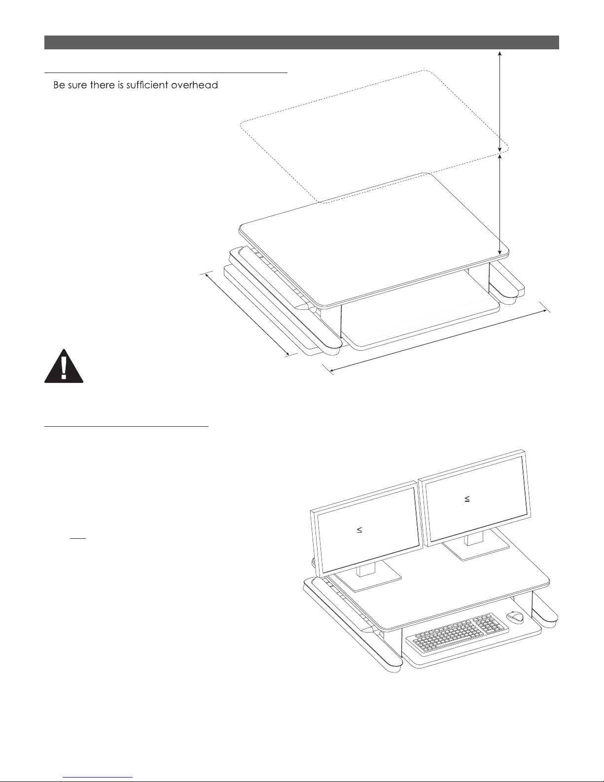
Position the S2S Assembly on the Work SurfacePosition the S2S Assembly on the Work Surface
•
space for the product and monitor(s)
to rise to the maximum height.
— The top of the product rises 15.7".
In addition, allow at least 18" for
monitor height. See figure 2.
WARNING: Do not allow any part
WARNING:
of the base of this product to hang
over the edge of the work surface!
24”
36"
Monitor
Height:
18"
(457mm)
Rise:
15.7"
(400mm)
Figure 1
Place Monitor(s) and Keyboard
The S2S Sit-To-Stand product can accomodate up to two monitors. However, certain dimension
and weight limitations must be observed.
• The combined weight of all added components should not
exceed 35 lbs.
• If two monitors are used, the monitors and other items
on the unit must be equal to or less than 24" wide.
• Do not connect any cords or cables at this time.
Wait until after you test operation and have made
any necessary adjustments.
CAUTION: Do not exceed maximum listed weight
capacity. Serious injury or property damage may
occur.
24"
24"
Figure 2
3
Page 4

S2S SIT-TO-STAND SET-UP
Test Operation
• To prevent the unit from abruptly raising up, hold the top of the unit while squeezing the paddle lever. Raise
the unit to its maximum height and release the lever.
CAUTION: Keep both hands on the top platform to control the rate of movement when operating the
paddle lever. Be prepared to release the lever immediately if it appears there is not enough clearance
for the monitor(s).
• Check that there is at least 1" of clearance between the top of the monitor(s) and any overhead
obstructions.
• Squeeze the paddle lever again and press the top platform down to its lowest level.
• Ideally, it should take about the same amount of force to raise the unit as it does to lower it. If there is a
4
Paddle
Lever
Page 5

ADJUSTMENT S2S SIT-TO-STAND
Make Any Necessary Adjustments
If the product operates to your satisfaction, there is no need to make any adjustments. You may skip to
“Final Set-Up” on page 6.
The two possible adjustments are for keyboard platform projection (below) and load weight (page 6).
Increase Keyboard Platform Projection
• To project the keyboard platform approximately 13/4
remove the 12 screws holding the platform in place.
— This adjustment may be performed with the unit inverted or with the unit upright. The inverted method
is shown below for illustration clarity.
• After removing the screws, move the platform forward and re-attach the screws.
4mm Allen Key
Remove
12 Screws
5
Page 6

2S SIT-TO-STAND ADJUSTMENT
Adjust for Load Weight
This adjustment can be used to maximize ease of operation. When operating this product, the platform
should move easily to any position and hold that position.
•
•
–
).
• Use the 6mm ratchet wrench to turn the adjusting mechanism — counterclockwise to increase load,
clockwise to decrease it. The ratchet only turns one direction, therefore if it doesn’t turn, flip it over.
• Test operation and re-adjust as necessary.
CAUTION: Do not overtighten the MAX (+) adjustment.
Tool storage
• When finished, the ratchet and Allen key can be stored in the built clips on the underside of the worksurface.
Note: 180° lock-out feature must be utilized with monitor
arms.
6mm Wrench
Final Set-Up
• Move the unit to its maximum height.
• Connect the monitor cable(s) and power cord(s), as well as the
keyboard and mouse cords, if applicable.
— Use extensions, if necessary. The cables and cords must reach
their connections when the unit is at its highest point.
• Use the circular clips at the bottom rear of the top platform to
capture the cables and cords.
6
Page 7

800.833.3746 esiergo.com
© 2017 ESI Ergonomic Solutions. All rights reserved. S2S Rev B 5/17
 Loading...