

Page 1
Tel: (303) 469-9322
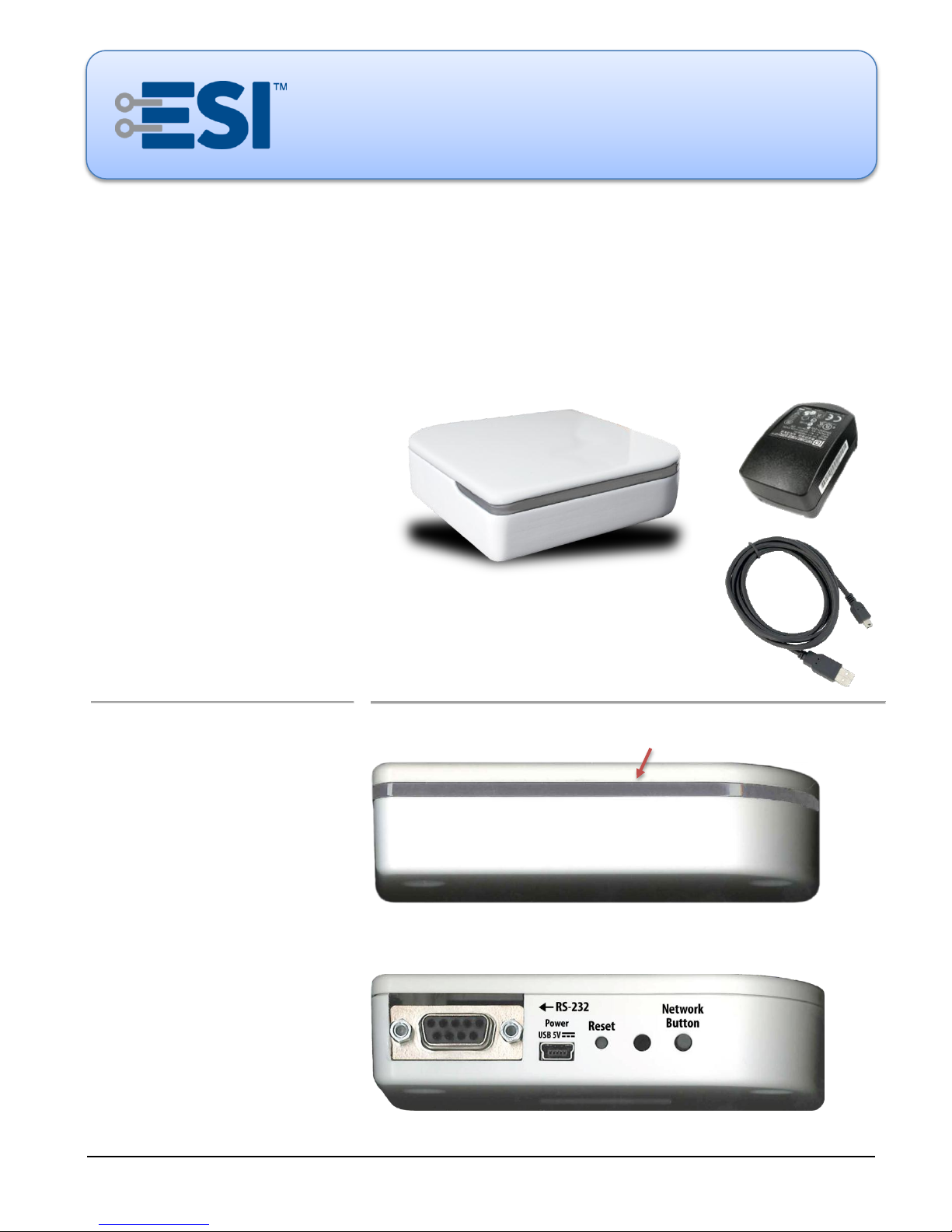
Included:
ESI RF Bridge.
ESI RF Antenna 2.4 GHz (onboard).
External power supply 5 volt DC, 1A
(with interchangeable domestic /
international AC plugin adapters).
USB to Mini-B cable, 3 feet
(for external power supply).
Usage:
Indoor Use in Dry Locations Only.
Not Included:
SUITE remote.
PC computer.
RS-232 serial cable.
USB Port:
The USB port is only for power, not
data.
Use only the 5 volt DC external power
supply provided.
FRONT
BACK
LED
Electronic Solutions, Inc.
ESI RF BRIDGE
User Guide — DRAFT, rev 4
1355 Horizon Avenue
Lafayette, CO 80026 U.S.A.
www.elec-solutions.com
Introduction
The ESI RF Bridge translates between ESI RF communication and serial ASCII strings via an RS-232 connection.
The messages can be similar to RQ Bridge, which allows ESI RF products to be controlled by Home Automation
Systems, Building Management Systems, or other RS-232 sources with existing ESI RQ drivers. The ESI RF
Bridge communicates to ESI RF devices (motors and the RF Switch Interface) and RQ devices (motors and motor
controls) using the ESI RF RQ Transceiver interface.
Parts and Accessories
September 2013, DRAFT rev 4 © 2013 Electronic Solutions, Inc. Page 1 of 13
Page 2
ESI RF BRIDGE User Guide DRAFT, rev 4
Power Up
Observe the ESI RF Bridge LED for initialization during power-up:
9 Yellow, 7 Blue (Beta)
Baud rate
9600 8N1
Flow Control
Xon/Xoff
Echo received characters
Off
End-of-line sequence
CR (carriage return)
Flip position when using RQ
Yes
RQ Address
BSB (may be reassigned)
ESI RF Bridge — Factory Defaults
NOTE: RTS/CTS (hardware flow control) is not available for Beta versions of the ESI RF Bridge but will be
supported in the Production release.
Setup
Hardware Requirements
ESI RF Bridge (with 5 volt DC power supply and USB to Mini-B cable).
PC computer or laptop with DB-9 style (DE-9) serial port, or USB port for a USB Serial Adaptor cable.
o Terminal program for the PC, such as HyperTerminal or Tera Term.
o RS-232 male to female cable or USB Serial Adaptor cable (USB with DB-9 style male connector).
OPTIONAL: SUITE remote, to provide an additional method of motor administration and control, in
addition to the automation system.
Terminal Emulator Settings
Serial Port Settings: 9600 baud, 8 bits, 1 stop bit, no parity
Flow Control: Software Xon/Xoff
Local Echo: off
Do not insert a linefeed after CR.
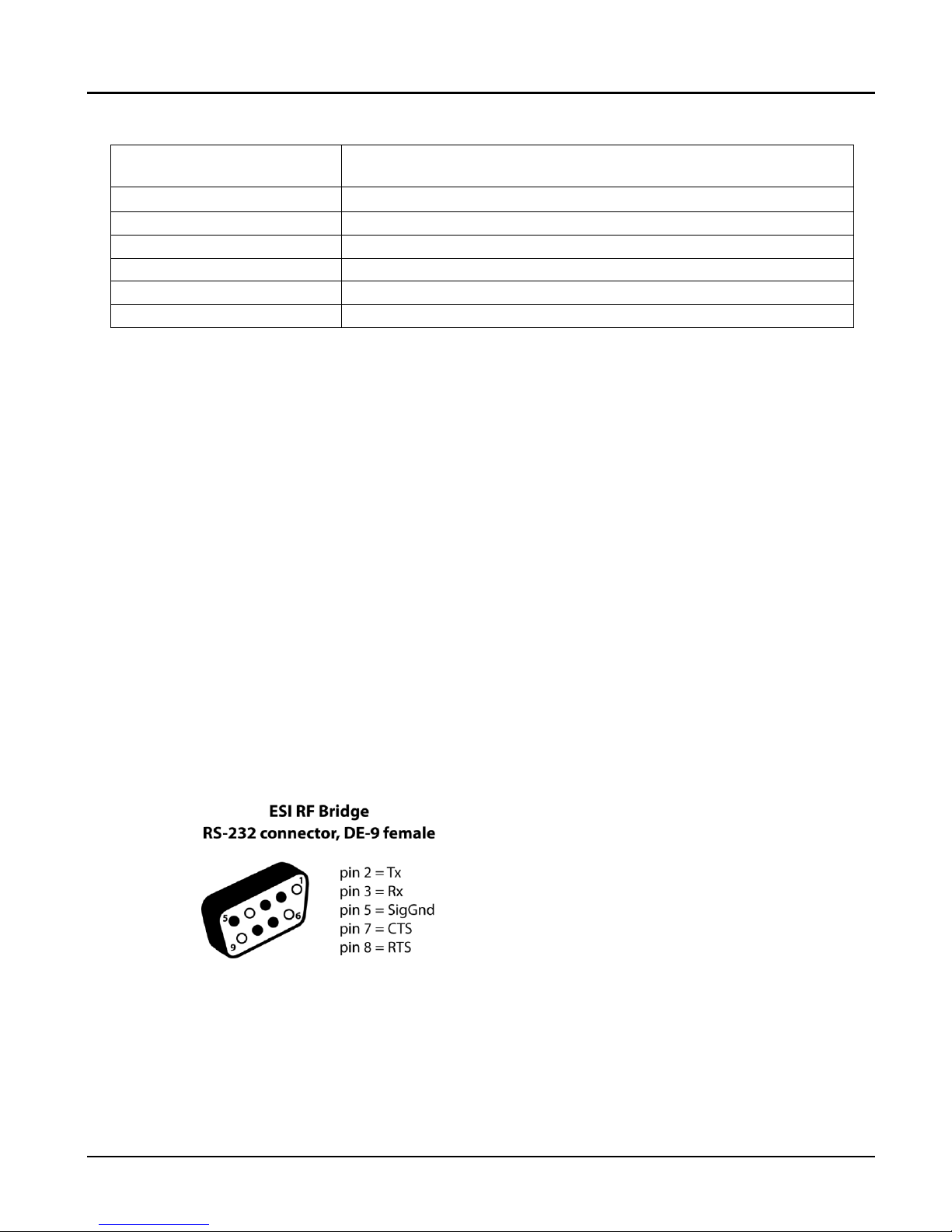
RS-232 Cable and Pinout
Standard DB-9 style to DB-9 style RS-232 serial cables are used to connect a PC/laptop or automation
system to the ESI RF Bridge.
NOTE: the CTS and RTS wires can be omitted when using Xon/Xoff flow control.
1. Hook it up. (also, see the Specifications and Installation Instructions document)
a. Turn on PC and configure terminal program to the correct terminal emulator settings.
b. Connect the RS-232 cable (or USB Serial Adaptor cable) from the PC to the RS-232 port on the ESI RF
Bridge.
c. Connect the “USB to Mini-B” cable from the 5 volt DC external power supply to the ESI RF Bridge.
NOTE: The USB ports are only for power, not data. Plug the cable into the power supply provided.
www.elec-solutions.com © 2013 Electronic Solutions, Inc. Page 2 of 13
Page 3
ESI RF BRIDGE User Guide DRAFT, rev 4
2. Apply power to the ESI RF Bridge.
a. Plug in the 5 volt DC external power supply to AC power.
b. Observe the ESI RF Bridge LED for initialization during power-up.
Version blink: 9 Yellow, 7 Blue (Beta)
c. A serial string is sent to the PC or automation system.
Serial string: !BSBv0.9.7.1 (NOTE: version “0.9.7.1” is shown; the beta version number may be different.)
3. Configure the ESI RF Bridge.
Use the terminal emulator to configure the ESI RF Bridge and send commands to the RQ devices and RF
devices in the network.
In the Terminal Emulator:
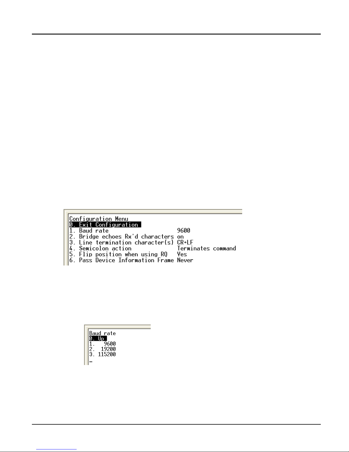
a. Press Ctrl-C to launch the Configuration Menu (see the “Configuration Menu items” table below for an
explanation of the Configuration Menu settings).
Only the last item in the Configuration Menu shows in the terminal emulator. To see all of the
menu items, turn on the Echo and Linefeed characters using the next two steps.
b. Press the “2” key.
Sets Echo to “on” to see Rx characters on the screen.
c. Press the “3” key.
Sets the line termination character to CR+LF (carriage return and line feed).
Configuration Menu:
d. OPTIONAL: change the Baud Rate.
1. Press the “1” key OR use an arrow key to choose the “1.” entry in the Configuration Menu, then
press the Enter key.
2. In the Baud Rate sub-menu, press the “1” “2” or “3” key OR use an arrow key to choose the “1.”
“2.” or “3.”entry, then press the Enter key.
Baud Rate sub-menu:
3. Change the Baud Rate in the terminal emulator program on the PC to match the ESI RF Bridge.
4. Power-cycle the ESI RF Bridge.
NOTE: the Baud Rate does not change until power is turned off, then turned on.
To return to the Configuration Menu from the Baud Rate sub-menu:
Press the “0” key OR use an arrow key to choose the “0.” entry, then press the Enter key.
www.elec-solutions.com © 2013 Electronic Solutions, Inc. Page 3 of 13
Page 4

ESI RF BRIDGE User Guide DRAFT, rev 4
Configuration Menu Entry
Default Setting
Description
0. Exit Configuration
n/a
Exits the ESI RF Bridge configuration menu.
1. Baud rate
9600
Choices:
9600, 19200, 115200
2. Bridge echoes Rx’d characters
off
Choices:
off = do not echo characters to the display.
on = echo characters to the display.
3. Line termination character(s)
CR
Choices:
CR = moves the cursor to the beginning of the same
line.
CR+LF = moves the cursor to the beginning of the
next line.
4. Semicolon action
Terminates
command
Choices:
Terminates command = parses and transmits single
commands each time a semicolon or CR is received.
Separates commands = allows multiple commands to
be received before processing. Commands are parsed
and transmitted after a CR is received.
5. Flip position when using RQ
Yes
Choices: See NOTE 1 below.
Yes = position reports from RF devices are flipped to
match the position reporting scheme of RQ devices.
No = position reports from RF devices are not flipped.
6. Pass Device Information Frame
Never
Choices: See NOTE 2 below.
Never = do not transmit Device Information Frames
over the serial interface.
When using RF = transmit Device Information Frames
over the serial interface when the last command
received was an RF command and not an RQ
command.
Always = transmit Device Information Frames over the
serial interface whenever one is received from an RF
device.
e. OPTIONAL: change other settings, by choosing the item in the Configuration Menu, and making a
selection in the sub-menu that appears.
f. Exit Configuration: Press the “0” key or use an arrow key to choose the “0.” entry in the Configuration
Menu, then press the Enter key.
Configuration Menu items
NOTE 1
a. By default, RQ devices report 99 percent when at the fully closed limit, and 0 percent when at the fully open limit,
with the exception of the FOREST Shuttle® motor, where 0 percent is the fully closed limit.
b. By default, RF devices report 0.0 percent when at the fully closed limit, and 99.9 percent when at the fully open limit.
c. When the RQ protocol is used, the position is reported as two digits (0-99) from RQ devices that use the ESI RF RQ
Transceiver.
d. When the RF protocol is used, the position is reported as two digits (0-99) from RQ devices, and as three digits
(0.0-99.9) from RF devices.
NOTE 2
a. A Device Information Frame is an RF protocol message that contains detailed information about an RF device.
www.elec-solutions.com © 2013 Electronic Solutions, Inc. Page 4 of 13
Page 5

ESI RF BRIDGE User Guide DRAFT, rev 4
ESI RF Bridge
ACTION
RESULTS
Hub Device
Designation for the ESI RF
Bridge when powered up.
IMPORTANT:
The ESI RF Bridge is always the Hub Device in an ESI RF
network. No other device can be the Hub Device.
Jog Once
Device moves a short distance in one direction.
Jog Twice
Device moves a short distance in one direction, then moves a
short distance in the opposite direction.
Join a Network
While Network Invite is active on the
SUITE remote and ESI RF Bridge:
Plug in each ESI RF motor.
Plug in each ESI RF RQ Transceiver
to a powered RQ device.
Device jogs once to indicate the ESI RF or RQ device successfully
joined the network.
Network Button
Triple press within 1 second
A reset that clears network information. The Yellow LED blinks
Create an ESI RF Network
The ESI RF Bridge communicates with all ESI RF devices as well as RQ motor controls or Q motors that are
connected to ESI RF RQ Transceivers.
Initial Conditions
ESI RF Bridge
Powered up, connected to a PC or automation system, and configured.
ESI RF Devices
To use ESI RF commands from the terminal emulator or automation system, the motor can be in either of the
following two conditions:
motor at factory defaults and unplugged, or
motor with limits set, network information cleared, and unplugged.
To use RQ commands from the terminal emulator or automation system, the motor must be in this condition:
motor with limits set, network information cleared, and unplugged.
NOTE: you can use the motor head buttons or a SUITE remote to set limits on an ESI RF motor.
SUITE remote at factory default and asleep.
For details about using a SUITE remote in an ESI RF network, see the M40/50RF System Quick
Setup Guide on the ESI website: SUITE Arc web page.
RQ Devices
Prepare RQ devices for incorporation into an ESI RF network, but do not plug in the ESI RF RQ Transceiver.
1. The RQ device must be in the following state before connecting to an ESI RF RQ Transceiver:
a. Factory Default — all options set to factory default.
b. Limits set:
i. If RQ control, limits on the motor being controlled must be set and the control
calibrated.
ii. If RQ motor, the limits must be set.
c. Calibrated.
2. Follow the setup instructions in the ESI RF RQ Transceiver Install Guide on the ESI website:
ESI RF RQ Transceiver web page.
3. The RQ device — motor or motor control — must be powered up. The ESI RF RQ Transceiver will be
connected in a later step. A motor control must have a motor connected, to provide feedback (jog), as
an ESI RF network is set up.
Definitions
www.elec-solutions.com © 2013 Electronic Solutions, Inc. Page 5 of 13
Page 6

ESI RF BRIDGE User Guide DRAFT, rev 4
ESI RF Bridge
ACTION
RESULTS
twice, then the Blue LED blinks twice (indicates the ESI RF Bridge
is a Hub Device). A serial string with the version number is sent to
the PC or automation system.
Single press
Starts Network Invite. Use only when the Yellow LED is off, and
you want to join a ESI RF devices and a SUITE remote to the ESI
RF network.
The Yellow LED flashes indefinitely.
Single-press the Network Button again to turn off Network
Invite (Yellow LED stops flashing).
Press and hold for 10 seconds, until
Yellow LED blinks once, then release.
A partial reset that resets the Baud Rate and Terminal Emulator
settings for the ESI RF Bridge.
Reset Button
Single press
A full reset of the ESI RF Bridge to factory default.
The Blue LED blinks twice to indicate the ESI RF Bridge is a
Hub Device.
A serial string with the version number is sent to the PC or
automation system.
Network Invite
Press Network Button on ESI RF Bridge.
Press STOP button on SUITE remote.
The time frame while the Hub Device allows other ESI RF devices
to join the network.
ESI RF Bridge: Yellow LED flashes indefinitely.
SUITE Remote: Green LED flashes for 60 seconds.
Network Search
Press PRESET, UP, STOP, or DOWN
button on SUITE remote when remote is at
factory default and asleep.
The 30 second time frame while a remote looks for ESI RF
devices to join when no network is present. On the remote, the
Green LED is on solid.
Steps
1. Verify that no devices are currently joined to the ESI RF network:
a. In the terminal emulator, press Ctrl-T to show the Device List.
b. If the Device List is empty, continue with Step 2.
Empty Device List:
c. If the Device List contains devices, then triple-press (within 1 second) the Network Button on the
ESI RF Bridge.
The Yellow LED blinks twice, then the Blue LED blinks twice.
A serial string with the version number is sent to the PC or automation system.
d. In the terminal emulator, press Ctrl-T to show the Device List, which should be empty. Continue
with Step 2.
www.elec-solutions.com © 2013 Electronic Solutions, Inc. Page 6 of 13
Page 7

ESI RF BRIDGE User Guide DRAFT, rev 4
2. On the ESI RF Bridge, press the Network Button once, to start Network Invite.
a. The Yellow LED is flashing (and remains flashing until the Network Button is pressed again).
3. On the SUITE remote:
a. Press the PRESET, UP, STOP, or DOWN button to “wake up” and initiate Network Search.
Green PRESET LED is on solid.
b. After a few seconds, the SUITE remote joins the ESI RF network.
The Group 1 LED is on solid, and the Red PRESET button is on solid.
4. On the SUITE remote:
a. Press and release the STOP button to initiate Network Invite.
Green LED under PRESET flashes for up to 60 seconds while Network Invite is active.
5. While Network Invite is active on both the SUITE remote and ESI RF Bridge, apply power to each ESI
RF motor and if there are RQ devices, plug in an ESI RF RQ Transceiver to each RQ device, until all
devices are joined to the network.
a. Each device will jog once when it joins the network (within a few seconds).
6. On the ESI RF Bridge, press the Network Button once to stop Network Invite.
a. Yellow LED turns off.
7. In the terminal emulator, press Ctrl-T to show the Device List. Verify that all devices successfully joined
the network. Below is an example of a Device List with six devices. The ESI RF Bridge does not show in
the Device List.
NOTE: The RQ address of each device is automatically reassigned, to 3 digit numbers in ascending
order, for example: 001, 002, 003, and so on.
NOTE: For the Type of device: 01 is a SUITE remote, and 06 is an ESI RF motor or ESI RF RQ
Transceiver (connected to a Q motor or RQ motor control).
Populated Device List:
8. Configure the ESI RF network:
a. Use the SUITE remote to configure the ESI RF network (Set Limits and so on), OR
b. In the terminal emulator or automation system, use the RQ commands listed in the next section to
configure the ESI RF network.
IMPORTANT: If you are not using a SUITE remote in the ESI RF network, you must set limits on
ESI RF motors first, in order to use RQ commands from the terminal emulator to
configure and control those motors.
www.elec-solutions.com © 2013 Electronic Solutions, Inc. Page 7 of 13
Page 8

ESI RF BRIDGE User Guide DRAFT, rev 4
Start Character
Address
Command
Data
End Character
!
BSB v ?
;
RQ
Command
Data
Description
Example
Response
Notes
@
3 characters
(0-9 or A-Z)
Re-address the ESI RF
Bridge
!BSB@RF1;
Address change report
Change the address from BSB
to RF1.
9. If the ESI RF Bridge will be connected to an automation system after the ESI RF network is set up, then
you must reverse the Echo (On) and Line Termination character (CR+LF) that were turned on previously
in the Configuration Menu. In the terminal emulator:
a. Press Ctrl-C to enter the Configuration Menu.
b. Press the “2.” key.
c. Press the “3.” key.
d. Press the “0.” key to exit the Configuration Menu.
10. Disconnect the PC from the ESI RF Bridge.
11. Connect the ESI RF Bridge to an Automation System.
12. Put the SUITE remote into User Mode, for handoff to the customer.
RQ Message Format — Overview
An RQ message always begins with a Start Character “!” (a.k.a. Bang) and ends with an End Character “;”
(semicolon). There will always be an Address (3 ASCII characters) and a Command (1 ASCII character) as
shown in the table below. In some cases, the Data field is a variable number of characters or no Data. A “?”
(question mark) in the Data field signifies a request message. For Downlink messages, the End Character is “;” or
<CR> (both are treated the same). For Uplink messages, the End Character can be set using the ESI RF Bridge
Configuration Menu to be “;” or <CR>.
RQ Addressing is always three ASCII characters composed of only 0-9 and A-Z. For the case where an address
is 000 — the global command — all RF nodes networked to the ESI RF Bridge are being addressed and for that
reason, no node can have 000 as its address. The ESI RF Bridge is factory addressed at BSB. RQ devices are
given random addresses from the factory (first character will be between “C” and “Z”).
Uplink
Messages from the RF nodes, relayed to the PC/automation system via the ESI RF Bridge.
Downlink
Messages from the PC/automation system, relayed to the RF nodes via the ESI RF Bridge.
The following is an example of a Downlink message from the PC/automation system to the ESI RF Bridge
requesting its version. The literal command string is “!BSBv?;”
Improperly formatted Downlink messages or message content that is out of range will cause the message to be
discarded by the ESI RF Bridge and an Uplink error message generated.
Valid RQ Commands
The RQ commands/messages in the table below are valid when sent to the ESI RF Bridge from a PC or
automation system, or received by the ESI RF Bridge from an RF node.
BSB = the default RQ address of the ESI RF Bridge.
!BSBU; U = undefined or invalid message.
www.elec-solutions.com © 2013 Electronic Solutions, Inc. Page 8 of 13
Page 9

ESI RF BRIDGE User Guide DRAFT, rev 4
RQ
Command
Data
Description
Example
Response
Notes
A
3 characters
(old address)
Acknowledge address
change
!RF1ABSB;
(address report)
This device’s address was
changed from BSB to RF1.
v
?
Report version
!BSBv?;
!BSBv0.9.7.1;
The ESI RF Bridge’s firmware
version is 0.9.7.1
v
?
Report version
!002v?;
!002v1.3.4.1;
This device’s firmware version
is 1.3.4.1
NOTE: the SUITE remote is
not a node, and will not report
it’s firmware version number.
o
Move open
!002o;
No report.
No report if RF device does
not have limits set or RQ
device connected to ESI RF
RQ Transceiver is not
calibrated.
c
Move close
!002c;
No report.
No report if RF device does
not have limits set or RQ
device connected to ESI RF
RQ Transceiver is not
calibrated.
s
Stop
!002s;
No report.
No report if RF device does
not have limits set or RQ
device connected to ESI RF
RQ Transceiver is not
calibrated.
i
Identify
!002i;
No report.
Motor jogs once.
Used to identify which motor is
assigned to an RQ address.
m
destination*
(00-99)
Move to intermediate
position (2 digit)
!002m23;
No report.
Moves to 23% away from
reference.
No report if RF device does
not have limits set or RQ
device connected to ESI RF
RQ Transceiver is not
calibrated.
M
destination
(000-999)
Move to intermediate
position (3 digit)
!002M237;
No report.
Moves to 23.7% away from
reference.
No report if RF device does
not have limits set or RQ
device connected to ESI RF
RQ Transceiver is not
calibrated.
r
?
Request 2 digit position
now
!002r?;
2 digit position
report if stopped.
!002r23;
Motor is stopped 23% away
from reference.
No report if RF device does
not have limits set or RQ
device connected to ESI RF
RQ Transceiver is not
calibrated.
R
?
Request 3 digit position
now
!002R?;
3 digit position
report if stopped.
Not supported in Beta, but
will be supported in
Production release.
No report if RF device does
www.elec-solutions.com © 2013 Electronic Solutions, Inc. Page 9 of 13
Page 10

ESI RF BRIDGE User Guide DRAFT, rev 4
RQ
Command
Data
Description
Example
Response
Notes
not have limits set or RQ
device connected to ESI RF
RQ Transceiver is not
calibrated.
NOTE: Scenes cannot be “defined” while the motor is moving.
d
scene s
Define a scene
!002dC23;
No report.
RQ device jogs twice and does
not move to the scene.
RF motor jogs twice, then jogs
twice again, and does not
move to the scene.
NOTE:
By default, Scene “0” is used
for the PRESET button on the
SUITE remote. A different
scene number for the PRESET
button can be used.
g
scene s
Execute scene
!000gC;
All motors go to
scene C (if they are
included in the
scene).
If the scene is selected, no
response if already at position.
No response if the scene is not
selected.
RQ
Command
Data
Description
Send
Response
Notes
v
?
Report version
!000v?;
!BSBv0.9.7.1;
(ESI RF Bridge
reports first
... followed by
reports from
all RF nodes)
The ESI RF Bridge’s firmware
version is 0.9.7.1, followed by
the address and firmware
version of all RF nodes.
NOTE: the SUITE remote is not
a node, and will not report it’s
firmware version number.
* 00 means at reference (for RQ, default = open), 99 means at limit away from reference (closed). The percents can be flipped when
using the “Flip position” option in the Configuration Menu of the ESI RF Bridge.
NOTE: positions may not be evenly spaced depending on method of lift and motor response to load.
NOTE: 2 digit positions repeat the 1st digit as the 3rd digit to evenly space the fractional part. For example: 27% is converted to
27.2%. When a position is reported as 2 digits, the 3rd digit is ignored (not rounded).
s
Scene number is one of 62 possible: from 0 to 9, A to Z, a to z
Global RQ Command
The ESI RF Bridge responds to a global version request and then passes the message Downlink and all RF
nodes will respond with a version report.
000 = the global address to all RF nodes.
BSB = the default RQ address of the ESI RF Bridge.
www.elec-solutions.com © 2013 Electronic Solutions, Inc. Page 10 of 13
Page 11

ESI RF BRIDGE User Guide DRAFT, rev 4
RQ
Command
Data
Description
Send
Response
Notes
~
Randomize the ESI RF
Bridge’s RQ address
!BSB~;
!BSBU;
Not allowed. ~
Randomize the RQ
address of all RQ devices
!000~;
!BSBU;
Not allowed. ~
Randomize the RQ
address of one RQ device
!002~;
!BSBU;
Not allowed.
@
3 characters
(0-9 or A-Z)
Re-address all nodes
!000@AAA
!BSBU;
Illegal command.
d
scene
s
NS
Clear a scene
!002dCNS;
Currently not implemented.
Do not act on scene “C”.
d
- (minus sign)
Clear all scenes
!002d-;
Currently not implemented.
Do not act on any scene.
N
?
Request the ESI RF
Bridge’s default name
!BSBN?;
!BSBU;
Not allowed.
The name parameter is not
supported on the ESI RF Bridge
or on RF nodes networked to
the ESI RF Bridge.
N
1-16
characters
Assign a name to the ESI
RF Bridge
!BSBNrf_bridge;
!BSBU;
Not allowed.
Cannot assign a name to the
ESI RF Bridge.
Unsupported RQ Commands
These RQ commands are not supported when sent to an ESI RF Bridge from a PC or automation system.
Valid RF Commands
NOTE: RF commands will be fully supported in the Production release.
www.elec-solutions.com © 2013 Electronic Solutions, Inc. Page 11 of 13
Page 12

ESI RF BRIDGE User Guide DRAFT, rev 4
Usage
Indoor Use in Dry Locations Only.
Ordinary Protection (not protected against harmful ingress of moisture).
Power
USB power draw from the USB 5VDC Power Supply: 5VDC 1A max (<0.1A typical)
Frequency
2.4 GHz
Operating Temperature
Range
+41°F to +95°F (+5°C to +35°C)
Transportation and
Storage Temperatures
0°F to +120°F (-18°C to +49°C)
Maximum Altitude
0 to 13,500 ft (4,115 m)
Weight
ESI RF Bridge:
0.26 lb (0.12 kg)
Dimensions
ESI RF Bridge:
Width: 3.81 in (96.7 mm)
Height: 3.81 in (96.7 mm)
Depth: 0.93 in (23.6 mm)
Listed Accessories
External USB 5VDC power supply.
USB cable.
Interchangeable AC plugin adaptors (domestic and international).
Cleaning Instructions
ESI RF Bridge:
1. Disconnect power.
2. Unplug cable and power cord.
3. Wipe the device’s outside surface lightly with a clean, soft cloth dampened
with water.
Optional Remote Control:
1. Wipe the device’s outside surface lightly with a clean, soft cloth dampened
with water.
Specifications
No serviceable parts are included.
Safety Instructions
Also, see the Installer’s Manual & Instructions before using this product.
WARNING:
Important safety instructions. It is important for the safety of persons to follow these instructions. Save these
instructions.
Do not allow children to play with fixed controls. Keep remote controls away from children.
Frequently examine the installation for imbalance and signs of wear or damage to cables. Do not use if
repair or adjustment is necessary.
Please instruct the Operator to disconnect the external power supply, remove the plug of the power
supply cord of the external power supply from the AC Mains Outlet (or remove the wall-mount power
supply from the AC Mains Outlet): please ensure that the Mains Outlet is easily accessible for this
purpose.
www.elec-solutions.com © 2013 Electronic Solutions, Inc. Page 12 of 13
Page 13

ESI RF BRIDGE User Guide DRAFT, rev 4
FCC ID: P7RRFBRIDGE
This equipment has been tested and found to comply with the limits for a Class B digital
device, pursuant to part 15 of the FCC Rules.
IC: 7206A-RFBRIDGE
This Class B digital apparatus complies with Canadian ICES-003.
This symbol means that this product complies with the European Union Harmonised
Standards for the Low Voltage Directive and EN 60335-1: 2012
This symbol means that this product complies with International Standard EN 55011: 2007
and AS/NZS 4268: 2008
This symbol cautions the user to refer to all of the instructions and warnings specified in the
User Guide and the Installer’s Manual & Instructions before using this product.
This symbol indicates an RS-232 port.
This symbol means that this product must be disposed of separately from household waste
and must be disposed of according to local laws and regulations for electrical and electronic
waste.
Regulatory Compliance
This device complies with part 15 of the FCC Rules. Operation is subject to the following two conditions: (1) This device may not
cause harmful interference, and (2) this device must accept any interference received, including interference that may cause
undesired operation.
Le présent appareil est conforme aux CNR d'Industrie Canada applicables aux appareils radio exempts de licence. L'exploitation
est autorisée aux deux conditions suivantes : (1) l'appareil ne doit pas produire de brouillage, et (2) l'utilisateur de l'appareil doit
accepter tout brouillage radioélectrique subi, même si le brouillage est susceptible d'en compromettre le fonctionnement.
This Class B digital apparatus complies with Canadian ICES-003.
This device complies with Industry Canada license-exempt RSS standard(s). Operation is subject to the following two conditions:
(1) this device may not cause interference, and (2) this device must accept any interference, including interference that may
cause undesired operation of the device.
This equipment has been tested and found to comply with the limits for a Class B digital device, pursuant to part 15 of the FCC
Rules. These limits are designed to provide reasonable protection against harmful interference in a residential installation. This
equipment generates, uses and can radiate radio frequency energy and, if not installed and used in accordance with the
instructions, may cause harmful interference to radio communications. However, there is no guarantee that interference will not
occur in a particular installation. If this equipment does cause harmful interference to radio or television reception, which can be
determined by turning the equipment off and on, the user is encouraged to try to correct the interference by one or more of the
following measures:
—Reorient or relocate the receiving antenna.
—Increase the separation between the equipment and receiver.
—Connect the equipment into an outlet on a circuit different from that to which the receiver is connected.
—Consult the dealer or an experienced radio/TV technician for help.
Changes or modifications not expressly approved by the party responsible for compliance could void the user's authority to
operate the equipment.
If the equipment is used in a manner not specified by the manufacturer, the protection provided by the equipment may be
impaired.
Disclaimer
Information in this document is subject to change without notice. The manufacturer does not make any representations or
warranties (implied or otherwise) regarding the accuracy and completeness of this document and shall in no event be liable for
any loss of profit or any commercial damage, including but not limited to special, incidental, consequential, or other damage.
www.elec-solutions.com © 2013 Electronic Solutions, Inc. Page 13 of 13
 Loading...