

ESI Kata2-MS Series, KATA2-MS-DC-BLK, KATA2-MS-DC-WHT, KATA2-MS-GM-SLV, KATA2-MS-GM-BLK Installation Instructions Manual
...Page 1
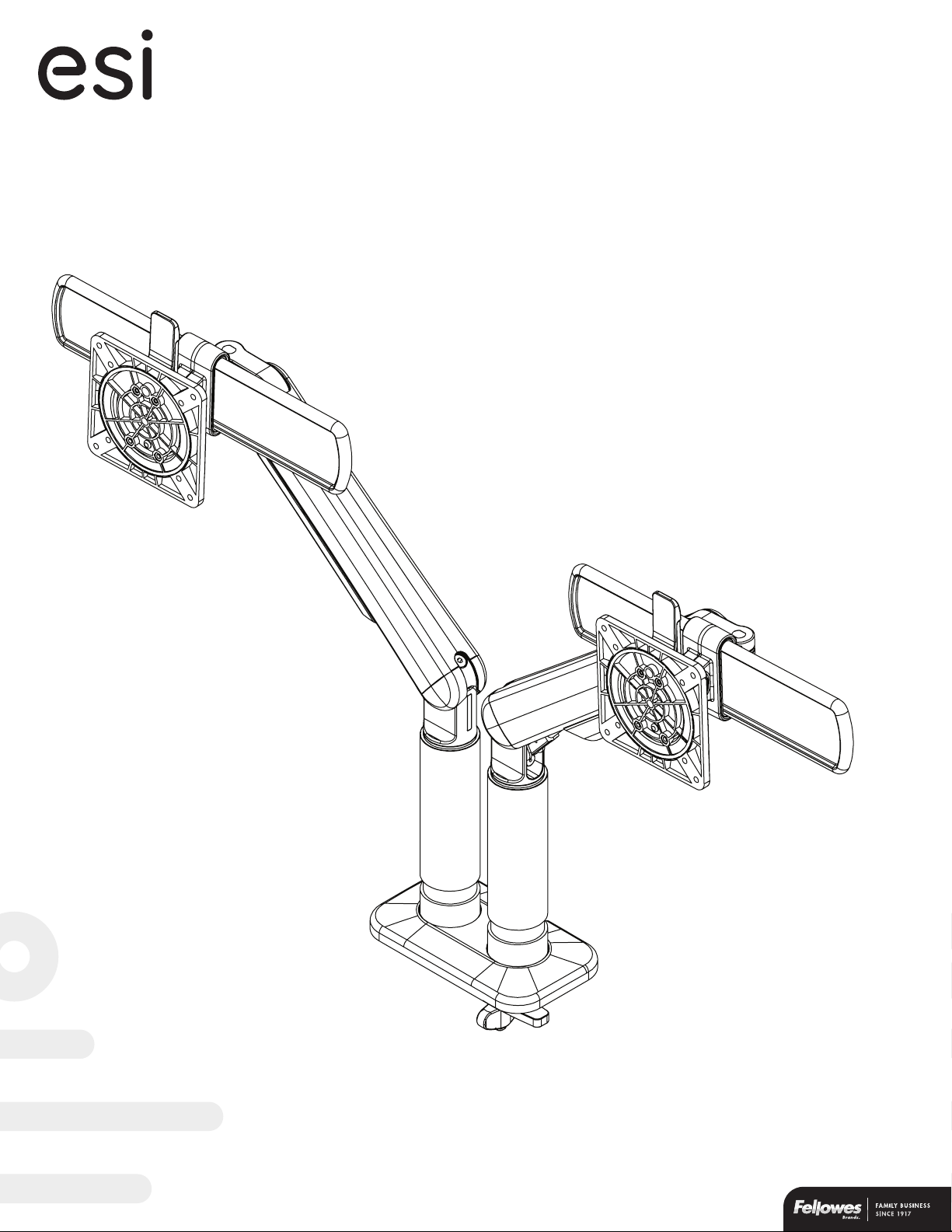
Kata2-MS
™
installation instructions
dual monitor arm with sliders
Model #KATA2-MS-DC-SLV
Model #KATA2-MS-DC-BLK
Model #KATA2-MS-DC-WHT
Model #KATA2-MS-GM-SLV
Model #KATA2-MS-GM-BLK
Model #KATA2-MS-GM-WHT
Page 2
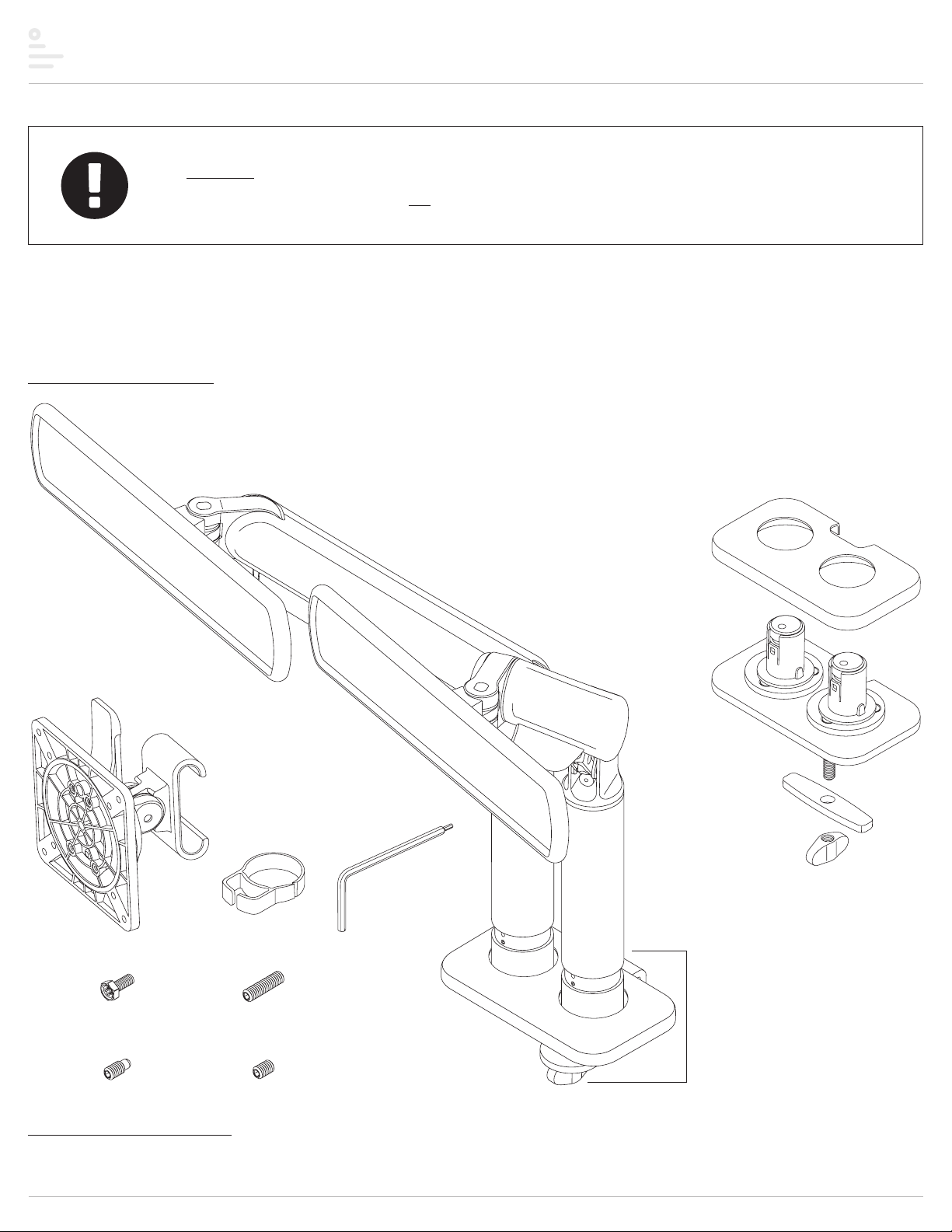
Kata2-MS Components and tools
Caution
• Hand tighten screws only. Do not use power tools.
Please review these instructions before beginning the installation. Use the illustrations below to check that all the components needed for your
installation were provided with your order. Do not discard the packaging until the product works to your satisfaction.
Components and tools
for clamp mounting method:
monitor arm assemblies (2) and
clamp base assembly (1)
for both mounting methods:
VESA mount assemblies (2)
for optional
grommet mounting method:
monitor arm assemblies (2), plus...
grommet base cover (1)
grommet base assembly (1)
grommet bar (1)
grommet knob (1)
VESA plate screws (8)
M4x10
VESA locking screws (2)
M4x6 set screws (2)M4x9 set screws (4)
Additional tools required
• Phillips screwdriver
cable clips (2)
M4x15
dual Allen key (1)
2mm and 4mm
clamp base assembly
not included when
optional grommet
mounting is ordered
Page 2
Page 3
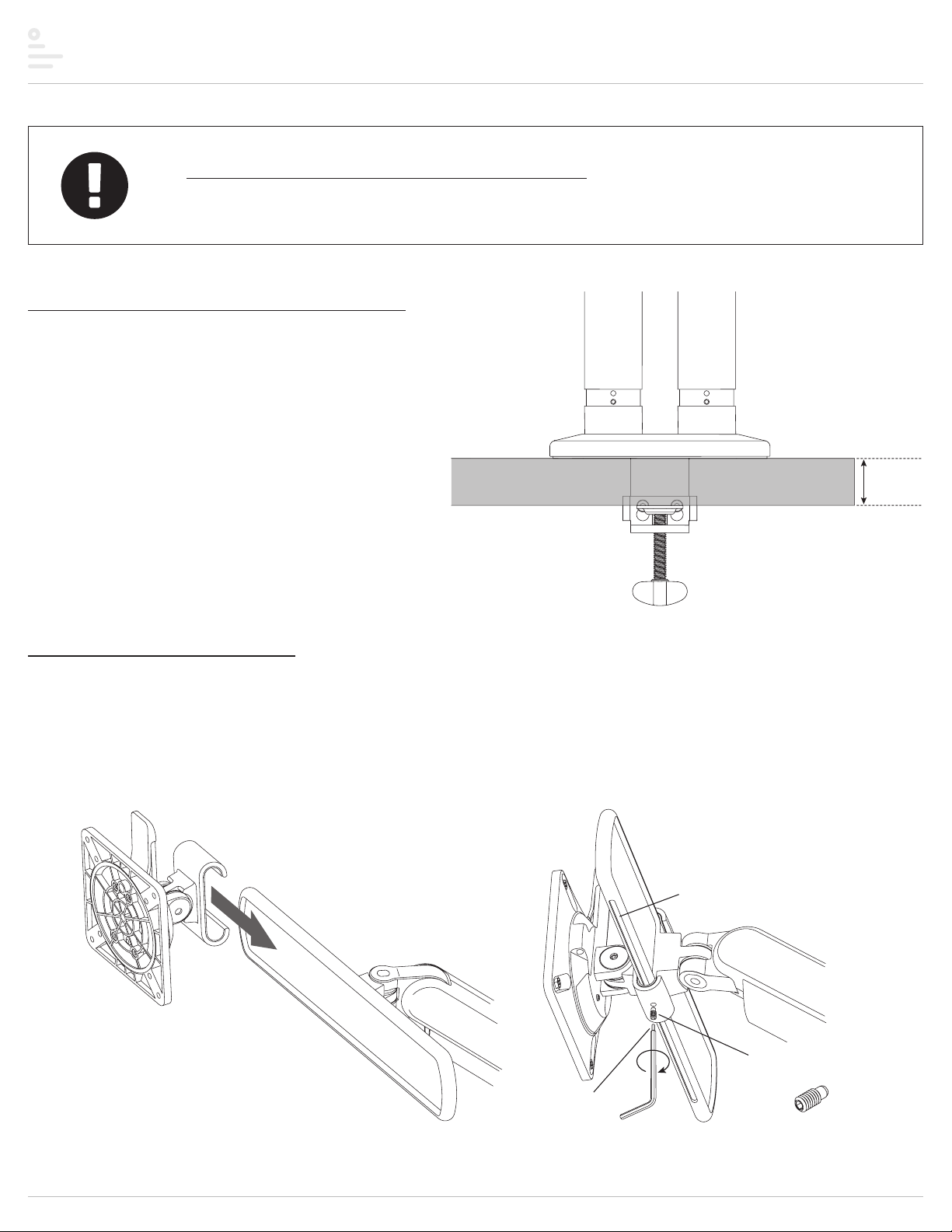
Kata2-MS Assembly
If using optional grommet mounting method:
• Replace step 1 with steps A and B on page 7. Then return to this page and start with step 2 below.
Step# 1: clamp base assembly to worksurface
The thickness of the worksurface must be between 0.5" and 2.1".
• Loosen the clamp suciently to be able to slide it easily onto the worksurface.
• Clamp the assembly to the worksurface in the desired position. Be sure to
tighten the clamp securely.
0.5" – 2.1"
clamp to
worksurface
Step# 2: assemble slider mounts
IMPORTANT: When assembling the slider mounts, the groove on the slider bar must be at the bottom.
• Slide the VESA mount assembly onto the slider bar. Center the assembly on the slider bar.
• Install the M4x9 set screw into the bottom of the VESA mount assembly. Using the 2mm Allen key, tighten the set screw to hold the assembly in place. Be sure the
screw tip fits into the groove on the slider bar.
— After the monitor has been installed, the VESA mount can be moved anywhere along the slider bar by loosening the locking screw no more than one full turn, so that
it stays inside the groove. Be sure to re-tighten the screw to secure the monitor in the desired position.
groove
VESA mount
assembly
slider bar
slider mount set screw
M4x9
2mm
Allen key
Page 3
Page 4

Kata2-MS Assembly
Step #3: attach VESA plates to monitors
• Remove each VESA plate from its VESA mount by pushing forward the tab at the top and lifting upward.
— TIP: Practice re-installing the VESA plate before attaching it to the monitor. This will make step 3 easier.
• Place each monitor face down on a flat surface. Align the VESA plate holes with the holes on the back of the monitors. Attach the VESA plates using the four VESA plate
screws per monitor.
— There are two sets of four holes on the VESA plates. One set has holes 3.9" (100mm) apart, the other set has holes 3" (7f) apart. Use the set that matches the holes
on the rear of each monitor.
2
lift o VESA plate
1
push tab forward
VESA plate screw
VESA
plate
top
3.9"
(100mm)
monitor
(face down)
3"
(75mm)
Step #4: attach monitors to VESA mounts
• Slide each VESA plate (with monitor attached) back onto its VESA mount.
— Make sure the VESA plates click securely in place.
• OPTIONAL: Secure each VESA plate to the VESA mount using the M4x15
VESA locking screw, as shown below.
VESA locking screw
M4x15
2mm Allen key
attach
monitor
VESA
plate
VESA
mount
Page 4
Page 5

dual Allen key
2mm end
Kata2-MS Assembly
slide up
slide
down
Step #5: install lockout set screws, if desired
Default rotation of the monitor arm assemblies
is 360°. Installation of lockout set screws limits
rotation to 180°.
• To lockout rotation of a monitor arm assembly,
install a set screw in the upper hole in the
recessed portion of the straight arm. Tighten
the screw, then back it o one turn.
• The monitor arm assembly must be in its
allowed range of rotation when installing
the lockout set screw.
monitors
not shown
M4x9
Step #6: organize cables and cords
• Remove the cable covers from each monitor arm by sliding
them upward.
• Capture the cables and cords with the cable covers. Slide the
cable covers downward to attach them to the monitor arms.
• Snap the cable clips into groove at the bottom of the straight
arms. Position the opening on the clips toward the rear.
• Route the monitor cables and power cords toward the rear
by slipping the cords into the opening on the cable clips.
180°
remove cable
covers
install covers
over cables
capture
cables
with clip
snap on
cable clip
Page 5
Page 6

Kata2-MS Assembly
2
Step #7: make any necessary adjustments
There are five possible ways to change the position of the monitors to maximize the eciency and comfort of the working environment:
1. Monitor position on slider
— To move the monitors from side-to-side, use the 2mm end of the dual Allen key to loosen the set screw (M4x9) on the bottom of the VESA mount assembly, then
slide the monitor along the slider bar. Do not loosen the set screw more than one full turn — the tip of the set screw must remain inside the groove on the slider bar
so that the mount assembly cannot slide o the ends. Re-tighten the set screw when the monitors are positioned where desired.
2. Monitor swivel
— Use the 4mm end of the dual Allen key to adjust the underside screw behind the slider bar for the desired ease of monitor rotation.
3. Monitor arm swivel
— Use the 2mm Allen key to adjust the bottom set screw (M4x6) in the recessed area of the straight arm for the desired ease of rotation.
4. Monitor tilt
— To change monitor tilt angle, use the 4mm Allen key to loosen the screw on the side of the VESA mount. Tighten the screw to hold the angle.
5. Motion arm weight adjustment
— Use the 4mm Allen key to adjust the screw at the top of the fixed arm for the appropriate monitor weight. When adjusted properly, the monitor weight is balanced,
making it easy to raise or lower the monitor.
5
monitors
not shown
behind
slider
M4x6
1
4
3
2
4
5
1
3
Page 6
Page 7

Kata2-MS Optional grommet mount assembly
tighten set screw
Step A: attach grommet base assembly to worksurface
• Place the base assembly over the grommet hole with the bolt centered. Fit the base cover over the base.
• Insert the grommet bar onto the grommet bolt and then screw on the grommet knob. Tighten the grommet knob securely to hold the base assembly in position.
base cover
grommet base assembly
center bolt in grommet hole
grommet bar
maximum thickness = 1.7"
tighten grommet knob to secure
Step B: install monitor arms into grommet base assembly
• Insert the monitor arm assemblies onto the stems on the grommet base. (If necessary, loosen the set screw first.)
— The tabs on the bushings fit into notches in the bottom of the monitor arm assemblies.
• Tighten the set screw on each monitor arm.
• Check the ease of rotation of the monitor arm
assemblies. If you need to adjust it, do so by
loosening or tightening the set screw.
M4x6
install monitor
arm assemblies
tab
Go to step 2 on page 3 and proceed sequentially
Page 7
Page 8

™
Kata2-MS
dual monitor arm with sliders
Please contact Customer Service with any questions or
comments at 800.833.3746 or visit our website at esiergo.com
LIMITED WARRANTY
ESI warrants this product to be free from defects in manufacturing for a period of 15 years from the date of original purchase. This warranty extends only to the original purchaser, and does not apply
if the product has been damaged or fails to function properly as a result of misuse, abuse, modification, alteration, or improper cleaning or maintenance. This warranty does not apply to damage
in shipment caused by carriers, damage caused during installation, normal wear and tear, or excessive use (meaning consistent use in excess of an eight hour shift). ANY IMPLIED WARRANTIES OF
MERCHANTABILITY OR FITNESS FOR A PARTICULAR PURPOSE ARE LIMITED IN DURATION TO ONE YEAR FROM THE DATE OF ORIGINAL RETAIL PURCHASE. ESI’s sole obligation under this warranty or
any implied warranty, and the purchaser’s sole remedy, i s limited to the repair or replacement, at ESI’s option, of the product or any defective part. Costs (such as installation, labor fees or express
shipping) incurred due to replacement of produc ts are not covered under warranty. IN NO EVENT SHALL FELLOWES, ITS AFFILIATES, SUBSIDIARIES, RELATED ENTITIES OR THEIR RESPECTIVE OFFICERS,
DIRECTORS, OR EMPLOYEES, BE LIABLE FOR INCIDENTAL, CONSEQUENTIAL, PUNITIVE, EXEMPLARY, OR SPECIAL DAMAGES.
To make a warranty claim, contact ESI at 800-833-3746 or customerservice@esiergo.com. You must provide proof of purchase, such as the original purchase order number.
The duration, terms and conditions of this warranty are valid worldwide, except where dierent limitations, restrictions or conditions may be required by local law.
K2MS Rev A 5/2019© 2019 Fellowes, Inc.
 Loading...