

Page 1
IP Server 900
Programmi ng Manu al
Copyright © 2013 ESI (Estech Systems, Inc.).
IVX is a registered trademark of Estech Systems, Inc. Ethernet is a registered trademark
of Xerox Corporation. Motorola and ColdFire are registered trademarks of Motorola, Inc.
Rayovac is a registered trademark of Rayovac Corporation. Act! is a registered trademark of Sage
Software, Inc. Goldmine is a trademark of Goldmine Software Corporation. Microsoft, Windows, NT
and Outlook are registered trademarks of Microsoft Corporation. Panasonic and DBS are registered
trademarks of Matsushita Electric Corporation of America. Novell and Netware are registered
trademarks of Novell, Inc. Smart Jack is a trademark of Westell Technologies, Inc. Information
contained herein is subject to change without notice. Certain features described herein may not be
available at initial release. ESI products are protected by various U.S. Patents, granted and pending.
Visit ESI at www.esi-estech.com.
0450-13 07
Rev. F
Page 2

Contents
General description ..............................................................A.1
Flexible numbering.................................................................A.5
System capacities.................................................................B.1
System programming: An introduction...........................C.1
Function 1: System function programming ...................D.1
Function 11: System Initialization...........................................D.1
Fun ct io n s 12 an d 1 3: In st aller an d Adm i n i s tra t o r p a ss wo rd s.... D.1
Function 14: System clock and calenda r............................... D.2
Function 15: System timing paramet er s.................................D.4
Function 16: System feature parameters............................... D.5
Function 17: System speed-dial........................................... D.13
Function 18: SMDR settings................................................ D.14
Function 2: CO line programming ....................................E.1
Function 21: Line programming..............................................E.1
Function 22: Toll restricti on, ARS, and DID programming.....E.25
Function 23: Line parameter programming...........................E.35
Function 24: Caller ID programming.....................................E.37
Function 3: Station programming..................................... F.1
Function 30: Station move......................................................F.1
Function 31: Extension de finition and routing .........................F.2
Function 32: Extension fe ature authorization........................F.23
Function 33: Department groups..........................................F.28
Function 34: Reassign an extension, mailbox, or department
number..............................................................................F.35
Function 35: Extension button mapping................................F.41
Function 36: View local and remote IP feature phone parameters
..........................................................................................F.45
Function 37: E SI device programming..................................F.45
Function 4: Auto attendant programming ......................G.1
Function 41: Auto attendant branches................................... G.1
Function 42: A nnounce exten sion numbe r.............................G.6
Function 43: Automatic day /night tables ................................G.7
Function 5: Voice mail programming...............................H.1
Function 51: Maximum message length.................................H.1
Function 52: Message purge control......................................H.1
Function 53: Guest/information mailboxes.............................H.2
Function 54: Group mailboxes (and the broadcast mailbox)...H.3
Function 55: Message notifi cation options..............................H.3
Function 56: Cascade paging mailboxes................................H.5
Function 57: Q & A mailboxes................................................H.6
Function 58: Message move and delete .................................H.6
Function 6: Recording of prompts..................................... I.1
Function 61: Record system prompts.......................................I.1
Function 62: Record directory names.......................................I.2
Function 63: Message-on-hold / Music-on-hold (MOH)
programming.........................................................................I.3
Function 64: Call recording settings.........................................I.5
Function 7: Reports .............................................................. J.1
Report prin ting ........................................................................J.1
Reporting functions.................................................................J.1
Feature description: SMDR.................................................K.1
Standard tabular SMDR fo rmat..............................................K.1
CSV SMDR format.................................................................K.2
SMDR format when using account codes..............................K.3
Reporting conventions and rules (standard and CSV formats)K.4
Extended SMDR format......................................................... K.5
Function 8: IP programming...............................................L.1
Function 81: Display licenses..................................................L.1
Function 82: Local IP-PBX programming................................L.2
Function 83: Esi-Link programming.......................................L.10
Function 84: S IP trunk programming.....................................L.13
Function 86: Unified Messagi ng sele ction.............................L.14
Function 87: Universal IP resource programming..................L.15
Index
Important: For information concerning the hardware installation for an IP Server 900, see the IP Server 900 Hardware
Installation Manual (ES I documen t #045 0 -1305) .
Page 3

IP Server 900 Programming Manual General description
General description
ESI’s IP Server 900 is a high-per form ance IP phone sy stem that unite s the com m unication and product ivity
needs of end us ers in small-t o-medium organizati ons with one or more sites. The I P Server 900 represents the
latest gener ation of ESI’s advanced communications systems, and provid es much more than standard phone
service. The I P Server 900’s powerful Voice-over-IP (VoIP) feat ures all ow your customers to transition smoothly
from traditional circuit-switc hed telephony to cost-efficient I P-network-based tel ephony. VoIP features include
support for SIP phones and trunks, ESI IP phones, VIP 7 Softphone, and T.38 Fax-over-IP. Standard features
include voice mail, automated attendant, automated call distributio n (ACD), external paging interface, and
extensive cal l coverage features ( such as off-premises “ reach-me”). Optional featur es include
comput er/telephony integration, video and audio recording, a nd presence management.
You, or an Administrator, can program the system locally or remot ely thr ough either a phone or over Ethernet
with ESI’s browser-based IP Serv er 900 Web ESI Syst e m Prog r ammer application through the system’s built-in
Network Servi ces Processor (N SP).
®
Important: Except where noted, the remainder of this “General description” chapter describes only features, rather than
The 48-Key Feature Phone has a dedicated PROGRAM key. If performing this programming with a 48-Key
any system capacities. For system-specific capaci t y sp eci f i ca t io ns — e.g., CO lines, ports, message
storage, etc. — see “System capacities” (page B.1).
Feature Phone, press PROGRAM whenever the instructions tell you to press PROG/HELP.
Telephone system features
• SIP tru nking support — Co nnect the IP Ser ver 900 to an Internet Telephony Service Provider (I TSP) in
order to use the Session Initiation Protocol (SIP) VoIP standard to connect to the PSTN over the Internet.
SIP trun ks ca n pro vid e a si gnif i c ant c ost s avi ng s ov er tr a dit i on al CO line s, part ic ul ar ly b y lower i ng or
eliminating long distance t oll charges.
• T.38 fax support — Due t o the error-correcti on nece ssary in processing VoIP audi o, faxes can oft en
become distorted or get lost altogether. The IP Server 900 SIP tr unks allow the transmi ssion of faxes over
the industry-standard T.38 prot ocol to ensure that faxes can be sent and re ceived correctly. For more
inform ation about T. 3 8 faxi ng o n th e IP Ser ver 90 0 se e the IP Ser ver 90 0 Fa x-o ver- I P Feature Over vi ew
(ESI docum ent # 0450-1355).
• ESI fax over e-mai l — Receive faxes and have them converted to a PDF fil e and sent as an email
attachment to a predefined email ad dress. For more informatio n about the IP Server 900’s int ernal fax serv er,
see the I P Ser ver 9 00 Fa x over e-m ail Fe atur e O ver vi ew (ESI document # 0450-1354) .
• T1 and PRI suppor t — Conve ntional hi gh- b andwidth di git al C O lin es ar e ful l y sup p ort e d.
• ESI phones — Compact and stylish, yet rugged, each ESI phone incl udes a high-qual ity speakerphone,
large and informati ve multi-functional displa y, and a specially designed key layout with several dedic ated
keys to m inimi ze or eli m inate t he need to memorize codes. The following models are supported on the IP
Server 90 0:
• ESI 60 Business Phone — Digit al and two IP (Gi gabit Ethernet and 10/100 Ethernet) ver sions. Each
includes an integrated hea dset jack, a bac klit display, and full -duplex HD-qual ity speakerphone.
• ESI 40 Business Phone — Digital and IP (10/100 Ether net) versions. Each includes an integrate d
headset j a c k and a backl i t di splay.
• ESI 30D (digital) Business Phone.
• 48-Key Feature Pho ne — Digital and I P (10/100 Ether net) version s. Each includes an integrated headset
jack, a bac kli t di spl ay, a nd ful l- dup l ex sp ea ker ph o ne.
• ESI Cordless Handset II — Availa ble in digital a nd two (local and remote) IP versions.
™
• Extensive help — ESI’s Ver bal User Guid e
the Installer through the Administrator down to the least experienced end user. Easily accessible with one
press of t he PROG/HELP key. O ne can al s o visi t www.esi-estech.com/support for help.
• Enhanced Caller ID — Allows one-touch automatic message return.
data to both digital and analog port s.
uses spok en and di spl aye d hel p pr om pts t o h elp e very one from
1
An IP Server 900 passes Caller ID
1
1
See also the IP Server 900 Hardware Installation Manual (ESI document # 0450-1305).
A.1
Page 4

IP Server 900 Programming Manual General description
• Live call recording — Can record any conversation or p ersonal memo, with moving or copying of any
recording to another user’s voice mailbox (see “Voice mail features,” page A.4).
• Call waiting — Includes helpful display, showing both calls’ C aller I D information, and ea sy one-key toggling
betwe en cal ls.
• Conference calling — Includes up to 64 dyn am ic conference ports; a single conference may contain up to
16 members.
2
Conferen ce br id ge s are dy na mi c, s o pos si ble c o nf er en ce si ze s include: 21 t hre e-m em ber ; 16
four-member; 10 six-party; and var ious combinations in-between. Analog phones on the system als o m ay
origi nat e co nferences. “M eet- m e” co nferencin g al lo ws ea sy setup of conf er en ce cal l s; part ic i pants who dial
into (or are tr ansferre d to) a pre- est ablishe d num ber f or a conferen ce c all at a speci fied time ar e con ne ct ed
together — re ducing or elimi nating the need for th ird-par ty conferenci ng servi ces.
• Esi-Dex
™
speed-dial — Calls an y num b er usi n g four se par at e li st s (per s ona l, stat i on, syst em and — whe n
Esi-Li nk is in use — ca binet l ocation) ; uses Caller ID inf ormation or direct ke ypad entries.
• Dedicated overhead paging int erface — Allows for external paging through overhead speakers or multi-
zone pa ging units (amplification required) and separat e, vendor-supplied z one page adapters.
™
• Intelligent Call Forwarding
— Lets users of compatibl e PRI-equi pped ESI system s view the original Caller
ID data of a call forwarded to an off-premises phone.
• 911 alert — Provides immediate line access if any station
3
dials 9 1 1 to report an emergency; sends a
message via the serial port indicating th e start date, t ime, statio n number a nd end-time of the 911; also
sound s an audible warning at t he operator st ation and displays, for example:
911 CAL L FROM
X102 JOHN JAMES
Important: Remember to advise your customers not to make 911 calls using a remote IP phone.4 Because such a
phone isn't connected directly to the local telephone network, they should use a regular phone
connected locally, not the remote IP phone, to make 911 or other emergency calls. (For more
information, see the documentation included with the remote IP phone.)
• Shared-office tenants — Tenant service allows multiple business entities to share a telephone system while
maintaining separation of various facilities and features. For more details, see “Shared-office tenanting,”
page A.5.
• Twinning — Lets a user set his/her extension so that an incoming call will ring both it and an additional
number simultaneously. The additional number can be either an internal extension or a n off-premises
number, s uc h as a cell ph one or ho me ph on e.
1
This and all other references to Caller ID ser vice within this manual assume the end-user organization subscribes to Caller ID service fro m it s
telephone service pro vider.
2
See “System capaciti es” (page B .1).
3
An ESI Remote IP Cordless Handset (II or original) sends 911 calls via the local analog CO line attached to the Cordless Handset’s base station.
The 911 alert i n formation isn’t available at the operator station or via serial port.
4
A remotely installed ESI desktop IP phone, a Remo te IP Cordless Handset, or a remote installation of VIP Softphone.
A.2
Page 5

IP Server 900 Programming Manual General description
• Support for these options:
– Esi-Link — Allows a multi-site enterprise to network any combination of dozens of compatible ESI systems
across an IP-based network. For details, see the Esi-Link Product Overview (ESI document # 0450-0214).
Notes: The ESI-50 uses only the G.726 speech compression algorithm and, therefore, can be in an Esi-Link
ESI’s IVX® X-Class and IVX E-Class systems, as well as the original ESI-600 (prior to system
– VIP 7
™
network with only other ESI systems (specifically, the IP Server 900 and ESI Communications
Servers) which have been set to G.726 (in Function 835; for details, see page L.12).
software version 16.2.0), use only the G.729 speech compression algorithm; thus, an ESI-50 cannot
be in an Esi-Link network with these systems.
— Provides a value-added interface to the IP Server 900 and most other ESI systems. Delivers call
control a nd on- scr e en me ss ag e ha ndli ng. F or detai l s, see th e VIP 7 Product Overview (ESI document #
0450-1340).
– ESI Presence Mana gement — Provi de s int e gr at ed bui l di ng e nt ry co nt ro l , acc e ss cont r ol , st at us
indication, personal call routing, and ( optionally) ti me and attendance management. For details, see
the ESI Presence Management Product Overview (ESI document # 0450-0794).
– ESI Mobile Me ssaging — Lets users receive messa ges (voi ce mail s and r ecordi ngs) as .WAV at tachm ents
to regular e-mail s; works wit h any standard e- mai l client appl icat ion.
– ESI Media Management — A hardware and software sol ution t hat offers storage of live video and a udio
as well as the storage of SMDR records and fob activity from ESI Presence M anagement RFID Readers.
The IP S erver 900 supports ext ernal media storage t o only eSATA drives. For more informati on on ESI
Media Management and e xternal drive config uration see the ESI Media Manager Installation Guid e (E SI
document # 0450-1240).
– ESI Video Management — A hardware and softwar e sol uti on that offer s live video m onit oring, al ong with
special added functi onali ty when used i n conjunct ion wi t h ESI Pr esence Management .
A.3
Page 6

IP Server 900 Programming Manual General description
Voice mail features
• Built-i n voi ce m ail port s — The se are in addition to the call-proce ssing ports; t hus, you may build th e
system to its maximum for call-handling without having to balance voice mail needs versus call-handling needs.
For speci f ic v oic e st or ag e ca pa cit ie s on a sy st em -b y- sy st em b asi s, see “S ystem cap acit i e s” (p ag e B.1) .
• Highest-grade voice quality (64-kilobit/second sampling) for voice mail and other storage of voice messages.
• Message-o n-hol d (MO H) r ec ordi ng s — Among these are t hre e prer ec orde d tr ack s; al s o supp ort s li ve ent r y. Wi th
tenant service enabled (see “Tenant service features,” page A.5), each tenant has its own MOH source.
• Off-premises m essage delivery — Automati cal l y delivers voi ce m ess ag e s to designate d ph on e num ber,
such a s a cell phone, when one is out of the office.
• Urgent messages — Can del iver higher-priority messages first.
• Several different mailbox types, including group, broadcast, informational, cascade notification and Q & A.
• Messag e Recycle Bin (undelete) — Remembers, and can restore, each mai lbox’s 10 most recently
deleted messages.
• Quick Groups
• Quick Move
• Virtual Mailbox Key
• Optional ESI Mobile Messaging delivers voice mail as a .WAV file to your “smart” phone or the inbox of
nearly an y e- mai l cli ent appl i c ati o n.
• Find-Me
when they don’t answer their desktop phone. The numbers are dialed seque ntiall y, all owing a user to gi ve
some numbers priori t y ov er other s. A total of 1, 0 00 Fin d- M e num ber s ca n be stored per system.
™
— Makes it easy to leave voice mail messag es for several users.
™
— Records a co nv ers at i on i nto a not her user ’ s mai lb o x.
™
allows ea sy monitoring of a second mailbox.
allows users to store up to 5 phone numbers that the system will use to attempt to locate them
Auto attendant features
• Six levels, 10 0 branch es — Allow you and your customer to set up a more caller-friendly answering
environment, including a company directory.
• Virtually unlimited call routing — Includes off-premises transfer, pager notification, more.
ACD features
• Routes calls within designated depart m ents for quickest possible call answering.
• Uses three- li ne ESI ph on e displ a y to provide up-to-the-second information on queue s, wait t imes, delay
announ cement, priority queueing, and overf low routing.
• Optional VIP 7 ACD Supervisor and VIP 7 ACD Agent enhance ACD usage; VIP 7 ACD Su pervisor offers
highly useful reports and also gives ability to customize reports.
(Continued)
1
1
Report customization requires Microsoft SQL Server Business Intelligence Development Studio (not available from ESI).
A.4
Page 7

IP Server 900 Programming Manual General description
Shared-office tenanting
• Can be confi gur ed to su p port up to eig ht te na nts.1
• CO lines — CO line groups and corresponding access codes can be used to separate each tenant’s CO lines if
required. “Pooled” or shared lines can be assigned to a line group to which all stations are allowed access.
CO lines are assigned t o tenants for t he purpose of following each tenant’s day/night mo de.
• Statio ns and de par tm ents — Each stati on an d de par tm ent can be as si gn e d to on e tena nt.
• Automatic day/night mode — If this is enabled, each tenant will follow day/night mode changes assigned in
its unique table.
• Day/night key — A day/night key may be a ssigned to select day or night mode manuall y for each tenant.
• Auto atte ndant da y/night gre eti ng — Each tenant may use a dedicated day/ni ght branch ID
2
to route to a
destination. Day/night routing will be controlled either automatically by each individual tenant’s day/night
tables or man ual l y by use of a day/ ni g ht ke y for ea c h te nant .
• Message-on-hold (MOH) — Each tenant will have a unique customer-recorded MOH s ource.
• Central answering — Centr al answ ering makes it possibl e for one extension (or department) to answer
incoming call s to dif ferent tenant s.
• Operat or (dial -“0”) routing — Unique operator call r outing may be a ssi gn ed to ea c h tena nt .
• Hold — For each tenant, a specific MOH c an be assigned, based on CO line.
Flexible numbering
Flexible numbering provides the means to assign extensio n, voice mailb o x, and department numb ers base d on
specific customer r equirements. ESI’s flexible numbering is separated into three parts:
1. Selection of a st arting numbering plan template.
2. Reassignment of ranges of extensions and (if needed) guest mailboxes.
3. Reassignment of individual extensions and (if needed) guest mailboxes and department numbers.
Selectable numbering plans (Function 169)
The selectable numbering plan template is the basis for flexible numbering assignment. When a
numbering tem p late i s selected, all exte nsions, mailboxes, departments, and other system features are
automatically assigned with the numbering plan of that template. Choosing the template that is clo sest to the
custom er’s existing configurati on greatly simplifies, or e ven eliminates the need for, number r eassignment.
(See “Sel e cta ble n umb er in g pl an, ” pag e C. 2.)
Note: Full system capacity can be achieved only through use of a four-digit selectable numbering plan (see
(Continued)
1
See “System capaciti es ” (page B.1) .
2
See “Function 41: Auto atte ndant bran ch programmi ng, ” p p . G. 1 – G . 6 .
page C.2).
A.5
Page 8
IP Server 900 Programming Manual General description
Range reassignment (Functi on 34 exte nded; IP Server 900 Web ESI System
Programmer only)
Included in IP Server 900 Web ESI System Programmer, fl exible number ra n ge assi g nme nt i s used to
change the numbers of a block, or range, of extensions or guest mailboxes.
1
Range reassignment can be
used either at time of installatio n or after the system is instal led.
Number reassignment (Functio n 34)
Number r eassignment lets you assign new (or r eassign existing) individual ext e nsions2, departments, and
guest m ailbox numbers — all throughout the entire Esi-Link network.
Station move (Function 30)
Station move is used by the Installer or System Administrator to m ove, or exchange, extension numbers and
other st ation inform at i on between ext ensions of th e sam e stat i on t ype.
greetings, voice mai l mess ages, and other system information are automatic ally and insta ntly exchanged
betwe en the two stati ons when this is done.
3
Programmable feature keys, personal
Esi-Link and fle xible n um ber ing: Li m itati ons
The following table lists the Esi-Link compatibility of various ESI products with an IP Server 900 using
flexible numbering.
REMOTE site’s ESI system
IP Server 900 [All] Any Complete
ESI-1000, -200, -100, or -50 [All] Any Complete
ESI-600
IVX X-Class
IVX E-Class Generation II
REMOTE site’s
system software version
Feature Set II (16.1.0 or higher) Any Complete
Feature Set I (15.2.x or lower) Any Limited
10.6.0 or higher
10.5.x or lower
2.5.2 or higher
2.5.1 or lower
In this chart, limited compatibility means that, when you use Function 34 (num ber reassignm ent), you must
keep the extension and mailbox ranges within their origi nal numbering plan template ra nges.
LOCAL system’s
numbering plan template
Any three-digit Limited
Any four-digit None
Dial plan template 100 Limited
Any other dial plan None
Any three-digit Limited
Any four-digit None
Dial plan template 100 Limited
Any other dial plan None
Resulting Esi-Link
compatibility
Example: Let’s say your local system is an ESI-600 using numbering plan 100. If you swap extension 100 with
mailbox 300 — i.e., so that station 100 is now extension 300, and mailbox 300 is now mailbox 100 — an
IVX X-Class system that dials station 300 over Esi-Link won’t be able to process the call correctly,
because that station is no longer within the numbering template. However, if you merely swap
extensions 100 and 120 on that same ESI-600, an Esi-Linked IVX X-Class will be able to process a call
to extension 120 (because the changed extension is still within the numbering template).
For proper op erat i o n, two or mor e Esi-Link ed IP S erv er 900 s y stem s sh ou ld al l be ru n ni ng th e sam e sy ste m
software version. However, an ESI system without flexible numbering-compatible system software will still be
compat ible with an IP Server 9 00 with flexi bl e n umb eri n g- com pat i bl e system soft ware; yet, the IP Server 900
with flexible numbering will remain subject to the same Function 34-related limitations described above.
1
Range assignment of department numbers and special -purpose mailboxes is not supported at initial release of this system software. However,
Function 34 can be used to reassign department numbers.
2
Valid extensions also can be swapped throughout the Esi-Link network.
3
Such stations must be like types — e.g., ESI digital phone to ESI digital phone, ESI IP phone to ESI IP phone, or analog extension to
analog extension.
A.6
Page 9

IP Server 900 Programming Manual System capacities
System capacities
Important: Each ESI Presence Management RFID Reader uses one digital station.
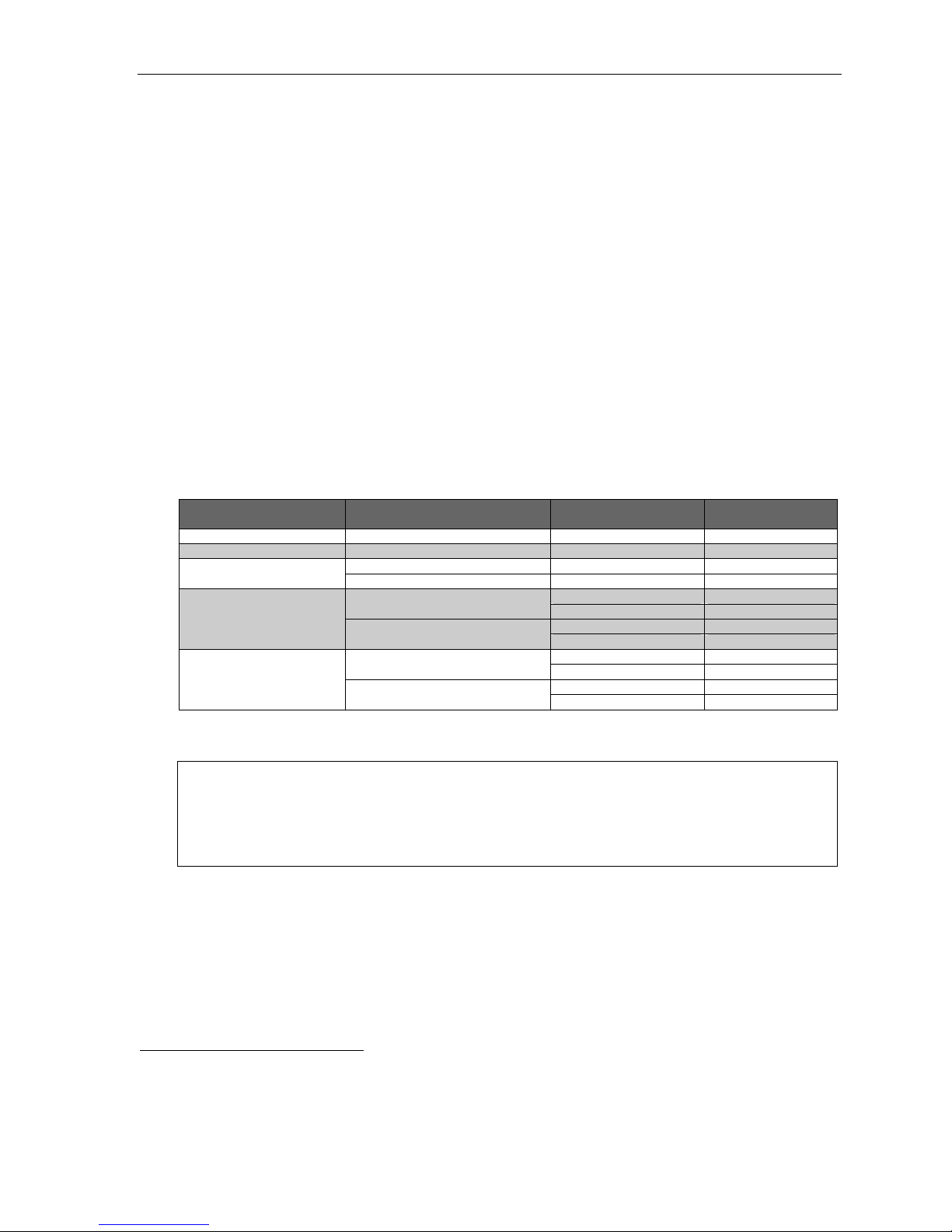
Stations and trunks
The spe cific ations shown below reflect maximum capacities and configur ations. Not all of the station a nd trunk
maximums c an be r ea ched si mul t an e ousl y.
Maximum modules 8 8
Maximum port configuration1 500 400
– Maximum stations 191 168
– Maximum IP stations 127 127
– Maximum digital stations 64 64
– Maximum analog stations 32 32
Maximum CO lines 192 84
Maximum T1/PRI Modules 2 2
Esi-Link channels 127 127
SIP trunking capability (Built-in) (Built-in)
Maximum number of SIP trunks 127 84
Maximum lines available 192 84
Diali n g pla ns ( -d ig its)
Dedicated ports
Voice mail/auto attendant ports 32 32
Conference po rts (max. of 16 members
per conference)
NSP2 1 1
Overhead paging ports 1 1
Serial/SMDR port s n/a n/a
Meet-Me Conference Bridge s 4 4
Diali n g pla ns ( -d ig its)
Four Three
Four Three
64 64
Voice mail capacities
Voice mail storage (hours) 140 140
Broadcast mailbox (one to all extensions) Yes Yes
Cascade notification mailboxes 20 10
Group mailboxes/max. members 32/64 32/64
Guest/info mailboxes 1,000 190
Maxim um station mai lboxes 191 168
Q & A mailboxes 20 10
Maximum unheard messages per mail box 128 128
Maximum stored messages per mailbox 256 256
Find-Me stored phone number s 1,000 1,000
1
Includes Esi-Link channels.
2
Network Services Processor; see the IP Server 900 Hardware Installa tion Manual (ESI # 0450-1305).
Diali n g pla ns ( -d ig its)
Four Three
B.1
Page 10
IP Server 900 Programming Manual System capacities
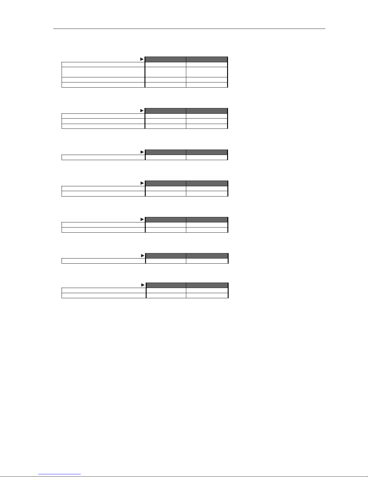
Departments
Max. departments 64 20
Department types: Rin g-all, ACD, UCD, inorder, pick-up, attendant
Max. members, non-ring-all depts. 64 64
Max members, ring-all depts. 64 64
Diali n g pla ns ( -d ig its)
Four Three
Yes Yes
Automatic call distribution (ACD)
Max. ACD departments 64 20
Max ACD agents per department 64 64
Max ACD agents (system-wide) 191 168
Diali n g pla ns ( -d ig its)
Four Three
Shared-office tenanting
Tenants 8 8
Diali n g pla ns ( -d ig its)
Four Three
CO line groups
Line groups 9, 8, 71–76 Yes Yes
Max. members, CO ring assignment l ist 64 64
Diali n g pla ns ( -d ig its)
Four Three
Translation tables
Pilot numbers 100 100
Max. DID entries 600 600
Diali n g pla ns ( -d ig its)
Four Three
System speed-dial numbers
System speed-dial numbers 1,000 100
Diali n g pla ns ( -d ig its)
Four Three
Maximum installations of VIP 7 applications
Installations, VIP 7 PC Attendant Console 8 8
Installations, VIP 7 ACD Supervisor 8 8
Diali n g pla ns ( -d ig its)
Four Three
B.2
Page 11
IP Server 900 Programming Manual System capacities
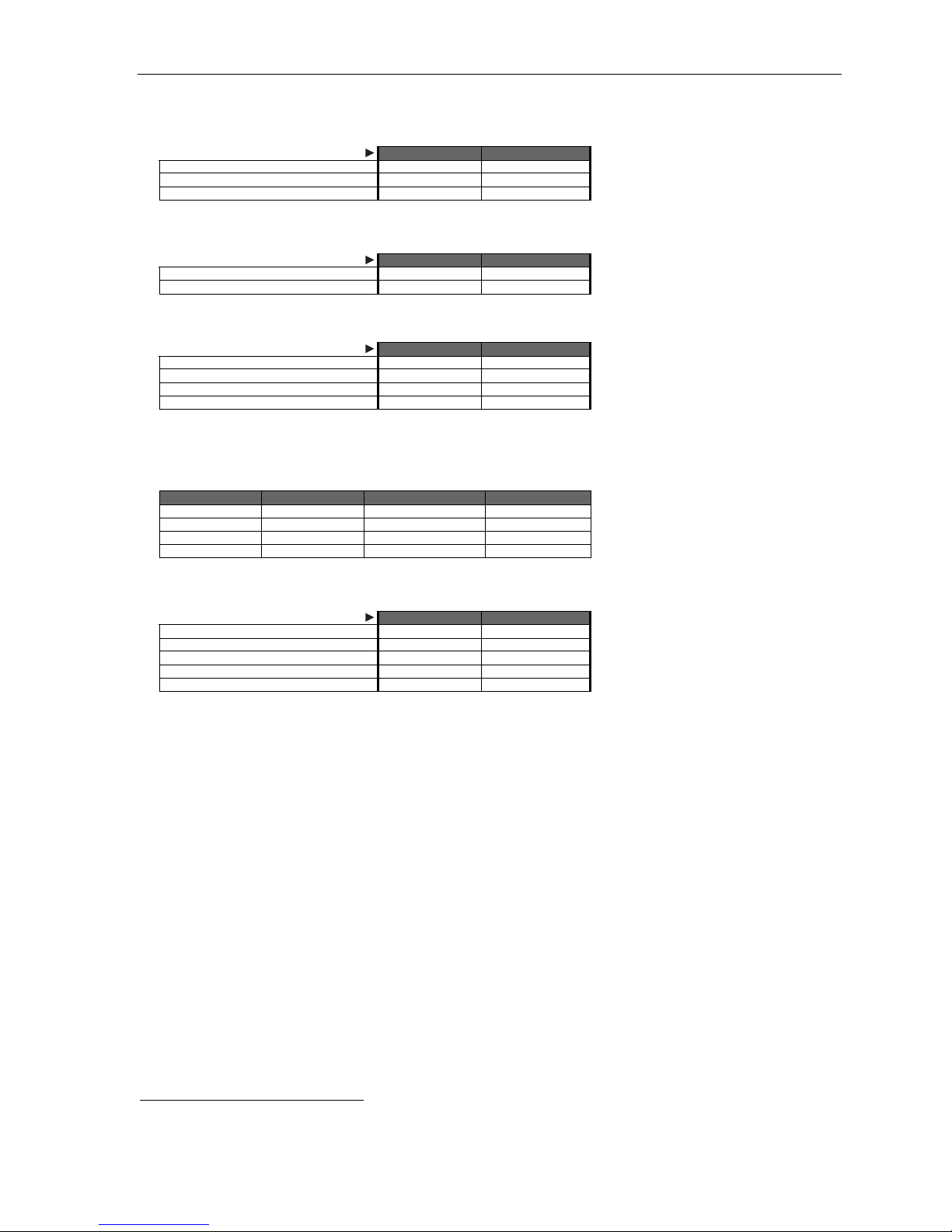
ESI Presence Management features
RFID Reader access door records 10,000 10,000
RFID Reader entries in Fn. 3721 32 32
Max. RFID tags (“electronic keys”) 500 500
Diali n g pla ns ( -d ig its)
Four Three
ESI Mobile Messaging features
Maximum stations 191 168
Maximum guest mailboxes 250 250
Diali n g pla ns ( -d ig its)
Four Three
ESI Video Viewer and ESI Video Adapters
ESI Video Adapters (see below) 12 12
RFID Readers per ESI Video Adapter 1 1
User extns./depts. per ESI Video Adapter 64 64
ESI Video Viewer users 20 20
Although the system supports up to 12 cameras, a variety of other factor s can affect the maximum numbe r of usable camera s. The frequency and
duration of video recordings from each camera as well as overall network load to the system — such as local or remote IP phones, SIP trunks,
SIP stations, and usage of ESI application s (e.g., ESI Mobile Messaging, VIP 7, or ESI Presence Management) — can severely impact the
performance of both the cameras and the IP Server 900. The following chart can be used as a general guideline for determining the number of
cameras supported based on system configuration and usage:
Number of users Li gh t us a ge Medium usage Heavy usage
20 12 cameras 12 cameras 10 cameras
40 12 cameras 10 cameras 8 came ras
60 10 cameras 8 cameras 5 cameras
120 8 cameras 6 cameras 4 cameras
Diali n g pla ns ( -d ig its)
Four Three
ESI Media Management features
Video recordings 12 12
Audio recordings 32 32
SMDR events Yes Yes
Fob activity Yes Yes
ESI Media Manage r user s 20 20
Diali n g pla ns ( -d ig its)
Four Three
1
See the ESI Presence Management Installation Manual (ESI document # 0450-0792).
B.3
Page 12

IP Server 900 Programming Manual System programming: An introducti on
Syste m pr og r a m mi n g: An intr od u ct io n
You can program an IP Server 900 either (a.) from an ESI desktop phone1 in the system or (b.) with IP Server 900
Web ESI System Pro gr am mer. Both me thods follow the same prog rammin g steps. This manual focuses on
programming from an ESI desktop phone; for more information on local or remote administration through the
Web programming interface, consult the IP Server 900 Web E SI System Programming Manual (ESI document
# 0450-1366).
Read the User’s Guide first. Pr ogr amming feat ur es r equi r es a cl ear u nd er st an di ng of th e users’ interface,
features, and applications.
Once you’ve accessed programming mode on an ESI desktop phone, the system will prompt for — and confirm
— each keystro ke action via voice commands and the display. You program both configuration data and
recordings in the same manner.
Important: During programming, the ESI 30D’s two-line display shares the same content as the top two lines of the
If installing ESI Presence Management on this system, refer to the ESI Presence Management Installation
three-line display found on most current ESI desktop phones. As a result, to save space, the sample
displays shown herein will show only two lines.
Manual (ESI document # 0450-0792) for important information before you program the system.
Programming keys
During programming, the first line of the display will show the current item being programmed, and the second line
will be the entry lin e. You ca n enter values as directed by the combinati on of the voice prompts and display.
To enter multiple values, such as a list of extension numbers, separate each value by # (to exit the list, enter # #).
To... Press ... What this does
Enter # Confirms new or existing entry and advances to next
Back up (i.e., reverse direction)
Delete HOLD Deletes data or recording.
Exit [Hang up] Exits programming mode and removes extension from DND.
Help HELP Provides more detailed instructions during programming.
Select/scroll
(right-side scroll key)
(lef t-sid e scroll key)
Notes: Either < or > in the display indicates that additional choices or values are available by pressing a
corresponding scroll key (or ).
programming step.
Backs up to previous prompt without changing its value.
• During entry of a value, backs up.
• If a list is present (“>” is displayed), scrolls to left.
• Selects from options presented.
• If a list is present (“>” is displayed), scrolls to right.
• Inserts a space during entry of a name.
Only one person at a time can be performi ng Installer or Administrator pr ogrammi ng.
1
ESI system programming cannot be performed using an ESI Cordless Handset.
C.1
Page 13

IP Server 900 Programming Manual System programming: An introducti on
Entering alphanumeric characters
You enter names for extensions, departments, branch IDs, CO lines, guest mailboxes and DIDs by
pressing the dial pad key that corresponds to the character to be entered. The key’s possible entries will change
each time the key is pressed, and the display will show this. When the desired character appears on the display,
press # to confirm; the cursor will move to the next character position. You may move the cursor left (to correct
an entry) by pre ssing the left s crol l k ey () or move rig ht (to ad d a spa ce) by pr e ssi n g the right scr oll key ().
Key Options Key Options
0 0, - (hyphen), _ (underline) 7 P, R, S, p, r, s, 7
1 Q, Z, q, z, 1, “_” (space) 8 T, U, V, t, u, v, 8
2 A, B, C, a, b, c, 2 9 W, X, Y, w, x, y, 9
3 D, E, F, d, e, f, 3 (left scroll key) Backs up and erases
4 G, H, I, g, h, i, 4 (right scroll key) Adds a space
5 J, K, L, j, k, l, 5 # [Enter]
6 M, N, O, m, n, o, 6 # # Ends the name
Important: Lower-case letters are available only for programming the settings for Function 2142 (p. E.18) and
Example: To enter a B, press 2 twice (the possible options to scroll through are A, B, C, a, b, c, and 2). When B appears,
Note: On an incoming call, the name you assigned to the call’s CO line or DID — rather than the Caller ID data —
Function 823 (page L.7).
press # to confi rm ; the cur so r wi ll move to th e ne xt c ha rac te r to be ente red . To com ple te the name , pre ss # #.
will appear until the call is answered.
Selectable numbering plan
The IP Server 900’s selectable numbering plan offers up to nine pre-configured ranges — three three-digit plans
and six four-digit plans. When an extension range is selected, department numbers and guest mailbox numbers
are also changed. How ever, regardless of which extension range i s selected, feature k ey code s, and CO line
group access numbers will st ay the same. The dial plan range is selected through Instal ler pr ogramming
Function 169 (see page D.11 for more information).
Notes: The ESI Presence Management RFID Reader1 uses one digital or IP extension, regardless of dial plan.
An ESI desktop IP phone, the IP Cordless Handset (Local or Remote), VIP 7 Softphone, and a SIP phone
Important: Full capacity on the IP Server 900 can be achieved only by using a four-digit plan. (See “System
each uses one IP port, regardless of dial plan.
capacities,” page B.1.)
Line groups
The numbers 9, 8, and 71–76 are desi gn at ed as li ne gr oup s. A line group is, as th e name implies, a specific
group of line s in a key system that are used for maki ng outgoing calls. In an IP Server 900, line groups give
phones access to outside lines without t aking up any pro g rammable key s on each phone.
Note: Line groups 71–76 may conflict with Esi-Link locations 710–769 (if they’re needed); refer to Function 164
1
For more information, see the ESI Presence Management Installation Manual (ESI # 0450-0792).
(see page D.7).
C.2
Page 14

IP Server 900 Programming Manual System programming: An introducti on
Three-digit selectable numbering plan templates for the IP Ser ver 900
Selection 100 (default) Selection 200 Selection 300
From To Used for From To Used for From To Used for
100 267 Extensions 200 367 Extensions 300 467 Extensions
280 299 Departments 380 399 Departments 470 489 Departments
300 489 Guest/info mboxes 100 199 Guest/info mboxes 100 289 Guest/info mboxes
270 273 Conference b ridge 400 489 Guest/info mboxes 290 293 Conference b ridge
370 373 Conference b ridge
Commo n t o a ll three- digit numbering plan se lections f or the IP Serv e r 9 0 0
From To Used for From To Used for From To Used for
0 — Operator #500 #599 Feature key codes 8 — CO line grp.
490 499 Q & A mailboxes 600 699 System speed-dial 9 — CO line grp./ARS
500 — Broadcast mail box 700 709 Esi-Link1 locations
501 532 Group mboxes 770 799 Esi-Link locations # — Paging
533 542 Cascade notif. mboxes 71 76 Esi-Link/CO line grps.
Four-digit number ing plan selection for the I P S erver 900
Selection 1000 Selection 2000 Selecti on 3000
From To Used for From To Used for From To Used for
1000 1863 Extensions 2000 2863 Extensions 3000 3863 Extensions
1864 1927 Departments 2864 2927 Departments 3864 3927 Departments
3000 3999 Guest/info mboxes 3000 3999 Guest/info mboxes 2000 2999 Guest/info mboxes
4000 — Broadcast mail box 4000 — Broadcast mailbox 4000 — Broadcast mailbox
4001 4032 Group mboxes 4001 4032 Group mboxes 4001 4032 Group mboxes
4040 4059 Q & A mboxes 4040 4059 Q & A mboxes 4040 4059 Q & A mboxes
4060 4079 Cascade notif. mboxes 4060 4079 Cascade notif. mboxes 4060 4079 Cascade notif. mboxes
4080 4083 Conference b ridge 4080 4083 Conference b ridge 4080 4083 Conference b ridge
6000 6999 System speed-dial 6000 6999 System speed-dial 6000 6999 System speed-dial
— Call pickup
Selection 4000 Selection 5000 Selecti on 6000
From To Used for From To Used for From To Used for
4000 4863 Extensions 5000 5863 Extensions 6000 6863 Extensions
4864 4927 Departments 5864 5927 Departments 6864 6927 Departments
3000 3999 Guest/info mboxes 3000 3999 Guest/info mboxes 3000 3999 Guest/info mboxes
2000 — Broadcast mail box 4000 — Broadcast mailbox 4000 — Broadcast mailbox
2001 2032 Group mboxes 4001 4032 Group mboxes 4001 4032 Group mboxes
2040 2059 Q & A mboxes 4040 4059 Q & A mboxes 4040 4059 Q & A mboxes
2060 2079 Cascade notif. mboxes 4060 4079 Cascade notif. mboxes 4060 4079 Cascade notif. mboxes
2080 2083 Conference b ridge 4080 4083 Conference bridge 4080 4083 Conference b ridge
6000 6999 System speed-dial 6000 6999 System speed-dial 2000 2999 System speed-dial
Common to all four-digit numbering plan selections for the IP Server 900
From To Used for From To Used for From To Used for
0 — Operator 770 799 Esi-Link locations 9 — CO line grp./ARS
#500 #599 Feature key codes 71 76 CO line grps. or
1
See “Function 8: IP programming” (page L.1).
700 709 Esi-Link locations 8 — CO line grp. # — Paging
Esi-Link loc. prefixes
— Call pickup
C.3
Page 15

IP Server 900 Programming Manual System programming: An introducti on
System programming overview
1 System function programming
11 System Initialization
12 Installer password
13 Administrator password
14 System clo c k and c a le nd ar
141 Set time/date
142 Automatic time setting
143 Clock adjustment
15 System timing parameters
151 Flash hook duration
152 Transfer recall timer
153 Hold recall timers
1531 Exclusive hold recall timer
1532 Hold recall timer
1533 Hold recall timeout timer
154 ACD timers
1541 ACD exit timer
1542 ACD wrap timer
1543 ACD agent hold recall timer
155 SIP stat i on ti mer s
1551 SIP station registration timer
156 Cell phone delay
157 Devic e time r s
158 VIP 7 Attendant exit timer
16 System feature parameters
161 Recording alert tone
162 Connect tone
163 Stat ion fe at ur e para meters
164 Esi-Li n k an d li ne grou p access cod e s
165 Auto at te nd an t par am et ers
166 CO para me ter s
167 Voice mail parameters
169 System feature activation and dial plan selection
17 System spee d- d i al
18 SMDR settings
2 CO line programming
21 Line programming
211 Analog CO line programming
212 T1 programming
2121 Line programming
2122 Frame format and l ine co d in g
2123 Line co mp en s at i on programming
2124 CSU emulation programming
213 PRI programming
2131 Line programming
2132 Line co mp en s at i on programming
2133 CSU emulation programming
2134 Switc h pro tocol
2135 DID
214 SIP trunk programming
2141 SIP tr un k pr ogr am m in g
2142 SIP ac count progr am min g
2145 SIP DID
22 Toll restriction, ARS, and DID programming
221 Line ac ce ss co de pr ogramming
222 Toll table restriction exception tables programming
223 ARS (Automatic Route Selection)
224 DID and DNI S tr an sla t io n ta b le
225 PRI pilo t nu mb er pr ogramming
226 Local allow table
23 Line parameter programming
231 CO Line receive vol um e pro grammin g
232 Open loop prog ramming
233 T1 line receive volume
234 PRI line receive volume
235 SIP trunking line receive volume
24 Caller ID programming
3 Station programming
31 Extens ion de finitio n an d rou ti n g
32 Extens ion fe ature auth or iz at i on
321 Basic feature authorization
322 Advan ce d fe at ure authorization
33 Department groups
331 Department definition and routing
332 VIP 7 ACD parameters
3321 Assign VIP 7 ACD database owner
3322 Manually clear V I P 7 ACD real-time statistics
3323 Set an automatic time to clear VIP 7 ACD real-time stati stics
3324 Set VIP 7 ACD service level threshold
3 Station programming (continued)
34 Reassign an extension, mai lbox, or department number
341 Flexib l e nu mb er a ss ig nm en t
342 Network number a ss ig nm en t
35 Extens ion bu tt on mapping
36 View local and re mote IP feature phone parameters
37 ESI devic e programmi ng
371 Schedules for access control
372 RFID tag number pr ogr am m in g
373 View an ex te n s ion or ma i lbo x ta g nu m ber
374 General ESI Presence Management settings
375 ESI Pre sen c e Ma na ge me nt Rea der settings
376 ESI Vid eo Ada pt er programm in g
30 Station move1
4 Auto attendant programming
41 Auto attendant branches
42 Announc e e xt en s ion nu m ber
43 Automatic day/night tables
5 Voice mail programming
51 Maximu m me s sa ge leng th
52 Message purge control
53 Guest/information mailboxes
54 Group mailboxes
55 Message notification options
551 Messag e no t if ic at io n nu m ber s
552 Messag e de l iv er y parameter s
56 Cascade paging mailboxes
57 Q & A mailboxes
58 Message move and delete
6 Recording of prompts
61 Record system prompts
62 Record directory names
63 MOH
631 MOH source
632 Record MOH
633 MOH vol um e
64 Call recording settings
641 CO line recording parameters
6411 Analo g l in e re co rd in g set tings
6412 T1 line recording settings
6413 PRI lin e re cor d in g settings
6414 SIP tr un k re cor d in g set t in g s
642 Extension or department recording parameters
643 Call recording purge parameters
7 Print system reports
71 System reports
711 Syste m pro gr a m report
712 Diagn o sti c re ports
7121 Abnormal call report
7122 PRI status report
7123 Alarm history report
7124 PRI diagnostics report
7125 Clear diagnostic error counts and alarms
72 ESI Presence Management access door report
73 ACD department statistics report
74 Voice ma il s ta t ist i c s rep ort
75 System spee d- d i al r ep ort
76 NDDS report
8 IP network programming
81 License Management
82 Local IP-PBX programming
821 IP Carrier Card Program settings
822 DSP IP Ad dre s s sett in g s
823 Syst em- W id e I P sett i ng s
824 Network Services Processor IP addressing
825 Soft war e Ma i nt en an c e IP Addr e s s
83 Esi-Link programming
831 Local l o cati on nu mb er
832 Adding an E s i-L ink location
833 Delet ing an E s i-L i n k loc at ion
834 Programming Esi-Link publish
835 Other Esi-Link parameters
84 SIP trun k pr ogr am m in g
86 Unified Messaging selection
87 Universal IP resource programming
871 ESI IP st at io n a llo c at ion
872 SIP stat i on allo c at i on
873 SIP trunk allocation
874 Esi-Li n k tru n k a llo c at ion
1
Shown in the same order as it appears in the p rogramming menu on an ESI desktop phone.
C.4
Page 16

IP Server 900 Programming Manual System programming: An introducti on
Entering programming mode
You may program from any ESI de sktop phone in t he system:
1. Press PROG/HELP at any station. The normal station programming menu prompts will begin to play.
2. Press HOLD. The “enter password” prompt will play.
1
3. Enter the Installer password (default is 7 8 9).
seconds. You are now in programming mode. The extension will be automatically placed in DND, and
its display will show:
INSTALLER
CMD:
4. The system will play the system programming menu. Follow i t to pr ogram as you wish.
5. When finished, hang up.
Then, to confirm the pa ssword, either press # or wait t w o
Warning: Always FINISH programming in ANY function BEFORE exiting programming mode (as needed, press # to
Note: The system will automatically exit programming mode after 10 minutes of inactivity.
Example: If your Installer password is 864, enter programming mode by pressing PROG/HELP HOLD 8 6 4 #.
accept current entries for function parameters you’re not changing).
(To exit programming mode, hang up.)
1
If you prefer to enter Administrator programming mode, use the Administrator password, instead (the default is 4 5 6 ).
C.5
Page 17

IP Server 900 Programming Manual Function 1: System function programming
Function 1: System function programming
Function 11: System Initialization
This function will return all components and software to their initial state. Initialization will erase all data and
custo m recordings — but not the time, date, licensing, or dial plan
Important: Always initialize the system before initial programming for a new installation.
You must confirm the command to initialize, when prompted, by entering the Installer password (and then
pressing # to finish confirmation).
Be sure to set the time and date (Function 14) before initializing.
System initialization will take several minutes to complete. When completed, the phone’s display will return to the
idle state. You must then re-access Programming Mode by following the steps described earlier (see page C.5).
1
(see Important notes, below).
Functions 12 and 13 : Insta l ler and Admi nist rato r pas swords
These functions will display the existing password and prompt for entry of a new password. The passwords can
be 2–8 digits l ong, fol lowed by #. The Installer can ch ange either the I nstall er or Administrator Password.
Only t hose func tions listed in the Administrator Manual can be programme d via the Administrator
Password. The default passw ords are:
Installer Password (Function 12) = 7 8 9
Administrator Password (Function 13) = 4 5 6
Note: Be sure to write down the new passwords, store them in a safe place, and give the new Administrator’s
Accessing user station programming
Should a user forget his password or if an em ployee leaves the organization, this feature allows the Installer
or Administr ator to enter a user's station programming and operate within it as if he were the user. Fr om the
user’s station, enter the Installer or Administrator password when the system prompts for the user password.
Password to the system Ad ministrator.
Example: From station 105, entering 7 8 9 # or 4 5 6 # instead of the user password (1 0 5 #) will enter the station’s
1
Dial plan is set in Function 169 (see page D.11).
user programming. (Default passwords shown for this example).
D.1
Page 18

IP Server 900 Programming Manual Function 1: System function programming
Function 14: System clock and calendar
Function 141: Set time/date
1. Enter a new ti m e in a twelve-hour format.
Example: Enter 1 2 3 3 for 12:33, or 3 1 5 for 3:15 (note that you need no leading zero for the time).
2. Select AM or PM by pressing a scroll key (either or ).
3. Enter a new date in an eight-digit format, including leading zeroes.
Example: Enter 0 7 0 4 2 0 1 1 for July 4, 2011 (n ote tha t lea din g zeroe s are required here, unlike in Step 1).
4. Press a scroll key (either or ) to select the time zone in which this system is located.
Default: Central (CST).
Choices: Hawaii (HST), Alaska (AST), Pacific (PST), Mountain (MST), Central (CST), Eastern (EST).
5. Press # to finish the entry.
Note: A built-in battery maintains the correct time and date, even in the event of a power loss.
Function 142: Automatic time setting
1: Synchronize wi th Caller I D1
This function, when enabled, synchronizes the real-time clock with Caller ID (CID) messaging: call
processing compare s the time of a CID message to the s ystem r eal-time clock and, if the differenc e is
more than two minutes, resets the real-time clock to matc h the time (minutes) of the CID message. The
system will analyze each such message (or — if it receives more than four calls with CID information
withi n a one-minute per io d — as is ne ed ed). Sel e ct ENABLE or DISABLE by pressing a scrol l ke y (either
or ). Choosing ENABLE will allow the CID data to update the time and date.
Default: Disabled.
Esi-Link-related notes (see also “Function 83: Esi-Link programming,” pages L.10–L.11):
(Continued)
If “synchronize with Caller ID” is enabled, Esi-Link time synchronization (from location 700)
will be disabled.
If “synchr onize w ith Calle r ID” i s disabl ed, Esi-L in k time sync hroni zat io n will be allo wed (m inute s onl y).
When Esi-Link is used, all cabinets’ time will be synchronized by cabinet 700, unless “synchronize
with Caller ID” is enabled in Function 142.
1
Does not work with PRI.
D.2
Page 19

IP Server 900 Programming Manual Function 1: System function programming
2: Adjust for Daylight Saving Time
This function, when enabled, causes the real-time clock to adjust itself automatically for Daylight Saving
Time (DST). Select AUTO or DISABLE for DST by pre s sin g a scr oll ke y (eit h er or ). Choosing
DISABLE is best for those areas that don’t ob serve DST.
Default: Disabled.
Note: If this function is enabled and it causes an automatic time change, the system won’t update the real-
time clock from either Caller ID messages (Function 1421, above) or Esi-Link time synchronization
for 25 hours before and 25 hours after the time change is due to be effective (i.e., 2:00 AM Sunday).
Function 143: Clock adjustm ent
This function lets the Installer or Admi nistrator ha ve the system automatically compens a te for a clock that’s
running too fast or t oo slow. The clock adjustment speeds up or slows do wn the clock over a 30- day period by
the amo unt selected. I f the system clock is runni n g slow, select a positive value. If the clock is running fast,
select a negative value.
Range: -2 to +5.5 minutes. Default: 0.
Example: If the clock is running two minutes fast over a month, select -2 (minus two minutes).
D.3
Page 20

IP Server 900 Programming Manual Function 1: System function programming
Function 15: System timing parameters
Function 151: Flash hook dur ation
This sets the time (in seconds) that a flash hook will be sent on the current line to the Telco from a digital
phone s et. The default setti ng of 1.5 will cause disconnect and fresh dial tone from the CO.
Range: 0. 2– 2.0. Default: 1.5.
Function 152: Transfer recall tim er
This sets the n umber of times a transf erred or DID1 call will ring before following the day/night routing for the
extension or depar tm ent .
Range: 1–9 rings. Default: 3.
Function 153: Hold recall timers
Function 1531: Exclusive hold recall timer
This is the amount of time, in seconds, that a call will remain on exclusive hold or loop-key hold before
recall ing to t he extension that initiate d the exclusive hold or l oop-k ey hold.
Range: 5–960 seconds. Default: 60.
Function 1532: Hold recall timer
This is the amount of time, in seconds, that a call will remain on hold before recalling to the extension that
initiated the hold.
Range: 5–960 seconds. Default: 60.
Function 1533: Hold recall timeout timer
This is the number of times a station will recall-ring before being re-routed.
Range: 2–40 rings. Default: 6.
Function 154: ACD timers
Function 1541: ACD exit timer
This is the amount of time, in seconds, that a call will remain in ACD department queues before following
the depart m e nt rer oute (see Fun cti o n 33, pa ge F.2 8) .
Range: 5–6 00 s ec on ds (or 0 for no lim i t) . Default: 180.
Function 1542: ACD wrap timer
This is the maximum amount of time, in seconds, that an agent can remain in wrap mode. If this function is
turned off, agents cannot place their stations in Wrap Mode (see the “ACD agent operation” chapter in the
User’s Gui de).
Range: 5–600 seconds (0 for no limit). Default: 0 (no l imit).
Function 1543: ACD agent hold recall timer
This is the amount of time, in seconds, that a call will remain on hold by a logged-in ACD agent before
recall . (A logged-out user will follow the Function 1532 timer when placing someone on hold.)
Range: 5–960 s econds. Default : 60.
1
Direct Inward Dialing.
D.4
Page 21

IP Server 900 Programming Manual Function 1: System function programming
Function 155: SIP station tim ers
Function 1551: SIP station registration timer
Becaus e the system ca nnot detect wh en a SIP station becomes disconnected, the system requires that
the station p eriodically re- register. This funct ion determines the amount of t ime a SIP stati on regist ration
will last. If this timer expires before a new register request is received the system will consider the phone to
be discon ne ct ed. The value is in seconds.
Range: 5–3600. Default: 1800.
Function 156: Cell phone delay
When one use s a cell ul ar phon e or c ordless phon e to pi ck u p mes s ages, this usuall y re q uir e s the us er to
move the phone away from the ear frequently in order to press command keys, making the user miss some
porti on of th e ne xt pr om pt. This f u nction adds add it io nal d ela y bef or e the playbac k of system prom pts d ur in g
remote message pickup or message pickup from an analog station (this does not affect ESI phone message
pickup). The value is in seconds.
Range: 0. 0– 5.0. Default: 1.0.
Function 157: Device timers
Field 1 : Door unlock relay time r
Used only with ESI Presence Management. This is the number of seconds that a door-unlock relay will
remain open af ter one has pressed a remote d oor-unl ock key.
Range: 2–60 seconds. Default: 4.
Field 2 : Fax s e rver dial del a y
This is the amount of time the system will pause before sending the DID digits to a fax server after the call
has been answered.
Range: 5–100. Default: 50 (500 ms).
Function 158: VIP 7 PC Attendant exit timer
This is the amount of t ime it t akes an Attend department call (see “Department hunting methods,” page F.28)
to enter and exit the Attendant queue.
Range: 5–900 seconds. Default: 180.
Function 16: System feature parameters
Function 161: Recording alert tone
This sets whether the system plays a short beep tone every 15 seconds during a call re cording, indicatin g to
both parties that a recording is in progress.
Default: Disabled (the beep doesn’t play).
Important: IN MOST JURISDICTIONS, IT IS PERMISSI BL E TO RECORD A CONVERSATION IF ONE OF THE
Function 162: Connect tone
TWO PARTIES IS AWARE THAT IT IS BEING RECORDED. HOWEVER, ESI TAKES NO
RESPONSIBILITY AS TO ITS LEGALITY IN ALL JURISDICTI ONS. IT IS THE RESPONSIBILITY OF
THE INSTALLING COMPANY AND THE END USER TO DETERMINE AND FOLLOW T HE
APPLICABLE STATE AND LOCAL LAWS REGARDING RECORDING OF CONVERSATIONS.
This sets whether the system plays a system conne ct tone (two short beeps a user hears when a
stati on a nswers).
Default: Enabled (the beeps play).
D.5
Page 22
IP Server 900 Programming Manual Function 1: System function programming
Function 163: Station featur e par am eter s
Field 1 : Group list e n e na ble/disable
With this feature disabled: if a st ation user pr e s ses SPEAKER while on a call, the ESI phone immediately
turns off the handset and switches to hands-free mode.
If enabled, the grou p liste n featur e is avai lable system-wide. I f disabled, it is no l onger available.
Default: Enabled.
Field 2: Privacy release enable/disable
With this feature enabled: if a station user presses a CO line key that is in use (l it red) , the user wi ll be
immediately conferenced with the call in progress on that line. With this feature disabled: pressing an in-use
CO lin e key has no eff ect.
Default: Disabled.
Warning: Adjusting this parameter while calls are in progress may result in temporary loss of audio.
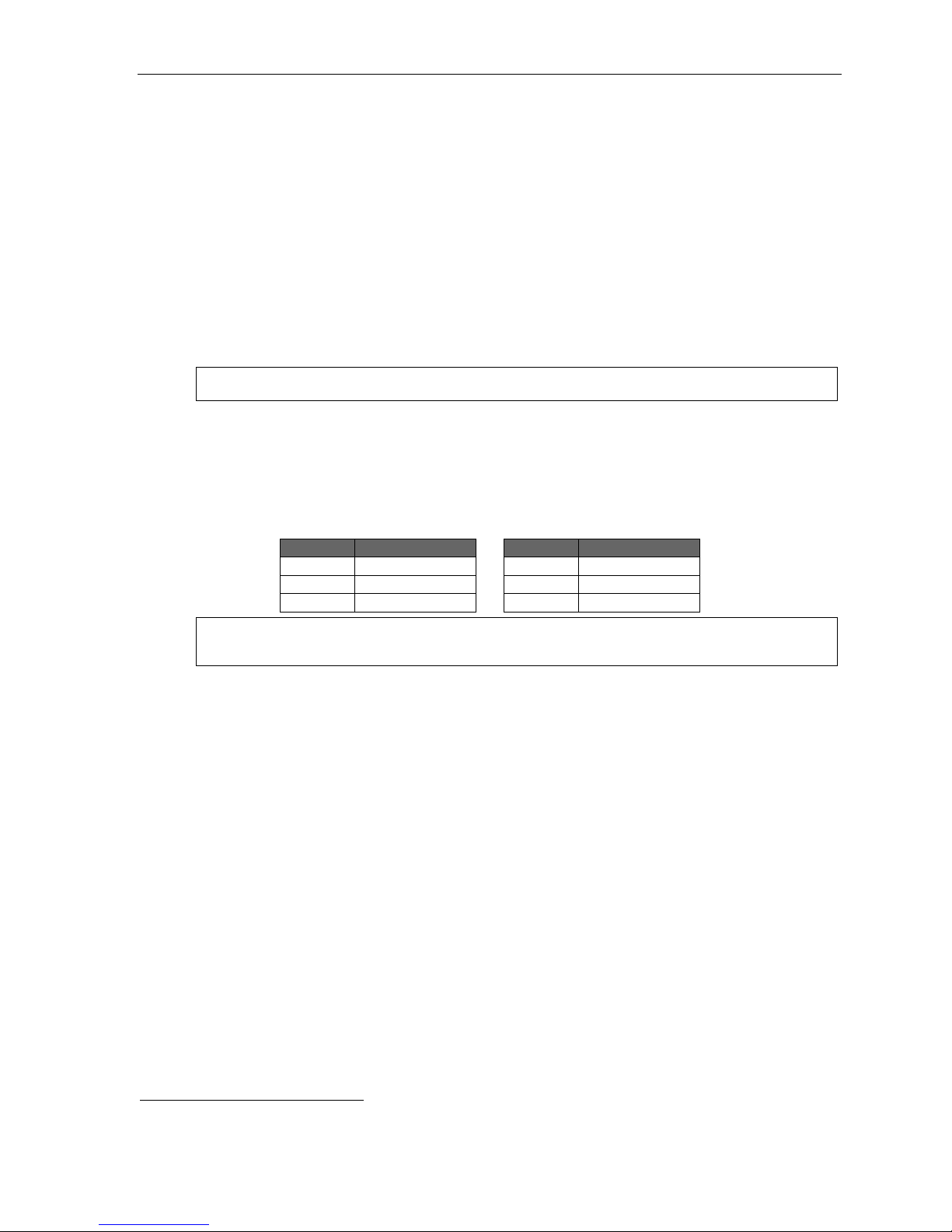
Field 3: Headset microphone gain adjust
Adjusts the gain of headset microphones connected either directly to the headset jack found on most ESI
desktop phones. If the headset microphone gain is too high (“hot”), the user may perceive an annoyingly
loud sidetone or hissing when on a station- to-CO call. T he default lev el should provide a comfortable
sidetone level and adequat e transmit vol ume when used with recom mended headsets.
Range: 0–5. Default: 2. ( See table, below.)
Entry Value Entry Value
5 +9dB 2 0dB (default)
4 +6dB 1 -3dB
3 +3dB 0 -6dB
Warning: Changing the headset microphone gain will drop all calls in progress. Before making any changes to
this parameter, make sure that all stations are idle.
Field 4 : VIP 7 text-messaging enable/disable
With this enabled, us ers of VIP 7 applications1 can use VIP 7 text-me ssa gi n g.
Default: Enabled.
Field 5: System-wide HOLD key lamp appearance
With this feature enabled: when a st ation user pr e sse s th e HOLD key, the HOLD LED flashes on all ESI
digit a l stations in the system whe n the call is pl aced on system-wide hold.
With this feature disabled: wh en a stat i on u ser pre s ses th e HOLD key, the HOLD LED remains off on all
ESI digi tal stations in the system except the station that placed the call on system-wide hold.
Default: Enabled.
Field 6 : Ex c lusive hold a s default
If system-wide is selected: when a station user momentarily presses the HOLD key, the call is placed on
system -wide hold; pre ssi n g th e HOLD key for an extended time period places the call on exclusive hold.
If exclusive is sel ect ed: when a st ation user mom entarily pr e sse s th e HOLD key, the call is placed on
exclusive hold.
Options: Sy st em -wide and excl usive. Def ault : Sy ste m- wi de.
1
VIP 7, VIP 7 ACD Agent, VIP 7 ACD Supervisor, VIP 7 PC Attendant Console, and VIP 7 Softphone.
D.6
Page 23
IP Server 900 Programming Manual Function 1: System function programming
Function 164: Esi-Link and line gr oup acces s codes
Without Esi -L i nk in st al le d, li ne gr o up a cce ss co d es 71 –76
aren’t reser ved for a particular purpose.
1
But, with Esi-Link
installed, these codes are automatically reserved for
Esi-Li nk location access, a s shown in the chart at right.
However , even if Esi-Link is installed, the Instal ler can
manually change codes 71–76 using Function 164.
Once t hese codes are manually change d, the Esi-Lin k
locati on num b er s begi n ni ng wit h t he same t wo di gi ts ca n no
longer be u se d (e.g., if line ac ces s co de 7 1 is cha ng ed for
non-E si-Lin k use, Esi-Link locati on numbers 710–719 are no
Numbering of locations or line groups
Esi-Link location
number range (default)
710–719 71
720–729 72
730–739 73
740–749 74
750–759 75
760–769 76
Line group access
(if selected)
longer av ailable) .
Function 165: Auto attenda nt par am eter s
Field 1 : Auto a t t e ndant inte r-digit tim e r
Make t his sett ing higher if caller s complain that they don’t hav e enough time to dial before either t he
system sends them to the wrong destination or they hear “Your entr y was not valid”; make it lower i f they
say it pauses too long after they dial digits. This sets the time after the first digi ts has been entered and
before the entered number is accept ed as being complete (ti me betw een each digit dialed). Expressed in
1/100 s of seconds.
Range: 40–1000 (i.e., 400 ms to 10 seconds). Default: 200 (i.e., 2 seconds)
Field 2 : Auto a t t e ndant no-re s ponse timer
Adjust i f the time aft er the playing of the auto attendant greeting is too long (or too short) befor e the system
follows the no-resp onse (call-forward) destination of a menu or directory. Sets aut o attendant’s noresponse timeout time. This is how long the auto attendant waits until after the menu plays all options.
Express e d in 1/1 00 s of se co nds.
Range: 50–6000 (i.e., 50 0 ms to 1 minute). Default: 300 (i.e., 3 seconds).
Field 3 : ACD beep
Enables or disables t he ACD beep tone ( same as the “ne w m essage” beep) given to agents logged into
an ACD de partment when they’re in a bus y condition and a call goes into queue.
Range: 0 (enabled) or 1 (disa bled). Default: 0 (enabled).
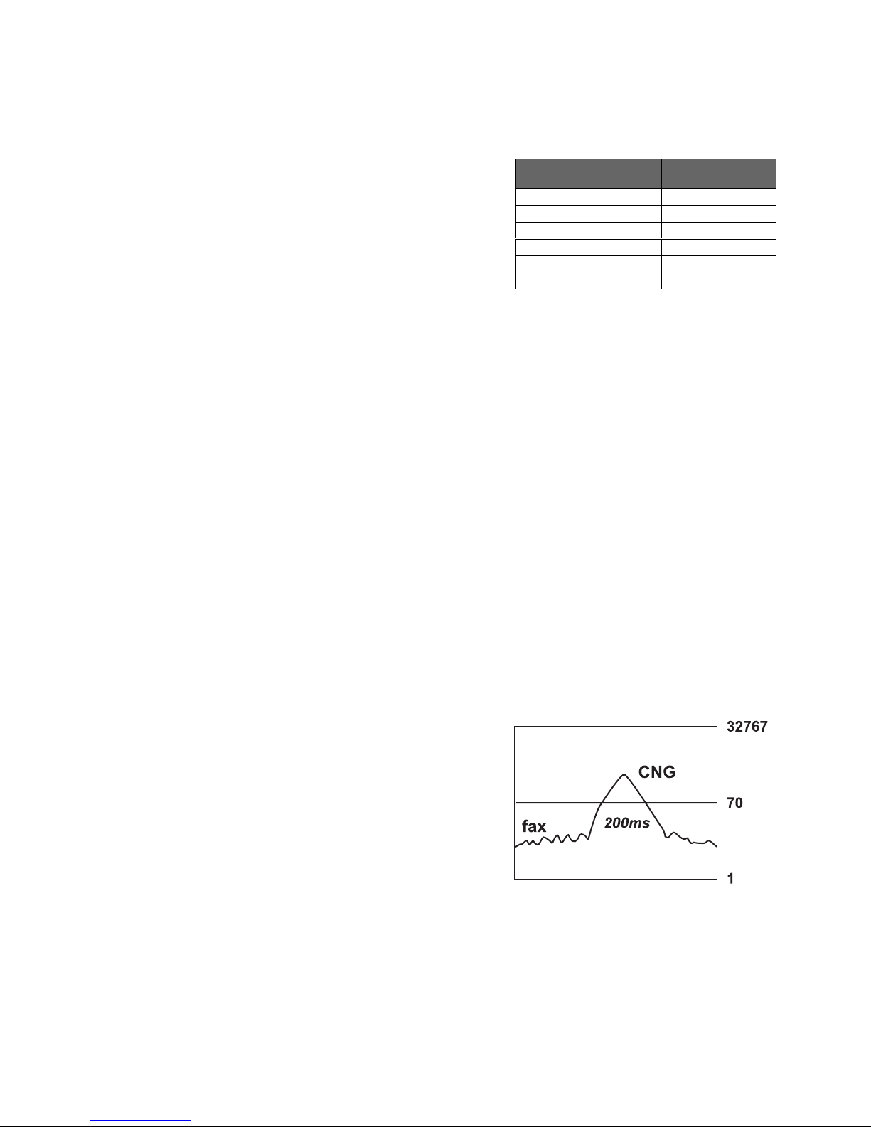
Field 4: Fax energy level (CNG tone)
Adjust this level if fax calls aren’t routing properly when
the auto attendant answers. Incre a sing (or decre asing)
this field causes the system to look for more (or less)
CNG tone to detect whether it’s a valid tone. This is a
threshold le vel, so setting it too low may c ause the system
to route all calls to the fax port. The energy level of a fax
signal must exceed this setting for more than 200 ms.
Range: 1–32767. Default: 70.
Field 5: Name key digits
(Number of digits used for the auto attendant directory
branch name key
prompt an outside caller to enter when in an auto attendant directory branch.
Range: 1–3. Default: 3.
1
I.e., as are line access numbers 9 and 8.
2
See “Function 62: Record directory names,” p. I.2.
2
) This is the number of digits corresponding to the number of letters the system will
D.7
Page 24
IP Server 900 Programming Manual Function 1: System function programming
Function 166: CO parame ters
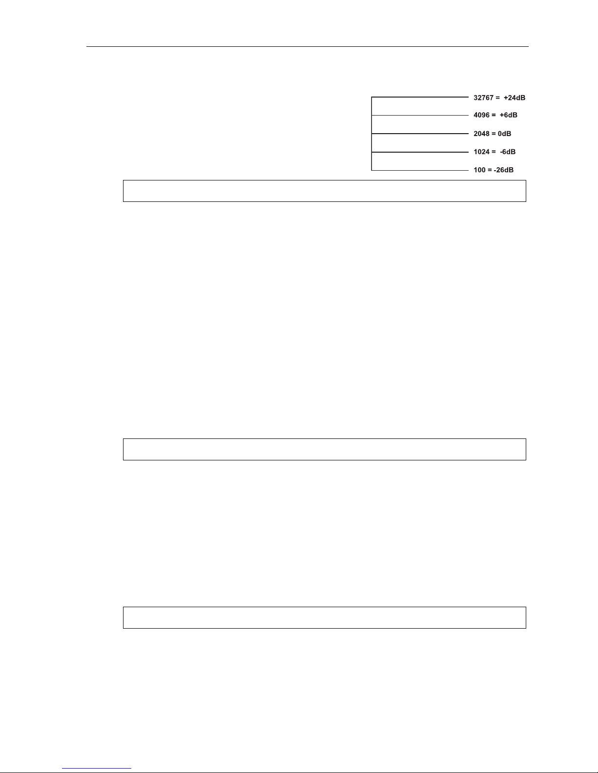
Field 1: CO-to-CO conference gain
Adjusts the volume level on CO lines when in a
conference c all. Increasing this level to a high setting can
cause ex ces si ve noise or fee db ack on c onf er e nc e call s. Thi s i s
a threshold gain lev el. Doubl ing or halving the cur rent setting is
in 6dB increments.
Range: 100–32767. Default: 2048.
Warning: Adjusting field 1 while calls are in progress may result in temporary loss of audio.
Field 2 : ARS inter-digit timer
Adjust this timer if the sy stem disconnects the call bef o re all digits are sent or there is an excessively long
delay before the number is di aled. Sets the time after the first digit has been entered and before the
entered number is accepted as being complete. Thi s is when ARS (see “Funct ion 223: Automatic route
selection [ARS],” page E.28) is enabled and an outgoing call is made. Also controls the amount of time
available for dialing when PRI lines are accesse d. Expressed in 1/100s of secon ds.
Range: 40–1000 (i.e., 400 ms to 10 se con ds) . Default: 50 0 (i.e., 5 seconds).
Field 3: CO playback gain
Adjusts the volume level the system uses to play back recordings, prompts or messages to a CO line. If
this value is set too low, callers i nto the system may not be able to hear th e greeti ng of a m ailbox or the
auto attendant when either a nswers the call . 6 = 0dB; going up or down from t here is i n 3dB increments.
Range: 1–12. Default: 6.
Field 4 : Tr unk- t o- t runk CO gain
Adjust this if call ers in a trunk-to-trunk connection — either through the “r each-me” feature, manual
conne cti on or auto atte ndant — are u na ble t o he ar or ha ve e xces si ve noise or feedb a ck.
10 = 0 dB; going up or down from there is in 3dB increments.
Range: 1–12. Default: 11.
Warning: Adjusting field 4 while calls are in progress may result in temporary loss of audio.
Field 5: Delay before connection “beep-beep”
Adjust this i f connection tones are played either too soon or too late after the system answers a C O or
intercom call. Sets the amount of time before the connection “beep-beep” is started. Expressed in 1/100s
of seconds.
Range: 10–100 (i.e., 1 00 ms to 1 second) . Default: 20 (i.e., 200 ms).
Field 6: Caller ID gain
Adjust this level if Caller ID inf ormation isn’t being displayed. Setting this field tells the system h ow much
CID signal it needs to determine whether the signal is valid CID. This is a value set in the DSP and i s
similar to the fax energy level (se e Function 165, f ield 4, page D. 7).
Range: 1–32767. Default: 2000 0.
Warning: Adjusting field 6 while calls are in progress may result in temporary loss of audio.
(Continued)
D.8
Page 25

IP Server 900 Programming Manual Function 1: System function programming
Field 7 : PRI local numbe r digit l e ngth
Tells t he system whether there is seven- or 10-digit lo cal dial ing in the system’s area. If the local call ing
area uses only seven-digit dialing, set thi s value to 7 (this tells the system not to wait for additional digits
when a local seven-digit number is dialed).
Range: 7 or 10. Default: 10 (supports both 10- and seven-di git dialing).
Field 8 : Di a ling off-hold
Enables or disables outside callers’ ability to dial off-hold only when MOH 590 (external source) is
selected. Wh en this is enabled, CO callers will be able to dial extension, department, and mailbox
number s while on hold. When this is disabled, the system will ignore digits dialed by CO callers. To
enable or disable outside callers’ abil ity to dial off-hold, press a scroll key to make the desired selection
and then press # to confirm.
Default: Enabled.
Field 9 : Re- s ending of Caller ID in Int e lligent Call Forwar ding (PRI)
This parameter “tur ns off” the repeat Call er ID (re-sending) component of Int ellige nt Call F orwarding in
PRI. Some service providers — local exchang e carriers or inter-exchang e carriers — don’t allow repeating
the call er’ s CID d ata wh en ma kin g an out going call.
If re-sending of Caller ID is disabled, the PRI pilot number of the station’s tenant will be sent instead.
If re-sending of Caller ID is enabled, CO calls that are forwarded to an off-premises number over a PRI
channel will send the original caller’s CID data to the called person. To enable or disable this parameter,
press a scr ol l ke y to ma ke th e desi r ed s el ect i on an d th e n pres s # to confirm.
Default: Enabled.
Note: Call forwarding off-premises and call forwarding no-answer/off-premises will be unaffected by
changes to this parameter.
Field 1 0 : Re- s e nding of Cal ler ID in Inte lligent Call Forwardi ng (SIP)
This parameter “turns off” t he repeat Call er ID (r e -sending) component of Intelligent Call Forwarding in SIP
trunki n g. Som e ser v ic e pro vi der s — lo cal ex c ha nge car r i ers or i nter - ex cha ng e car ri er s — don’ t all ow
repeating th e caller’s CID data when ma king an outgoing call.
If re-sending of Caller ID is disabled, the SIP pilot number of the station’s tenant will be sent instead.
If re-sending of Caller ID is enabled, CO calls that are forwarded to an off-premises number over SIP
trunki ng will send the origi nal caller’s CID data to the called person. T o enable or disable this parameter,
press a scr ol l ke y to ma ke th e desi r ed s el e ction and the n pr ess # to confirm.
Default: Enabled.
Note: Call forwarding off-premises and call forwarding no-answer/off-premises will be unaffected by
changes to this parameter.
Field 11: Fax call default destination
This parameter determines where fax calls detected by the system auto attendant will be routed.
If this field is left at the default setting of ANALOG the system will route faxes that are detected by the auto
attendant to the low est-num bered extension in th e system that has a type of Fax in Function 31.
If this field is set to ESI FAX the system will route faxes detected by the auto attendant to the IP Server
900’s bui lt - in Fa x ov er e-m ai l f eat ur e.
Default: ANALOG.
Note: With a setting of ESI FAX the system will send a notification e-mail to the system’s operator extension
with the fax attached as a .PDF file.
D.9
Page 26

IP Server 900 Programming Manual Function 1: System function programming
Function 167: Voice mail param eter s
Field 1: Energy threshold
Adjust this downward if (a.) callers in a mailbox,
on a conference call or in the auto attendant are
being di sc onn ected and/ or (b.) mess ag es i n a
mailbox are incomplete. Adjust this upward if
mailboxes are storing messages with long
periods of silence. This sets the v alue used to
detect energy received by the system on any
port. Lowering this v alue means less energy will
be required to stay connect ed. Energy below this
level is treated as silence.
Range: 0–65535. Default: 500.
Field 2: Recording silence value
This sets how much consecutive sile nce can b e recorded in a mailbox before it stops and plays the “ end of
recording” pr ompt (537). Expressed in 1/1 00s of seconds.
Range: 200–3000 (2 to 30 seconds). Default: 350 (3. 5 seco nd s) .
Field 3 : Pa ge glare detec t ion
Enables or disables t he ignoring of page glare when using pager not ification. When this is set to 1, the
system will go off-hook and send phone or pager strings regardless of dialtone detection. Enable this field
if one or both of the following occur:
• CO lines are not relea sing immediately after a pager notificati on.
• “Phantom” incoming calls ( no caller and no Caller I D ) are occurring.
Range: 0 (disabled) or 1 (ena bled). Default: 0 (disable d).
Field 4: Maximum messages in Recycle Bin
Sets the maxim um number of messages in the Mess age Recy cle Bin.
This is a system-wide setting.
Range: 2–40. Default: 10.
Field 5: Unified messaging playback exit timer
Sets the maxim um duration in seconds to keep the ESI phone connected to voice mail (i.e., wait for
additi onal user entries) after a message stops playing via VIP 7.
Range: 0–20 (seconds). Default: 4.
D.10
Page 27

IP Server 900 Programming Manual Function 1: System function programming
Function 169: System feature activation and dial plan selection
Field 1: Tenant service
Enables/disables t enant service. When tenant ser vice is enabled, stations and departments must b e
assigned to one of eight tenants in Functi ons 21, 31, or 33. Tenant service affects:
• Function 21 (CO line assignment, page E.1)
• Function 225 (pilot number translat ion table, pa ge E.32)
• Function 31 (extension definition and routing, page F.2)
• Function 33 (department programming, page F.28)
• Function 4 (auto att endant programm ing, page G.1)
• Function 63 (MOH programming, page I.3)
Default: Disabled.
WARNING: When tenant service is enabled, ID branches 2 through 8 (see “Auto attendant programming,”
beginning on page G.1) will be initialized for each tenant’s main menu branch.
Field 2 : CO line tenant c he c k
Note: Offered only if tenant service is enabled in Field 1.
Controls two f unctions. If CO line t enant check is enabled:
1. When a CO line is pl aced on hold, the HOLD key LED fla she s onl y on st ations wh ose te n ant
matches that CO line’s tenant.
2. When a station user presses the HOLD key to retr ieve a call, the display show s only the CO lines
on hold whose tenant m atches that station’s tenant.
Default: Disabled.
(Continued)
1
1
If Function 163 , field 5, is enabled. See page D.6.
D.11
Page 28

IP Server 900 Programming Manual Function 1: System function programming
Field 3 : Se lectabl e numbe ring plan t e m plate
Warning: Changes to this parameter will result in system initialization, which will erase all programming, voice
Note: If a three-digit dial plan is used, the IP Server 900’s full capacity cannot be attained (see page
messages, greetings, and recordings. System programming backups that are of a different
numbering plan range than the one selected cannot be restored.
“Selectable numbering plan,” page C.2).
This paramete r allows the i nstall er to select one of nine pre-d e fined r anges of exte nsion num bers (see
“Selectable num bering plan, ” pa g e C.2). Ho we ver, r egar d le ss of whi c h ext en sio n num beri n g ra ng e is
selected, feature codes, and CO line groups access numbers will stay the same. Press a scroll key to
select a new numb er i ng pla n, or pre s s # to continue. If you select a new numbering plan, you will be
prompted to ini tialize the system by entering the Installer password.
Note: Initialization will take several minutes to complete.
Ranges: (See page C.3.) Default: 100.
Field 4 : I n/out DSS lamp
When a station is in off-premises mode1 or th e s t at ion i s se t t o DN D , a n y ot h er st a tion wi t h a pr o g r am m a bl e
feature key set as a DSS key for that station will light the key amber. This parameter controls how the key
appears am ber :
Key’s amber lighting if phone is in this mode. . .
Setting DND Off-premises
Both solid Solid Solid
DND wink Slow blink Solid
Out office wink Solid Slow blink
Use th e scroll keys to select and press # to confirm.
Default: Both solid.
1
For more information, see the ESI Presence Management Installation Manual (ES I # 0450-0792).
D.12
Page 29
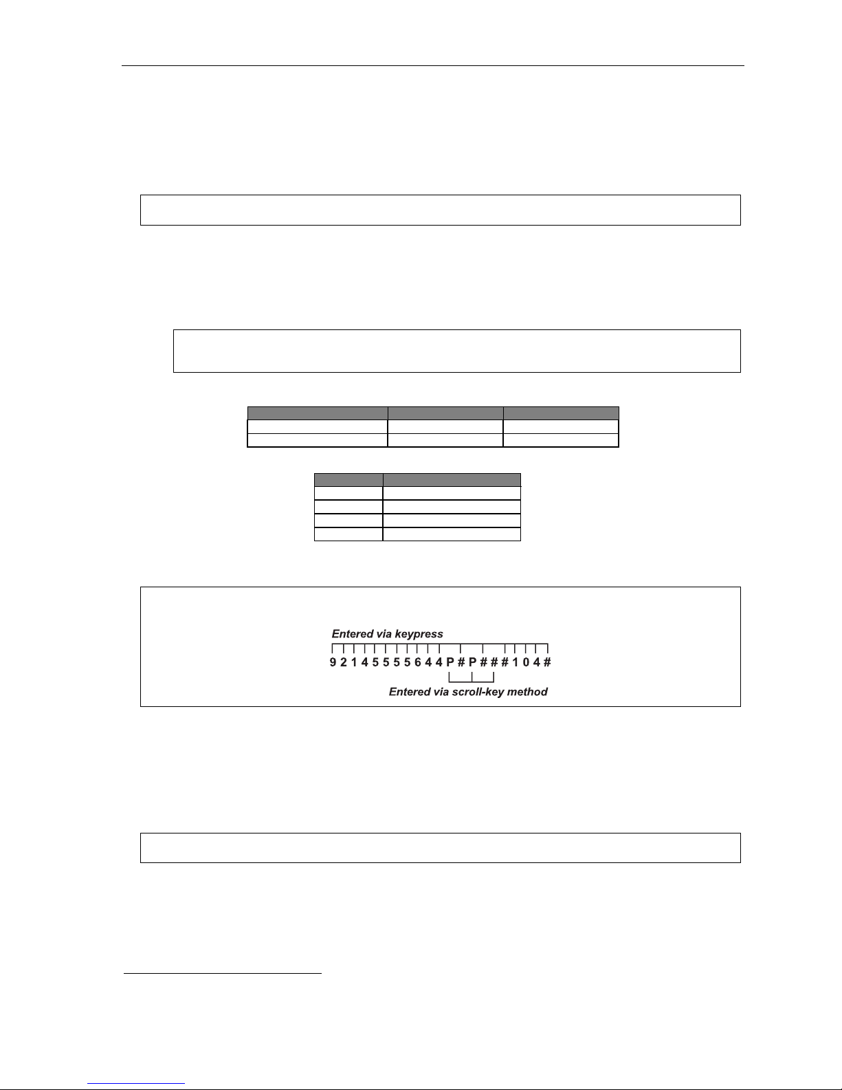
IP Server 900 Programming Manual Function 1: System function programming
Function 17: System speed-dial
Up to 1,0001 system spe ed- di al name s an d as sociated num bers can be stor e d for a cc e ss by any st at i o n.
A user can ini ti at e a syst em spe ed-dial by di aling the spe ed- di al locat i on num b er or by acc es si ng the n ame
throug h th e Esi- D e x feat ur e. In Fun ct io n 32, acce s s to system spee d-d ial ca n be de nie d t o indi vi d ual statio ns
(see page F.23).
Note: System speed-dialing overrides extension toll restrictions (Function 32, page F.23).
1. Enter the three-digit or four -digit sp e ed- di al n umb er to pr o gra m . (For ac ceptable sy stem spe ed-dial
number s, see “Selectable numbering plan,” page C.2.)
2. Enter a name up to 10 characters in length (see “Entering alphanumeric characters,” page C.2).
3. Enter the number to be dialed (including the l ine groups 9, 8, or 71–76). Press t he left s croll k ey () to
delete an y ch ara ct er or digi t e nt er ed i n err or .
Important: When using PRI, don’t enter a pause (“P”) after the line group number. If you do, the system will
send all digits after the pause as DTMF digits, and the call won’t be completed.
Here’ s an e xampl e:
Speed-dial number Name Number
1. 2. 3.
601 AUTO RENTL 915552221212
The number dialed in Ste p 3 can be up to 30 d igits long including special ch ar acters:
Code What it produces
# # DTMF tone
F Flash hook
P 2-second pause
DTMF tone
Use the scroll key to enter special characters; us e the scroll key to ba ckspac e. Press # to confir m the
insert e d char a cter a nd co nti nu e. Pres s # # to complete the entry.
Example: To create a system speed-dial number that dials 9, then 214-555-5644, then pauses for four seconds and
finally dials #104, enter the following dial string:
Deleting a speed-dial number
To delete a n enti r e spe ed-dial num ber and n ame, del et e th e locat i on n umb er by pr e ss in g HOLD or the
left scroll key ( ) during Step 1 i n the speed-dialing procedure described above.
Note: Speed-dial keys can’t be used when the station is already connected to a CO line.
1
Up to 100 if three-digit dial plan is used.
D.13
Page 30

IP Server 900 Programming Manual Function 1: System function programming
Function 18: SMDR settings
Real-time SMDR call re cords are continuousl y output to the IP Ser ver 900’s Ether net port.
Note: Choose STORED in step 1 to have SMDR activity recorded to the ASC’s Memory Module.
1. Select the output device by pressing the scroll keys ( and ):
• NONE (Makin g th is se l e cti on en ds t he pr oc es s at this step. )
• STORED.
• ETHERNET (if connecting to a LAN through an NSP board).
2. Select the SMDR format, STANDARD, EXTENDED, or CSV, by pressing the scroll keys ( and ).
Default: STANDARD.
Note: If STORED was selected in step 1, the SMDR format will be extended and no output will be seen.
Once STORED is selected, the second option (SMDR format) will no longer appear.
Capturing S MDR data ov er E ther ne t
The NSP c an be used to output SMDR data over an IP network; a nd a Telnet connection can be mad e to the
NSP, using port xx003 (default is 59003), to capture th is data. For more information, see NSP Installation
Made Simple (ESI # 0 450-0669).
SMDR output
Examples of SMDR output are shown beginn ing on page K.1.
D.14
Page 31

IP Server 900 Programming Manual Function 2: CO line programming
Funct io n 2 : CO li n e program mi n g
An IP Server 900 can op erate either o n a stati on-by-station basis as a PBX or as a combined key/PBX using
stand ard l o op- star t li n es. If a st at i on ha s li ne ke ys pr o gram m ed , the user ac ce sse s th e li nes by pr e s sin g on e of
these keys or by dialing the line group number 9 (or 8 or 71–76). If a station does not have line keys programmed,
the user always accesses CO lines by dialing 9 (or 8 or 71–76). Since the system handles call transfer and auto
attendant functions efficiently, operating in the PBX m ode pr ovides m ore progr am mable feature keys for other
uses a nd the opportunity for glare i s greatly reduced.
Notes: When a module is added to or removed from the system — i.e., thus cha ngi ng th e num ber and
As a visual indication of CO line usage, the phone’s display will show on/off-hook line status.
All phone programmable keys default to being unprogrammed (except on extension 100, where the first key
Important: Where any gray shading (■) appears in an example, it represents values either unavailable to the function
configuration of modules in the system — you must reprogram the CO lines. However, if a module is
replaced by the same type of module (e.g., when you replace a faulty FXO Module with a new FXO
Module), you don’t have to reprogram the CO lines.
defaults as a day/night key). Use extension button mapping (Function 35; see page F.41) to assign line keys
system-wide. An individual station’s keys can be reassigned using either PROG/HELP 2 or “radio-key
programming” at that station.
or unused in the particular example.
Function 21: Line programming
This function lets you program analog COs (enter 1 to go to Function 211), T1 COs (enter 2 to go to Function 212),
PRI C O s ( e nt er 3 to go to Function 213), or SIP trunks (enter 4 to go to Function 214). To return to the previous
menu, press #.
CO LINE PROG
Important: When you modify the system configuration by changing modules, you must reprogram the CO lines.
Answer ring assignments
Each CO l ine can have up to four programmable answer ring assignment lists. The first list, “Ring 1,” is
used to send incomin g calls on the fi rst ring (or second ring if Caller ID is enabled) to an answer destinat ion.
The “Ring 3” li st is invoked o n the third ri ng, and so on.
Each list can be directed to be answered at up to 64 home loc ation extensi ons, or a department, a mailbox,
the inter nal ESI Fa x ov er e-m ai l server
keys. Destinat ions at a single remote destination (see number ed Notes, page E.3) ca n als o be set as ri n g
assignments in each list.
Ring assignments can be set to add or drop extensions, or add a department, a mailbox, or I D branc h is
ringi ng continues due to no-answer. O nce a de partment, mail box, or ID branch in either a home (local)
location destination or remote location desti nation is encountered in any of the l ists, no oth er ring assignments
will be followed.
The ESI F ax ov er e-m ai l destination tells the system to treat all inbound calls as fax calls. When a fax is
received it will be converted to a PDF file and attached to an email that is sent to the system Operator’s
Mobile Messaging emai l address.
1
The ESI fax over e-mail server requires ESI Mobile Messaging (see “Function 86: ESI Mobile Messaging,” pp E.1) to be enabled and the system
Operator’s Mobile Messaging email address to be set and active (see the IP Server 900 User’s Guide, ESI document # 0450-1306).
2
For more info rmatio n about ID bran ches, see “Func tion 41: Auto atte ndan t bran ch progr amming, ” pp. G.1– G.6.
1
, or an auto att en d ant branch ID2; these can be selected with the scroll
E.1
Page 32

IP Server 900 Programming Manual Function 2: CO line programming
CO ring assignments can include the following Esi-Link
1
remote location destinations:
• Location ID (7xx) + department
• Location ID (7xx) + extension
• Location ID (7xx) + mailbox
Default answer ring a ssignm ent for CO lines: ID1.
• The lines installed via TI can be l oop, ground, E & M, or DID.
• All CO lines are programme d to route callers during the day mod e and then can be programmed to r oute
callers differently during the night mode. The display will indicate D (for day) or N (for night) to show
which m ode is currently being programmed. Lines that are to be programmed alike can be grouped to
simplify progr ammin g.
Programming examples
Here are two examples of how to implement thi s programm ing; each shows a completed progr am m ing
worksheet. Example 1 is simplified, to ser ve as an illust ration for t hose installations not using Esi-Link; while
Exampl e 2 depicts an Esi-Lin k-enabled configuration. In each case, the step numb er s correspon d to t he
explanation in “Function 211: Analog CO line programming,” pp. E.5–E.7.
Example 1 (Simplified; non-Esi -Link )
Incoming calls on Line 1 (default name used, here) ring live to extension 100, but are finally answered
by the main greeting after nine rings.
1 LINE 1 9 X100 X100 X100 ID 1
1.
CO
2.
Name
3.
Tenant
4.
Out
5.
Ring tone
6.
Ring 1 Ring 3 Ring 5 Ring 9
(Continued)
1
For more about Esi-Link, see “Function 83: Esi-Link programming,” pp. L.10–L.11.
E.2
Page 33

IP Server 900 Programming Manual Function 2: CO line programming
Example 2 (with Esi-Link)
CO line 1 answer ring destination
First ring — Line 1 (optionally named “SALES”) rings at operator’s extension.
Third ring — Extension 112 at Location 702 is added.
Fifth ring — Extension 100 and Location 702 extension 112 stop ringing; and Location 703
extension 101 starts ringing.
Ninth ring (or no available Esi-Link channels for Ring 5) — Call is answered by auto attendant.
CO line 2 answer ring destination
First ring — Line 2 (optionally named “MFG.”) rings at extensions 118–119.
Third ring — Line 2 rings at Department 290 in Esi-Link Location 702.
Fifth ring — (In this example, Ring 5 isn’t pr ogrammed. If an Esi-Link connection to Location 702 is
available, the call routing will follow the call forwarding for Department 290.)
CO line 3 answer ring destination
First ring — Line 3 (optionally named “TECH”) is answered by auto attendant (branch ID 4) in home
location. Branch ID 4 is assigned as a GoTo: Remote branch to an ID branch at Location 703.
1.
CO
1 SALES 9 X100 X100
2.
Name
3.
Tenant
4.
Out
5.
Ring tone
6.
Ring 1 Ring 3 Ring 5 Ring 9
X703101 ID 1
1
X702112
2 MFG. 76 X118
3 TECH ID 4
X119
X702290
Notes:
1. If a CO line ring assignment needs to go to a remote location branch ID, see “Function 41: Auto
attendant branch programming” (pp. G.1–G.6).
2. Each CO line ring assignment list can have destination extensions in the home location and in only one
other remote location. You may enter up to 64 extensions, one of which can be a remote location.
3. If the remote location destination is a mailbox or department, no other ring assignments will be followed
(see Example 2, above).
4. Ring assignment list 9 will be allowed to have only home location (local) destinations entered. If all local
channels are busy, the ring assignment to the local destination in Ring 9 will be immediately executed if
there are no other local destinations in the previous ring lists.
5. If a remote location destination is assigned in a ring list and there are no answer ring assignments to
local destinations and there are no Esi-Link channels available to route the call, the call will ring to the
local operator assignment (factory default is X100).
6. Night mode answer ring assignments for remote locations follow the same rules as day programming.
7. Ring assignments will not follow the call forwarding of stations in a ring list that are call forwarded to a
remote location destination.
8. Important: If you’re using VIP 7 PC Attendant Console, you must assign the Attendant department to
answer incoming calls on the preferred ring assignment (ring 1, 3, 5, or 9). Otherwise, incoming calls to the
system won’t appear in the Incoming Calls and Holding Calls windows in VIP 7 PC Attendant Console.
See “Department hunting methods” (page F.28) for information on the “Attend” department type.
1
For more informatio n about ID bra n ches, see “Func tion 41: Auto atte ndan t bran ch programmi ng,” pp. G.1– G.6.
E.3
Page 34

IP Server 900 Programming Manual Function 2: CO line programming
The steps for programmi ng CO lines throughout Function 21 are:
1. Choose the CO l ines to progr am .
2. Name the CO lines. This is optional; to retain the default values — “Line 1,” “Line 2,” and so on —
press #.
Optional naming of the CO lines
During this step, you optionally can name the CO lines you’re programming. Each name can
If you select multiple CO lines to program, the name field will be left blank; at this point, you can
To change an already programmed name to the default value, press HOLD to delete the name
If used in conjunction with Caller ID, this feature causes the Caller ID nam e to a p pe a r on th e first
Default: Line numbers.
contain up to 10 alphanumeric characters. If you press # while performing this step, the default
names (e.g., “Line 1,” “Line 2,” etc.) will be retained.
either press # to keep all of the lines’ default names or, by entering a name, assign the same
name to all selected CO lines.
and then press # while the field is blank. This restores the default values for all selected lines.
line, and the line name to appear on the second line, until the call is answered; then the phone
number will appear for five seconds. After that, a call timer appears on the display. If Caller ID isn’t
enabled, the CO name will appear on the top line of the display. In either case, the third line of the
display (on an ESI phone with a three-line display) shows line usage.
3. Follow t he remaining steps (as described herein) that are specif ic to the function you’re programming —
Function 211 (analog CO line programming), Function 2121 (T1 CO line programming), Funct ion 2131
(PRI CO line pr ogrammi ng), or Function 2141 (S IP trunk progr amm ing).
E.4
Page 35

IP Server 900 Programming Manual Function 2: CO line programming
Function 211: Analog CO line progr am mi ng
This function allows you to program the analog COs for both day and night mode. You can select the trunk
group s and ring assignments for a group of COs or individ ual line s. The steps are:
1. Choose CO lines to program.
2. Name the CO lines (optional).
1
3. Assign the C O lines’ tenant
4. Assign outbound CO l ine groups.
5. Assign distincti ve CO ring tone.
6. Assign answer rings.
1. Choose CO lines to program
During this step, yo u use the programmable keys to represent CO li nes. Select lines to be programmed by
pressing one or more of the programmable keys. Press the scroll k eys ( or ) to “page” in increments
appropriate f or the carrier card configur ation.
keys currently represent.
Software will identify the module type installed in each position. The display will show the card carrier
number, the type of module (FXO), D or N f or day or night mode, and the installed FXO Mod ules or
selected carrier card — A, B, C, or D. The appropriate progr ammable feature key lights wi ll light red to
indicate the lines available to program:
ESI phone Module or
ESI-60 A Left-side 1, 2, 3, 4 48-Key A 1, 2, 4, 5
B Left-side 5, 6, 7, 8 B 8, 9, 11, 12
C Right-side 1, 2, 3, 4 C 13, 14, 15, 17
D Right-side 5, 6, 7, 8 D 20, 21, 23, 24
ESI-40 A 1, 2, 3, 4
B 5, 6, 7, 8
C 9, 10, 11, 12
D 13, 14, 15, 16
If the module in the main board’s first position is an FXO, the display will be:
carrier card
.
2
The display will indicate which CO lines the programmable
Keys lit ESI phone Module or
carrier card
Keys lit
CC 2 FXO DAY >
A:1-4
If the port card in the third slot is a FXO, the display (on an ESI phone with a three-line display) will be:
CC 2 FXO DAY >
A:1-4 B:NONE
C:5-8 D:NONE
Select the COs to program alike (you can scroll to select the next carrier and co ntinue to select COs to be
programmed alike) and press the # key to confirm. The LEDs will now glow green.
2. Name the CO lines
This is option al; to retain the default values — “Line 1,” “Line 2, ” and so on — press #.
(See “Optional naming of the CO lines, ” pg. E.4, for m ore detai ls.)
Note: Naming the CO lines will replace the Caller ID number (if supplied by the provider) on an
1
If tenant service is enabled in Function 169 (see page D.11).
2
If all cards support only analog lines, the lines will appear in four-line increments: 1–4, 5–8, 9–12, etc.
incoming call. However, the number will appear after the call is answered.
E.5
Page 36

IP Server 900 Programming Manual Function 2: CO line programming
3. Assign each CO line’s tenant
The tenant parameter1 is used here to have each CO line follow the day/night mode of the tenant to which it’s
assign ed. The da y/ ni ght mo de can be ch a ng ed either by the d ay/ ni ght pr ogr amm a ble f eat ur e k ey on a
stati on in the same tenant as the CO or by the day/night table assigned for t hat tenant in Function 43 (see
page G.7).
4. Assign outbound CO line groups
CO lines can be groupe d for out bound, pooled access into one of eight line groups: 9, 8, 71, 72, 73, 74,
75, or 76.
Note: A line can only be in one line group or designated as a private line.
Select the line group and press the # key to confirm. Outgoing calls will be assigned from the highest CO
to the l owest available. Or, to delete the line gro up number (whereupon the line can only receive inbound
CO lin e calls), pre ss HOLD.
Default: 9 (i.e., all CO lines in Group 9).
Note: To assign a CO line for incoming traffic only, don’t enter a CO line group here.
Private line
You can desi gn ate a li ne a s a private line by enteri ng an e xte nsi on n umb er , in st ea d of a li ne gro up
number, in thi s step. The li ne is then programmed as outlined in the following explanation, giving the
private line great flexibility for handling call routing.
Notes: Private lines don’t follow ARS.2
A private line can be assigned only to an ESI phone (desktop model or Cordless Handset). A line
key must be programmed on the phone to access the line for outgoing calls. If the line key is
programmed on another phone, it can be used ONLY for incoming access (it may also serve just
as a purely visual indicator).
5. Assign a distinctive CO ring tone
A distincti ve CO ring tone overrides the statio n ring tone for incomi ng calls. Select one of the six avai lable
tones to enable the feature, or select NORMAL to disable the featur e.
Range: 1–6 and normal (disabled). Default: Normal ( disabled).
1
To view and change the tenant number, you must first have enabled tenant service in Function 169 (see page D.11).
2
Automatic route selection.
E.6
Page 37

IP Server 900 Programming Manual Function 2: CO line programming
6. Assign answer rings
Lines can be directed to be answered at up to 64 extensions, a department, a mailbox, th e inter nal ESI
Fax over e-mail server (ESI FAX), or an auto attendant branch ID (see “Auto attendant programming,”
page G. 1). The destination can be set to add or drop extensions, departments, mailboxes or ID branches if
ringing continues d ue to no answer.
Example: First ring — Line 1 will ring at the operator's extension.
CO Name Tenant Out Ring
1 9 100
Third ring — Extensions 112 and 113 are added.
Fifth ring — The operator's station is dropped from ringing.
Ninth ring — The call will be answered by the auto attendant.
tone
Ring 1 Ring 3 Ring 5 Ring 9
100
112
113
112
113
ID1
Once you have programmed all desired CO lines for day mode, repeat the programming steps for all
desired CO lines for night mode.
Default: Answer on r ing 1 with ID1 ( main greeting) in both day and night modes.
Example: To have after hours calls directed to a general delivery mailbox, program the system as follows.
Night mode
CO Name Tenant Out Ring
1 MB301
Note:
During night mode, Line 1 ( and other lines to be programmed alike) w ill be answered immediately by
MB 301 (a guest mailbox set up for general delivery). The personal greeting for MB 301 might be:
“Hello, thank you for calling ABC Company. Our offices are closed. Our normal business hours are
8 to 5 Monday through Friday. Please leave a message at the tone and your call will be returned
when we resume normal business hours.”
A Virtual Mailbox Key programmed at the operator’s phone will allow easy pick-up of calls left
during the night.
Ring 1 Ring 3 Ring 5 Ring 9
tone
The CO line groups, tenant, and ring tone parameters aren’t programmable from night mode.
E.7
Page 38

IP Server 900 Programming Manual Function 2: CO line programming
Using the T1/P RI Module:
An overview (Functions 212 through 2135)
The T1/ PRI M odule enables the IP Serv er 900 to support thes e high-bandwidt h lines.
The followin g chart gives more detai ls:
Description
Compatible with IP Server 900
Installability One module/carrier, two modules/cabinet
PRI/T1 support Either a T1 interface supporting 24 DSO channels or an ISDN PRI interface supporting
23 B (bearer) channels and one D (datalink) channel
Digital/analog support None
Jumper placement for PRI Location J2, horizontally onto pins 7 and 8
Notes: If jumper J2 is removed from or added to an already installed T1/PRI Module, all CO line programming
Mailbox 598 is a special-purpose mailbox for monitoring T1/PRI alarms. Whenever the system detects a
See “Function 7: Reports” (page J.1) for reports on PRI activity.
will return to system defaults, and all of the systems’ stations will revert to default settings for station
options (hands-free answer, call waiting, background announce, monitor mode, outside dialtone
preference, headset operation, etc.).
severe T1 or PRI alarm, it will store a message in this mailbox. You also can program outdial notification
(in mailbox settings) to alert someone when the system detects such an alarm.
Function 212: T1 program m ing
This functio n allows you to program t he trunks and line parameters for a T1/PRI Module. The system will identify
the number of T1/PRI Modules installed
T1 PROGRAMMING
Function 2121: Line programming
Note: Set trunk type emulation, as explained below, before proceeding to name any line.
The first line of the display will show the carrier card number, the type of module, and a D or N for day or night
mode; the second line will show the COs available to program. All programmable key LEDs will glow red until
selected for programming.
1
and allow you to scroll through the 24 channels on each T1/PRI Module.
1
See “System capaciti es ,” begi nning on page B.1, fo r a table of maximum T1/P RI Module s per system.
E.8
Page 39

IP Server 900 Programming Manual Function 2: CO line programming
1. Choose CO li nes to p ro g ram
You can select f rom the first set of 12 CO line s on the first T 1/PRI Module. Use the scr oll keys to view
the next 12 CO lines on the same T1/PRI Module. To see the first 12 CO lines on the second T1/PRI
Module (if installed), scroll again; if there is only one T1/PRI Module installed, scrolling will return you to
the first 12 CO lines.
Note: A 48-Key Feature Phone will display the first set of 24 CO lines on the T1/PRI Module; scrolling
again will allow you to select the 24 CO lines on a second T1/PRI Module.
Select the COs to program alike and press # to confirm. The LED will glow green and then, after a CO
is programmed, the LED will glow amber. The programming of the first CO should default forward for
the remai ni ng COs s ele ct ed. Af ter the se le ct e d COs are pr ogr a mmed, t h e LED wil l gl ow amb er.
For example: if a T1/PRI Module is on the second carrier card, the display will be:
CC 3 T1 DAY
28-51 >
Note: Only one T1/PRI Module is allowed per carrier card, with no more than two T1/PRI Modules in
the system.
2. Select trunk type emulation
Use th e scroll keys to select the trunk type emulation: either E&M DNIS/DID, E&M, LOOP START or
GROUND START. Press # to confirm. ( Default is E&M DNIS/DID.)
TRUNK EMULATION
E&M DNIS/DID >
If you select LOOP START or GRO UND STAR T, continue with the outbound CO line groups and
answer ring assignm ent.
If you select E&M DNIS/DID, the lines are rout ed to the DNIS/DID table.
compl ete, name the CO lines and then select t he outbound CO line groups.
If you select E&M, the lines are routed to the answer ring assignment. After the E&M programming is
compl et e, n am e t h e C O li ne s an d th e n s el ect t h e outbound CO l i ne gr oup s an d t he a nswer r i n g as si gnm ent .
To complete the programming of the E&M trunks selected:
1. Use the s croll keys to select the out going signal ty pe — W INK START, IMMEDIATE START
or DIA L TONE STAR T. Press # to confirm.
Default: WINK START.
1
After the E&M programming is
OUTGOING SIGNAL
DIAL TONE START>
2. Use the scroll keys to select the in coming signal typ e — ei t her WINK START or
IMMEDIATE STA RT. Press # to confirm.
Default: WINK START.
INCOMING SIGNAL
IMMEDIATE START>
(Continued)
1
Also if E&M DNIS/DID is selected: Caller ID over T1 is not supported.
E.9
Page 40

IP Server 900 Programming Manual Function 2: CO line programming
3. Use the scroll keys to select the trunk mode — 2-WAY TRAFFI C, INBOUND ONLY or
OUTBOUND ONLY. Press # to confirm.
Default: 2-WAY TRAFFI C.
TRUNK MODE
2-WAY TRAFFIC >
4. Use the scroll keys t o set dial tone transmit to either OFF or ON. Press # to confirm.
Default: OFF.
DIAL TONE TRANS.
OFF >
5. Use the scroll keys to set ri ngback transmi ssion to either OFF or ON. Press # to confirm.
Default: OFF.
RINGBACK TRANS.
OFF >
3. Name the CO lines
This is option al; to retain the default values, press #. (See “Optional naming of the CO lines,”
pg. E.4, for more details.)
4. Assign outbound CO line groups
Select the line group — 9, 8, 71, 72, 73, 74, 7 5, or 76 — and press # to confirm. Outgoing calls will be
assigned from the highest CO to the l owest a vailable. Defaul t is 9. (You can designate a privat e line by
entering an extensi on number instead of a line grou p in thi s step.)
Note: To assign a CO line for incoming traffic only, don’t enter a CO line group here.
5. Assign distinctive CO ring tone
A distincti ve CO ring tone overrides the station ring tone for incoming calls. Select on e of the six
available to nes to enable the feature, or select NORMAL to disable the feature.
Range: 1–6 and normal (disabled). Default: Normal ( disabled).
6. Make answer ring as signments
Note: Ring assignments don’t apply to E&M DID. See Function 224 (pages E.29–E.31) for translation table.
Lines can be programme d with f our different ring assignments — Ring 1, Ring 3, Ring 5 and Ring 9.
Each ring count can be programmed for up to 64 extensions, a department, a mailbox, the internal ESI
Fax over e-mail server (ESI FAX), or an auto attendant branch ID. E&M lines must be answered by the
auto attendant under Ring 1.
After all lines are programmed for day mode, the steps are repeated for night mo de.
E.10
Page 41

IP Server 900 Programming Manual Function 2: CO line programming
Function 2122: Frame format and line coding
Use the scroll keys to select the fr ame form at and li ne coding — either ESF/B8ZS, SF/AMI, ESF/AMI or
SF/B8ZS. Press # to confirm. Default is ESF/B8ZS.
C-CARD 3 T1
FF/LC ESF/B8ZS >
If a second T1/PRI Module is installed, the system will alternate to the next T1/PRI Module. Use the scroll
keys to select the frame form at and line coding. Press # to confirm.
Function 2123: Line compensation programming
Line compensation (or line buil d- o ut) is pr ovided, as necessary, between the CSU a nd SmartJack and the
IP Server 900. This function allows you to adjust the line build-out of the card. The level programmed
depend s on the application (C SU or DSX-1) in dicated in the following table:
Level CSU line build-out DSX-1 line build-out
1 0 dB 0 to 133 feet
2 N/A 133 to 266 feet
3 N/A 266 to 399 feet
4 N/A 399 to 533 feet
5 N/A 533 to 655 feet
6 -7.5 dB N/A
7 -15 dB N/A
8 -22.5 dB N/A
Use the scroll keys to select the line build-out and press # to confirm. Default is 1.
If a second T1/PRI Module is installed, the system will alternate to the next T1/PRI Module. Select the line
build-out with the scroll key. Press # to confirm.
Function 2124: CSU emulation programming
Use the scroll keys to toggle between enabled and disabled. Default: Off. If there is no external CSU, the
CSU emul ation settin g should be set to On but the remaining options should be left at the default setting of
Off. When CSU emulation is enabled, the following test options will be available and should be used only
at the request of the carrier.
Test option* Description Options Default
ATT PRF Loopback test per AT&T spec 62411 for performance assessments,
sent to the carrier on ESF trunks only.
ANSI PRM Loopback test per ANSI spec T1.403 for performance assessments,
sent to the carrier on ESF trunks only.
PLB (Payload loopback.) Accepts signal from the carrier at the chip level,
puts it through the framer (de-frames and re-frames signal with data
staying the same) and sends it back to the carrier. Used to determine
whether the chip itself is functioning correctly.
LLB (Line loopback.) Sends the signal back right at the point it enters the
chip before it enters the framer. Helps determine whether the line
itself is good.
NET LLB (Network loopback.) Lets the carrier put the DLC’s CSU into any of
the loopback modes.
* Test options available only when CSU emulation is set to On.
Warning: The default setting is Off for those systems using an external CSU. If there is no external CSU, the
CSU Emulation setting should be set to On but the remaining options should be left at the default of
Off. Use these other settings ONLY at the request of your carrier or the phone system
manufacturer for testing purposes.
On/Off Off
On/Off Off
On/Off Off
On/Off Off
On/Off Off
E.11
Page 42

IP Server 900 Programming Manual Function 2: CO line programming
Function 213: PRI progr amm ing
The options under Function 2 13 are used to configur e any T1/PRI Module for an I SDN PRI line with
23 B channels and one data channel (24). The first line of the display will indicate the card number and the
type of card. The frame format and line coding will default to the ISDN standard of ESF/B8ZS.
One of the main features of PR I is dynamic channel al locati on, mea ning all telephone num bers on the PRI
span can come in over any of the 23 channels. This eliminates the need to forecast call volume for the main
published number, because as few as one channel or as many as 23 channels can be occupied at any time by
callers to the main p ublished number. For example, channels 1–20 can be occupied by call ers to the main
publi sh ed num ber whil e ch ann el s 21 –23 ar e op en or oc c upi ed wi th DI D call er s; l ater , c ha nn el s 1–1 5 ca n be
occupi ed by DI D cal lers while c ha nnels 16–23 are o pe n or occ upi ed b y callers to th e main nu mb er .
The compo ne nt s requi r ed f or pr ogr amm i ng ar e CO li ne pro gr a mm in g (Fun ct io n 21 31) an d Swi tc h pr ot oc ol
(Function 2134). In additi on to the required fiel ds, there are also fields for line build-out (Function 2132), CSU
emulation (Functio n 2133) and DID enable/disable (Function 2135) that t ypically are left off at default.
Note: Mailbox 598 is a special-purpose mailbox for monitoring T1/PRI alarms. Whenever the system
See “Function 7: Reports” (page J.1) for reports on PRI activity.
detects a severe T1 or PRI alarm, it will store a message in this mailbox. You also can program outdial
notification (in mailbox settings) to alert someone when the system detects such an alarm.
Function 2131: Line programming
The 23 v oice channels support both inbound a nd outbo und traffic. Answer ring assignme nts must be
assigned for daytime and night routing. This routing will be followed only if DID is disabled. Because of the
dynami c chann el allocatio n on PRI, there i s no control over the channel any given number ring s in on. For
this reason it is recommended that all channels be routed the same. For maximum flexibility, we allow
each c hannel to be selected indivi dually. For example: in some cases, the outbound line group needs to
be different or possibly have the fi rst five channels be live- answer , then send the overflow to ID 1.
When performi ng the CO line programming, remember that there are only 23 c hannels; the 24th channel
is used for si gnaling, so it does not take up a port and it needs no programming. If the T1/PRI M odule is in
the first position, the COs will be 1–23 and the next T1/PRI Module will start with CO 24.
1. Choose CO li nes to p ro g ram
Using the programmable feature keys, select the line keys to be programmed.1 Press # to confirm.
2. Select Dialtone transmit on or off.
Default: Off.
3. Select Rin g back transmit on or o ff.
Default: On.
4. Name the CO lines
This is option al; to retain the default values, press #. (See “Optional naming of the CO lines,”
pg. E.4, for more details.)
5. Assign each CO line’s tenant
The tenant parameter2 is used here to have each CO line follow the day/night mode of the tenant to
which it’ s as si gn ed. Th e da y/night mode c an be c ha nged either by the day/nig ht progr am mable feature
key on a station in the same te nant as the CO or by the d ay/night table assigned for that tenant in
Function 43 (see page G.7).
1
If using an ESI 60, ESI 40, or ESI-30D to pr ogram, use the scroll keys to select lines 13–23.
2
To view and change the tenant number, you must first have enabled tenant service in Function 169 (see page D.11).
E.12
Page 43

IP Server 900 Programming Manual Function 2: CO line programming
6. Assign outbound CO line groups
Enter the CO li ne group (9, 8, or 71–76).
7. Make answer ring assignments
Lines can be programme d with f our different ring assignments — Ring 1, Ring 3, Ring 5 and Ring 9.
Each ring count can be programmed for up to 6 4 extensions, a department, a mailbox, the internal ESI
Fax over e-mail server (ESI FAX), or an auto attendant branch ID.
Notes: Ring assignments don’t apply if DID is enabled in Function 2135.
After you program a ring assignment for a department, mailbox or ID branch, no remaining ring
Example:
X100 X100, X101, X102 ID1 Not used
assignments will be required because, upon reaching any of these, the call is considered answered.
Ring 1 Ring 3 Ring 5 Ring 9
(system won’t
prompt you
to program)
8. Repeat if needed for night programming
Repeat st ep s 1– 7 for nig ht pro gr amm in g.
Function 2132: Line compensation programming
Use the arrow keys to select a value of 1–8 (you can ma ke one selection per in stalle d T1/PRI Module).
Press # to confirm. The level programmed depends on the application (CSU or DSX-1) indicated here:
Level CSU line build-out DSX-1 line build-out
1 0 dB 0 to 133 feet
2 N/A 133 to 266 feet
3 N/A 266 to 399 feet
4 N/A 399 to 533 feet
5 N/A 533 to 655 feet
6 -7.5 dB N/A
7 -15 dB N/A
Default: 1.
8 -22.5 dB N/A
E.13
Page 44

IP Server 900 Programming Manual Function 2: CO line programming
Function 2133: CSU emulation programming
Use the arrow key to toggle between On and Off.
Default: Off.
If there is no external CSU, the CSU Emulation s etting should be set to On but the remaining opt ions
should be l eft at the d ef aul t set t i ng of Off. When CSU emulation is enabled, the following test options will
be avail abl e an d sho uld be us ed onl y at the req ue st of t he c arr ier :
• ATT PRF — Loopback test per AT&T spec 62411 for performance assessments, sent to the carrier on
ESF trunks only.
• ANSI PRM — Loopback test per ANSI spec T1.403 for performance assessments, sent to the carrier
on ESF trunks only.
• PLB (payload loopback) — Accepts signal from the carrier at the chip level, puts it through the framer
(de-fr am es an d re- frames sig nal wi t h dat a st aying the same) a nd send s it bac k to the c ar ri er. Us ed to
determine if the chi p itself is functioning cor rectly.
• LLB (line loopback) — Sends the signal back r ight at the point it enters the chip before i t hits the
framer. Thi s hel ps d et ermine if the li ne it sel f i s go od.
• NET LLB (network loopback) lets the carrier put the CSU of the DLC or DLC12 into any of the
loopb ack modes.
Function 2134: Switch protocol
Use the scroll keys to select f rom t he four swi tch options for your carrier.
• Nortel — D MS100
• AT&T/Lucent — 5ESS
• National — NI2 (Default)
• Siemens — EWSD
Note: Most switches can emulate the various protocols. Please be sure to base your selection on the
Warning: After changing the switch protocol, be sure to finish programming all other remaining options before
protocol being used rather than the actual switch manufacturer. For example, your central office
could have a Nortel DMS 100 switch but have the span configured as NI2; in this instance, you would
select the option for National/NI2.
exiting programming mode (as needed, press # to accept current entries for function parameters
you’re not changing). Then, wait at least four full minu tes and power-cycle the system.
(Continued)
E.14
Page 45

IP Server 900 Programming Manual Function 2: CO line programming
Troubleshooting
One common issue with PRI on ESI’s PRI-compatible systems is the failure of incoming or outgoing calls
over PRI to connect or display Caller ID. The following discussion, derived from Technical Update 164
(ESI # 0450-0462, downloadable from www.esi-estech.com), discusses methods to address this:
1. ESI has found that many PRI circuits have b een set in Function 2134 to a switch prot ocol
that’s incompat ible with the PR I provi der.
ESI recommends that, regardless of the make and model of the CO or IXC switch that’s
providing the PRI, you first set the default switch prot oc ol (NI2). If the PRI doesn’t function
properly usi ng the NI2 proto col, then select the appropri ate swit ch option for t he make and
model of the provider ’s equipment.
Note: Always complete programming in any function before exiting programming mode (#
through all of the Function parameters).
2. ESI has also determined that, af ter you change the PRI switch protocol pr ogramming,
you also MUST power-cycle the system in order t o correctly synchronize the PRI w ith the
service provider’s switch.
Important: Before power-cycling the system, wait at least four (4) full minutes after you complete
programming.
After power-cycl ing the system, wait until the appropriate T1/PRI M odule is on-line — i.e., its
Status LED is no longer flashing. Note the time when the PRI came on-line. Make several
outgoing and incoming call s via the PRI to i nsure that it’s working proper ly. If the PRI appears to
be functioni ng properly, contact the carrier an d verif y that no errors have occurred since the time
when the PRI came on-line. If the carrier reports errors or if in c omin g or outg oi n g call s ar e n’t
functi o ni ng pro per l y, sel e ct a different switch option in Function 2134 and power-cycle the
system again (and then, again, wait at least four full minutes before exiting programming).
3. Set Function 166, parameter 2 (ARS inter-digit timer) to between 500 and 600 (i.e., between
five and six seconds). This will set the timeout that occurs after the first digit has been dialed
when making an outgoi ng call over th e PRI, so t hat it’s long enough to allow the entire entered
number to be ac cepted. The ARS inter- digit timer value is expressed in
1
/100 seconds.
Range: 40– 1, 0 00 (i.e., 40 0 ms to 10 se c on ds).
4. Contact ESI Te ch nic al Sup por t at 800 4 91- 36 09 an d req ue st that the PRI err or co unters
be clear ed.
Function 2135: DID
With DID enabled, call processing will check first the pilot number table and then the DID table, and route the
call accordi ngly. Any number not found in t he pilot number or DID tables (programmed in Function s 224
and 225) will be routed to the DID exception routing. With DID disabled, all calls will follow the routing as
programmed in PRI CO line programming (Functi on 2131) .
Default: Disabled.
E.15
Page 46

IP Server 900 Programming Manual Function 2: CO line programming
Function 214: SIP tr unk pr ogr amm ing
For SIP t runk programming, press 1 to go to Function 2141. To create a SIP account, press 2 to go to
Function 2142. For DID enable/disable, press 5 to go to Funct ion 2145.
Important: Perform SIP trunk programming in this order: Function 2142 (page E.18), then Function 2141 (starting
below), then Function 2145 (page E.24). For more details, refer to the ESI SIP Trunking Installation
Guide (ESI # 0450-1227).
Function 2141: SIP trunk programming
Steps 1–7 affect SIP trunk programming for day mode, while steps 8–13 affect SIP trunk programming for
night mode.
1. Select the line keys that are to have the same programming during day mode, and press # to confirm.
For thi s example, we’ll be usi ng the IP/ASC Carr ier Car d in posi tion 1 (“CC 1”). Below, XX–XX
represents the SIP ports as they are i nstall ed in the system.
CC 1 SIP DAY
52-59 >
Notes: You will be able to select only the number of CO lines for which you have licenses.
2. Use the scroll keys to select the SIP provi der to be used for the select ed tr unks, and pr ess # to confirm.
For this exam pl e, we’ll be usi ng SIP pr o vid er 1.
Range: 1– 10 ( a s previ ou sl y def ine d i n Fu ncti on 21 42; for in st ruct i ons on pr ogr ammi n g that fun ct ion, see
page E.18).
SEL PROVIDER #
1-BROADVOX
Only carrier card 1 supports SIP trunk programming.
3. Enter the line name (if you want to use a different one than what appears), and press # to confirm.
If you need detaile d inf orm at i on ab out ent er i ng ch ar act er s, pre ss HELP.
Range: Up to 10 ch ara ct er s. Default: [Bla nk].
CO LINE
NAME:
4. If tenant service is enabled in Function 169 (page D.11), use the scroll keys to select the tenant
number, and pr es s # to confirm. (If tenant service isn’t enabled, press # to move to the next step.)
Range: [Any valid ten ant numb er]. Default: 1.
CO LINE
TENANT: 1
5. This line is programmed for the li ne groups as displ ayed. Ent er t he new group number (if there is one),
and press # to confirm.
Range: 9, 8, 71– 76 (if 71–76 were assig ne d as CO li ne s, in Fu nction 164 [pa ge D.7] ). Default: 9.
DAY CO LINE
CO GROUP: 9
(Continued)
E.16
Page 47

IP Server 900 Programming Manual Function 2: CO line programming
6. To select a distinctive ring tone for the new line. and press # to confirm.
Range: Norm al and ri n g ton es 1– 6. Default: Normal.
CO RING TONE
TONE NORMAL
7. This line is programmed to be answered as di splayed. To select a specif ic st ati on, mail box, or br anch ID
or to specify the internal ESI Fax over e-mail server as the destination which should answer this,
press a scroll key and enter the new v alue, and press # to confirm. (If the current value is
acceptable, just pr ess # to confirm .)
Default: ID 1.
RING 1
ID: 1
8. Select the line keys that are to have t he same pr ogramming dur ing ni ght m ode, and pr ess # to confirm.
For thi s example, we’ll be usi ng the IP/ASC Carrier Card in position 1 ( “CC 1”).
Below, XX–XX represents the SIP ports as they ar e instal led in the system.
CC 1 SIP NGT
52-59 >
9. Use the scroll keys to select the SIP provi der to be used for the select ed tr unks, and pr ess # to confirm.
Again in this example, we’ll be using SIP provider 1.
Range: 1–10 (as previously defined in Functi on 2142 [page E.18]).
Note: During night mode programming, this is a read-only field.
SEL PROVIDER #
1-BROADVOX
10. Enter the line name (if you want to use a different one than what appears), and press # to confirm.
If you need detaile d inf orm at i on ab out ent er i ng ch ar act er s, pre ss HELP.
Range: Up to 10 ch ara ct er s. Default: [Blank].
CO LINE
NAME:
11. If tenant service is enabled in Function 169 (page D.11), use the scroll keys to select the tenant
number, and pr es s # to confirm. (If tenant service isn’t enabled, press # to move to the next step.)
Range: [Any valid ten ant numb er]. Default: 1.
CO LINE
TENANT: 1
12. To select a distinctive ring tone for the new line. and press # to confirm.
Range: Norm al and ri n g ton es 1– 6. Default: Normal.
CO RING TONE
TONE NORMAL
(Continued)
E.17
Page 48

IP Server 900 Programming Manual Function 2: CO line programming
13. This line is pro grammed t o be answ ered as displayed. To select a specific station, mai lbox, or
branch ID or to specify the internal ESI Fax over e-mail server as the destination which should
answer thi s, pr e ss a scr ol l ke y an d enter t he new value, and pr ess # to confi rm. (If the current value
is acceptable, just press # to c onfirm.)
Default: ID 1.
RING 1
ID: 1
14. Either press 1 to sav e your changes t o the IP/ASC Carrier Card or press 2 to exit without restarting
the IP/ASC Carrier Card.
RESTART SIP ITSP
1=YES 2=NO
Note: Changes made to IP/ASC Carrier Card programming require that the IP/ASC Carrier Card be
Warning: Restarting the SIP ITSP will cause any calls in progress to be disconnected.
restarted in order for the changes to be uploaded to the IP/ASC Carrier Card. Press 1 to
restart the SIP ITSP now or press 2 to exit and return to the main menu.
Function 2142: SIP account programming
The proce dure in Functi o n 214 2 vari es af t er step 2, de pe ndi ng on yo ur selectio n in t hat st ep. Th erefore,
we have separated the fi rst two (common) steps from the subsequent steps, as you s ee here.
Common steps 1–2: Selecting SIP provider and ITSP
1. Enter the name for the SIP provider number (or, to select a previously entered SIP provider, use
the s cr o l l k e y s, and pr ess # to confirm.
For thi s example, we’l l be using “SIP Provider 1,” named Broadvox, with the IP/ASC Carrier
Card installed in position number 1.
Range: Up to 10 characters in length.
SIP PROVIDER #1
BROADVOX >
2. The ITSP is curre ntly programmed as sho w n on the display. To select a new value, sel ect a new
value, a nd pr es s # to confirm (or, to confirm the existing value, just press #).
Choices: Broadvox-ND, Broadvox-NS, nTelos-BD, ClearFly-SS, Broadvox-FS, Broadvox-FD,
Voxitas-FS, Voxitas-FD, Cbeyond-BD, Comporium-BD, Genband-GD, Cox Cable-BD.
Default: Broadvox-ND.
ITSP SELECTION
BROADVOX-ND >
(Continued)
E.18
Page 49

IP Server 900 Programming Manual Function 2: CO line programming
Subsequent step s fo r “Broadvox-ND ”, “Broadvox-FD”, o r “V o xi tas-FD” . . .
If you selected Broadvox-ND, Broadvox-FD, or Voxitas-FD in step 2 (s ee “Common steps 1–2:
Selecti n g SIP pro vi der and IT SP,” pa ge E.1 8), the subsequent steps are a s follows:
3. Use the s croll keys to select w hich IP/ASC Car rier Card will be associat ed wit h the selected
ITSP, and pr e ss # t o confir m .
Choice: IP/ASC Carrier Card 1.
ITSP ASSOC
PC 1 SIP XX-XX >
4. Enter the primary billing number assigned by the ITSP, and press # to confirm.
If you need detaile d inf orm at i on ab out ent er i ng ch ar act er s, pr e ss HELP.
Range: Up to 10 characters. Default: [Blank].
PRIMARY NUMBER
5. Enter the opt io nal acco unt nam e as si gn ed by th e IT SP, an d pre ss # to confirm.
If you need detaile d inf orm at i on ab out ent er i ng ch ar act er s, pr e ss HELP.
Range: Up to 32 ch ara ct er s. Default: [Blank].
ACCOUNT NAME
6. Enter the account password assi gned b y th e ITSP, an d pres s # to confirm.
If you need detaile d inf orm at i on ab out ent er i ng ch ar act er s, pr e ss HELP.
Range: Up to 32 ch ara ct er s. Default: [Blank].
ACCOUNT PASSWORD
7. Enter the port number that will be used for inbound SIP traffic to the IP/ASC Carrier Card, and
press # to confirm.
Range: 00000–65535. Default: 5060.
LOCAL SIP PORT
5060
8. Enter the num ber of seconds to use as t h e initial offer to the ITSP during negotiation of the
SIP re-registration inter val.
Range: 5–3600. Default: 120.
REGISTRATION
EXPIRES: 120
(Continued)
E.19
Page 50

IP Server 900 Programming Manual Function 2: CO line programming
9. Enter the URI of the ITSP, and pres s # to confirm.
Range: Up to 64 ch ara ct er s. Default: [Blank].
ITSP URI
Note: When using FD trunk type, the Installer must select and enter only one of the three
available URIs provided by the carrier.
10. Use the scroll keys to select a codec, and press # to confirm.
Choices: G.711 (PCMU), G.729.a. Default: G.711 (PMCU).
SIP CHAN CODEC
G.711 (PCMU)
Important: G.711 consumes approximately 106 Kbps of bandwidth per simultaneous call, while
G.711 offers superior call quality as compared to G.729a, but only if there is enough
11. Either press 1 to sav e your changes t o the IP/ASC Carrier Card or press 2 to exit without
restarting the IP/ASC Carrier Card.
G.729a consumes approximately 43 Kbps of bandwidth per simultaneous call.
bandwidth to support all simultaneous calls.
RESTART SIP ITSP
1 = YES 2 = NO
Note: Changes made to IP/ASC Carrier Card programming require that the IP/ASC Carrier
Warning: Restarting the SIP ITSP will cause any calls in progress to be disconnected.
Card be restarted in order for the changes to be uploaded to the IP/ASC Carrier Card.
Press 1 to resta rt th e SIP ITSP now or pre ss 2 to exit and return to the main menu.
E.20
Page 51

IP Server 900 Programming Manual Function 2: CO line programming
Subsequent steps for “Broadvox-NS”, “Broadvox-FS”, “Clearfly-SS”, or “Voxitas-FS”. . .
If you selected Broadvox-NS or Broadvox-FS in step 2 (s ee “Common steps 1–2: Sel ecting SIP
provider and ITSP,” page E.18), the subsequent steps are as foll o ws:
3. Use the s croll keys to select w hich IP/ASC Car rier Card will be associat ed wit h the selected
ITSP, and pr e ss # to confirm.
Choice: IP/ASC Carrier Card 1.
ITSP ASSOC
PC 1 SIP XX-XX >
4. Enter the primary billing number assigned by the ITSP, and press # to confirm.
If you need detaile d inf orm at i on ab out ent er i ng ch ar act er s, pr e ss HELP.
Range: Up to 10 ch ara ct er s. Default: [Blank].
PRIMARY NUMBER
5. Enter the opt io nal acco unt nam e as si gn ed b y the IT SP, an d pr e ss # to confirm.
If you need detaile d inf orm at i on ab out ent er i ng ch ar act er s, pr e ss HELP.
Range: Up to 32 ch ara ct er s. Default: [Blank].
ACCOUNT NAME
(Continued)
6. Enter the port number that will be used for inbound SIP traffic to the IP/ASC Carrier Card, and
press # to confirm.
Range: 00000–65535. Default: 5060.
LOCAL SIP PORT
5060
7. Enter the URI of the ITSP, and pres s # to confirm.
Range: Up to 64 ch ara ct er s. Default: [Blank].
ITSP URI
Note: When using FS trunk type, the Installer must select and enter only one of the three
available URIs provided by the carrier.
E.21
Page 52

IP Server 900 Programming Manual Function 2: CO line programming
8. Use the scr oll keys to select a codec, and press # to confirm.
Choices: G.711 (PCMU), G.729.a. Default: G.711 (PCMU).
SIP CHAN CODEC
G.711 (PCMU)
Important: G.711 consumes approximately 106 Kbps of bandwidth per simultaneous call, while
G.711 offers superior call quality as compared to G.729a, but only if there is enough
G.729a consumes approximately 43 Kbps of bandwidth per simultaneous call.
bandwidth to support all simultaneous calls.
9. Either press 1 to sav e your ch anges t o the IP/ASC Car rier Card or press 2 to exit without
restarting the IP/ASC Carrier Card.
RESTART SIP ITSP
1 = YES 2 = NO
Note: Changes made to IP/ASC Carrier Card programming require that the IP/ASC Carrier
Warning: Restarting the SIP ITSP will cause any calls in progress to be disconnected.
Card be restarted in order for the changes to be uploaded to the IP/ASC Carrier Card.
Press 1 to resta rt th e SIP ITSP now or pre ss 2 to exit and return to the main menu.
E.22
Page 53

IP Server 900 Programming Manual Function 2: CO line programming
Subsequent steps for “nTelos-BD”, “Cbeyond-BD”, “Comporium-BD”, “Genband-GD”,
or “Cox Cable-BD” . . .
If you selected nTelos-BD in step 2 (see “C om mon ste ps 1–2: Selecting SIP provider and ITSP,” page
E.18), the subsequent steps are a s follo ws:
3. Use the s croll keys to select w hich IP/ASC Car rier Card will be associat ed wit h the selected
ITSP, and pr e ss # to confirm.
Choice: IP/ASC Carrier Card 1.
ITSP ASSOC
PC 1 SIP XX-XX >
4. Enter the primary billing number assigned by the ITSP, and press # to confirm.
If you need detaile d inf orm at i on ab out ent er i ng ch ar act er s, pr e ss HELP.
Range: Up to 10 ch ara ct er s. Default: [Blank].
PRIMARY NUMBER
5. Enter the opt io nal acco unt nam e as si gn ed by th e IT SP, an d pre ss # to confirm.
If you need detaile d inf orm at i on ab out ent er i ng ch ar act er s, pr e ss HELP.
Range: Up to 32 ch ara ct er s. Default: [Blank].
ACCOUNT NAME
6. Enter the account password assi gned b y th e ITSP, an d pres s # to confirm.
If you need detaile d inf orm at i on ab out ent er i ng ch ar act er s, pr e ss HELP.
Range: Up to 32 ch ara ct er s. Default: [Blank].
ACCOUNT PASSWORD
7. Enter the port number that will be used for inbound SIP traffic to the IP/ASC Carrier Card, and
press # to confirm.
Range: 00000–65535. Default: 5060.
LOCAL SIP PORT
5060
8. Enter the num ber of seconds to use as t h e initial offer to the ITSP during negotiation of the
SIP re-registration interval.
Range: 5–3600. Default: 1800.
REGISTRATION
EXPIRES: 1800
9. Enter the URI of the ITSP, an d pres s # to confirm.
Range: Up to 64 ch ara ct er s. Default: [Blank].
ITSP URI
(Continued)
E.23
Page 54

IP Server 900 Programming Manual Function 2: CO line programming
10. Enter the domain name of the outbound proxy serv er, and press # to confirm.
Range: Up to 64 ch ara ct er s. Default: [Blank].
OUTBOUND PROXY
11. Use the scroll ke ys to select a code c, an d pr ess # to confirm.
Choices: G.711 (PCMU), G.729.a. Default: G.711 (PCMU).
SIP CHAN CODEC
G.711 (PCMU)
Important: G.711 consumes approximately 106 Kbps of bandwidth per simultaneous call, while
G.711 offers superior call quality as compared to G.729a, but only if there is enough
12. Either press 1 to sav e your changes t o the IP/ASC Carrier Card or press 2 to exit without
restarting the IP/ASC Carrier Card.
RESTART SIP ITSP
1 = YES 2 = NO
Note: Changes made to IP/ASC Carrier Card programming require that the IP/ASC Carrier
Warning: Restarting the SIP ITSP will cause any calls in progress to be disconnected.
Function 2145: SIP DID
With DID enabled, call processing will check first the pilot table and then the DID table (programmed in
Functions 225 and 224, respectivel y), and r oute the call accordingly. A ny number not found in the pilot
table or DID table will be routed to the DID exception routing. With DID disabled, all calls will follow the
routi ng as pr ogr am m ed in SI P tru nk pro gr am min g (F u ncti on 2 1 41, be gi n ni ng on p age E. 16) .
Default: Disabled.
G.729a consumes approximately 43 Kbps of bandwidth per simultaneous call.
bandwidth to support all simultaneous calls.
Card be restarted in order for the changes to be uploaded to the IP/ASC Carrier Card.
Press 1 to resta rt th e SIP ITSP now or pre ss 2 to exit and return to the main menu.
E.24
Page 55

IP Server 900 Programming Manual Function 2: CO line programming
Function 22: Toll restriction, ARS, and DID programming
Function 221: Line access code progr am m ing
If the system is to be used behind Centrex or another PBX, you must list the dial access code used t o gain
acces s to a CO line from Centre x or the PBX, so that tol l restricti on can ignore the acce ss code digit(s). Users
must dial th e acce s s cod e aft er ac c es si ng a lin e by either:
(a.) Dialing 9, 8, 71, 72, 73, 74, 75, or 76.
or
(b.) Pr essing a line k ey (if programmed).
The access code can be one or t wo di gits — e. g . , 9, 81, etc. — and must be pr ogrammed f or each li ne group.
Default: 0.
Note: You must set the flash duration in Function 151 (page D.4) for the requirements of the host switch.
Function 222: Toll table restr iction exception tables pr ogr am m ing
The system’s toll restriction is based on outbound calls being defined as either toll calls (i.e., calls in the deny
table) or non-toll calls (calls in the allow table). Four tables exist for this purpose:
1. Allow exceptio n tabl e (programmable). Up to 100 entr ies; no entry c an exce ed 26 digits.
Default: No entries.
2. Deny exceptio n tabl e (programmable). Up to 100 entr ies; no entry c an exce ed 26 digits.
Default: No entries.
A number listed in the allow exception table — e.g., a branch office or vendor’s location — will be allowed to
all st ations, regardless of how they’re set in Function 3 21 (see page F.2 3). Conversely, a number list ed in the
deny exception table (e.g., a “1-900” number) will be denied to all stations.
3. Fixed allow table (not programmable).
Default: 1800, 1888, 1877, 1866, 1855, 1844, 1833 and 1822.
4. Fixed deny table (not programmable).
Default: 976, 197 6, 1xxx976, 900, 1900, 1xxx900, 555, 1555, 1x xx555, 0, 10, 411, 1411 and
11+-digit re strict ion.
In extension f eature authorization (Function 321; see page F.2 3), each extension is set to be t oll-restricted
one of two ways: TOLL CALLS = Y (yes) or TOLL CALLS = N (no) .
Note: System speed-dial numbers (Function 17; see page D.13) are not affected by toll restriction.
(Continued)
E.25
Page 56

IP Server 900 Programming Manual Function 2: CO line programming
If TOLL CALL S = Y (yes) in Function 321 (page F.23), the system ch ecks the number dialed against the
Deny Exception table. If the number mat ches an entry in this table, the call is restricted. Otherwise, it’s all owed.
If TOLL CALL S = N (no) in Function 321 (page F.23):
1. First, the system checks the number dialed against the Allow Exception table.
If the number matches an entry in this table, the call is allowed.
Otherwise . . .
2. The number i s checked against the De ny Ex ce pti on table.
If the number matches an entry in this table, the call is restricted.
Otherwise . . .
3. The number i s checked against the Fi x ed All ow table.
If the number matches an entry in this table, the call is allowed.
Otherwise . . .
4. The number i s checked against the Fi x ed Deny table.
If the number matches an entry in this table, the call is denied.
Otherwise . . .
5. The call is allowed.
How toll restriction works
As a number is dialed (or a stat ion speed-dial key is pres sed), the system compares the number dialed,
starting with the first digi t, unt il a match is found in one of the toll-restriction tables, in t he order described
above u nder “If TOLL CALL S = N (no).” If no match is found, the default is to allow the call.
(Continued)
Example: Extension 101 is set with TOLL CALLS = N in Function 321. The user dials 1 5 5 5 1 2 1 2. The
system finds the first digits in the number dialed match the entry 1 5 5 5 in the Fixed Deny table.
Since extension 101 isn’t allowed toll calls, the call will be restricted (blocked).
E.26
Page 57

IP Server 900 Programming Manual Function 2: CO line programming
How to program the allow and deny exception tables
1. Select the table to which you’ll be adding or changing entries, Allow or Deny.
2. Enter each number pattern that will be allowed or denied, pressing # after each pattern.
To delete a n entr y, use t he s crol l ke y s to sel ect th e num ber an d pr es s HOLD to delete.
Example: For “1-900,” enter 1 9 0 0 #.
Notes: Press MUTE/DND to insert a “wild card” digit. A “wild card” digit is needed only when
If a number that’s already entered in one table is entered in the other table, this will
Warning: Do not include system line access codes (9, 8, or 71–76) in any of the toll restriction entries.
followed by more numbers; e.g., to allow/deny 1-555, enter just 1 5 5 5 # — however, to
allow/deny all “1+” area codes and 555, enter 1 X X X 5 5 5 # (where X indicates a pressing
of MUTE/DND).
automatically delete the number from the first table. For example:
• If 8 9 0 is an entry in the Deny Exception table . . .
• . . . and, later, 8 9 0 is entered in the Allow Exception table . . .
• . . . then 8 9 0 will be automatically deleted from the Deny Exception table.
3. After the last number, enter # # to end the list. The system will apply the numbers you enter to t heir
most signi f i c ant di g it .
Example: Entering 1 5 0 5 into the deny exception table tells the system to deny all “1+” calls to
area code 505. But entering 1 5 0 5 5 5 5 8 7 8 7 into the table tells the system to deny
“1+” calls specifically to (505) 555-8787 while allowing other “1+505” calls.
To allow information calls, enter into the allow table: 411, 1411, 5551 212, 1XX X5 551 21 2 (where X
is a wild card di git , e nt er ed by u sin g MUTE/DND).
Default: None.
E.27
Page 58

IP Server 900 Programming Manual Function 2: CO line programming
Function 223: ARS (Autom atic r oute selectio n)1
Within an IP Server 900, route selection is normally accomplished by assigning lines to line groups (9, 8, or 71–
76). The u ser then manuall y selects the l ine group for t he type of call to be ma de. Typically, the sam e carri er
handles both local and long distance calls so the user will only have to select an alternate group (71–76) for
rare occa si on s.
If a T1/PRI Module is u sed, dif ferent l ine groups may be req uired t o allow t he user to access the local loops
(via r egular loop lines or T1) and long distance trunks ( via T1). ARS is designed to elim inate the need for the
user to manually select a line group when calling in this situation (such as 9 for local and 8 for LD).
If ARS has been enabled in Function 223, the system will not connect to a line immedi ate ly whe n the user
dials 9 (or goes off-hook with outside dial tone preference enable). Instead, the system will “play” outside dial
tone to the user, store the digits dialed, and check the toll restriction tables and if allowed, then determine the
ARS call type: Local (9), LD ( 8), or other (li ne groups assigned in tables 3–10).
If the call is determined to be “Local,” it wi ll th en be dialed on a line in line gr oup 9. If the call is determined to
be an “LD” call, it will be placed on a line programmed in line group 8. Therefore, if ARS is to be used, local
lines must have been programmed in line group 9 and lines for lon g distan ce calls must have bee n
programmed in line group 8 in CO line programming (Function 21).
In addition, a list of area codes or numbers can be created that will be dialed on the programmed line group
and Ot her Common Carrier code
Here’s an example:
Fixed
2
.
Table Line group(s) OCC Definition
1 9 7 or 10 digits, information
2 8 1+, 0+, 01+, 011+, or 101XXXX
[3–10] 9, 8, 71–76 1010XXX 1+XXX, 1+YYY, etc.
(Continued)
1
A T1/PRI Module is not necessary for ARS.
2
A code (e.g., 1010) to be dialed before the actual number, often to connect with a specific long-distance provider.
E.28
Page 59

IP Server 900 Programming Manual Function 2: CO line programming
Programming Function 223 ARS
1. Enable/disable ARS (default is DISABLED).
2. Select the ARS table to pr ogram (3 –10).
3. Use the scroll key to sel ect the line gr oup.
4. Enter Other Common Carrier numbers.
5. Enter up to 100 numbers for the table, separating eac h number by #.
Example: For “1-976,” enter 1 9 7 6 #.
Note: Press MUTE/DND to insert a “wild card” digit. The Hold key will delete an entry.
Warning: Do not include the system’s line access codes (9, 8, or 71–76) in this table.
The system will apply the numbers you enter to their most significant digit.
Examples: Entering 1 5 0 5 into the table tells the system to place all “1+” calls to area code 505 to the line
Entering 1 5 0 5 5 5 5 8 7 8 7 into the table tells the system to place “1+” calls specifically to (505)
group and Other Common Carrier listed.
555-8787 to the line group and Other Common Carrier listed while other “1+505” calls will follow
regular LD routing to line group 8.
After the last number, enter # # to end th e list. Enter another list or press # to exit.
Note: Toll restriction, as set in Functions 222 and 321, will be applied to calls before released.
Function 224: DID and DNIS tr anslation tabl e
A translation table is programmed to trans late DID or DNIS ro uting numbers to the cor responding ID branch
(ID), mailbox (MB) extensi on ( EXT), department, or fax server with both day and night destinations. An IP
Server 900 supports up to 10- digit DID and DNIS/ ANI. Each model has a ma ximum number of e ntries that
can be programmed int o the table (multiple numbers programmed to the same destin ations) ; see “Translation
tables” in “System capacities” (page B.1). An entry for exceptions – DID numbers that have been received but
that have not been programmed – is provided and can be programmed for an ID branch (ID), mailbox (MB),
extension or department (X), or fax server (ESI FAX).
Default: First extension in th e system .
DID/DNIS NUMBER
#: >
DID/DNIS NUMBER
EXCEPTION: >
(Continued)
E.29
Page 60

IP Server 900 Programming Manual Function 2: CO line programming
To program the DID and DNIS translation table:
1. Either enter th e DID or DNIS num ber (enter valid numerical di gits) or use the scroll keys to select a
previously pr ogrammed number or exception. When d one, press #.
Range: 3–10 digits.
DID/DNIS NUMBER
#:9724229700 >
Notes: Pressing the right scroll key will start with a blank number field for entry and continue through all
previously programmed numbers, ending with the exception entry (continuing to scroll will start over
the blank entry).
Pressing the left scroll key will start with the EXCEPTION entry, continue in rever se or der w ith
previo usly progra mmed number s, and end with the blank number entry (continuing to scroll will
start over with the exception entry).
Pressing HOLD will delete an entry.
2. The DID number entered in step 1 now carries over to t he top line of the display, as the system prompts
you to enter a name for this DID (the name will appear on the bottom line of the display of a station
using the lin e):
DID# 9724229700
NAME: >
Enter a name (or leave i t as it is) and press #. (For detailed help with this step, press HELP or see
“Entering al phanumer ic character s,” page C.2).
Note: If a name is entered for a DID and there is an inbound CO call, the DID name (instead of the
Caller ID number) will be displayed until the call is answered.
3. The system will prompt you for the day mode’s call routing:
DID# 9724229700
DAY EXT:1000 >
Use the scroll keys to select whether you’r e routing to a branch (ID), mailbox ( M B), extension or
department (EXT), or the fa x server; then enter the number. Here are examples, based on the exam ple
table on page E.31:
DID# 9724229702
DAY ID: 12 >
DID# 9724229703
DAY: ESI FAX >
Note: If routing to the fax server, enter the associated extension to be used for sending the fax PDF file
via the e-mail setting in user programming 652/653.
DID# 9724229702
DAY MB: 100 >
DID# 9724229703
ASSC EXT: 100 >
When done with this step, press #.
(Continued)
E.30
Page 61

IP Server 900 Programming Manual Function 2: CO line programming
4. The system will prompt you for the night mode’s call routing:
DID# 9724229700
NGT EXT: >
Use the scroll keys to select whether you’re routi ng to a branch (ID), mailbox (MB), ext ension or
department (EXT), or the fa x server; then e nter the number. Here are examples, based on the exam ple
table below:
DID# 9724229702
NIGHT ID: 1 >
DID# 9724229703
NGT: ESI FAX >
DID# 9724229702
NIGHT MB: 100 >
DID# 9724229703
ASSC EXT: 100 >
Note: If routing to the fax server, enter the associated extension to be used for sending the fax PDF file
via the e-mail setting in user programming 652/653.
When done with this step, press # to finish.
Note: Pressing HOLD will delete an entry.
Here’s an example:
DID or DNIS Name Day translation Night translation
9724229700 X105 X105
9724229701 X290 MB410
9724229702 ID12 MB400
Exceptions Operator (X100) Operator (X100)
9724229703 Fax over e-mail ESI FAX ESI FAX
E.31
Page 62

IP Server 900 Programming Manual Function 2: CO line programming
Function 225: PRI pilot number pr ogr am m ing
Note: This feature is accessible only if Function 2135 (page E.15) or Function 2145 (page E.24) is enabled.
Every call on a PRI span or SIP t runk is sent with the called n umber in the setup mess age. This means you
can determine whether to use a number as a pil ot number or as a DID number. Pilot number s are a m eans of
routing a company’s primary published pho ne number differently f rom a DID. As noted in “Translation ta bles”
in “System ca paciti es” (page B.1), the IP Server 900 has different limits on pilot entries, dependi ng on dialing
plan and whether SIP i s in use. This is important, because the dynamic channel all ocation prevents you f rom
routi ng ba sed on c ha nn el.
Pilot num b ers ca n be r out ed to an ID br a nch, de partment, exte nsi on, mai l bo x, or the internal ESI Fa x over email server. This varies from DIDs in that, when a DID number is routed to an ext ension, it is c onsidered
answered and follows the busy/no-answer routing of the extension; but, with pilot numbers, the call will be
routed to the extensions for l ive answer for the designated number of rin gs, then can be routed to an ID
branch in the event of busy/no-answer. If the PRI span or SIP trunk is used for outgoing calls, pi lot table entry
1 is used for outgoin g Caller ID, as w ell. Because of this, pilot number e ntry 1 should al ways be programmed
with 10 digits.
Note: An extension’s Caller ID number setting (see “Function 31: Extension definition and routing,” beginning
on page F.2) overrides the pilot number’s Caller ID information set here.
Max Channels value
Max Channel s i s the ma xim um num b er of chan n el s that c an be use d si mu lt a ne ously for incom i ng c alls to
a particular pilot n umber. Incoming calls to that pilot number are rejected (CO plays busy signal) wh en the
Max Channels value is exceed ed for the pilot number . Max Ch annels is appli cable only to i ncoming call s.
Notes: This setting works only if the digits in the pilot number entry exactly match the digits that the PRI or
The sum of maximum channels of any SIP pilot number must not exceed 24.
To program the pilot number translati on table:
1. Either enter a pil ot number or, to select a previously entered number, press a scrol l key. Here, the entry
is 52.
PILOT #52
>
When done, press #.
Range: 1–1 00.
2. The system pr ompts you to enter a name for this pilot number:
ITSP carrier sends in its messaging.
The sum of maximum channels of any PRI pilot number must not exceed 23.
PILOT #52
N: >
Enter a name (or leave i t as it is). Then, press #. (For detailed help with this step, press HELP or see
“Entering al phanumer ic character s,” page C.2).
3. The system displa ys the ma ximum allowable channels for this pi lot number:
PILOT #52
MAX CHANNELS 23
Enter a new value (or leave the setti ng as it i s). Then, pres s #.
Range: 1–24 (SIP) or 1–23 (PRI). Default: 24 (SIP) or 23 (PRI).
E.32
Page 63

IP Server 900 Programming Manual Function 2: CO line programming
4. The system pr ompts you to select a distinctive CO ring t one for t his pil ot number:
CO RING TONE
TONE NORMAL >
Use the scroll keys to make a selection (or leave the setting as it is). Then, press #.
Range: 1–6 or n ormal (disabled, thus using user-selected ring-tone). D efault: Normal (disabled).
5. The system pr ompts y ou for the answer ring assignment for day mode.
RING 1 D
ID:1 >
To select a station, mailbox, branch ID, or the internal ESI Fax over e-mail server, press a s croll k ey
and enter the new value (or le ave the settin g as it is). Then, press #.
6. The system pr ompts you for the answer ring assignment for night mode.
RING 1 N
ID:1 >
To select a station, m a ilbox, bran ch ID, or the internal ESI Fax over e-m ail ser ver, press a scroll key
and enter the new value (or le ave the settin g as it is). Then, press #.
7. Repeat steps 1–6 for the remaining pilot numbers.
Example:
1 2145551452 ABC Co. 16 X100 X100,
2 1245 Private line 1 X106 X106 MB106 MB106 MB106 MB106
3
4
5
Day Night
Entry
Pilot no. Name Max
no.
chs.
Ring
Ring 1 Ring 3 Ring 5 Ring 9 Ring 1 Ring 3 Ring 5 Ring
tone
X101 ID1 MB100 MB100 MB100 MB100
X101
9
Tenant s e rvice and pi lot numbers
If tenant ser vice is enabled, the first pilot num ber (i.e., entry 1) is used for tenant 1’s outgoing Caller ID,
and so o n through entry 8 for tenant 8’s outgoing Cal ler ID. When a station (or th e stati on’s voice mailbox)
originates an outgoing call via a PRI channel or SIP trunk, the pilot number of the station’s tenant will be
used for that call’s outgoi ng Caller ID. Also: any auto attendant outdial branches that originate from br anch
ID 1 will use Caller ID for tenant 1, and so on through branch ID 8 for tenant 8.
E.33
Page 64

IP Server 900 Programming Manual Function 2: CO line programming
If multiple PRI circ uits (modules ) a re installed
Example A: Pilot number to either T1/PRI Module
Where t here are multiple T1/ PRI Modules installe d, a pilot number can have calls dire cted to i t from one
or more of the modules. The Ma x Channels value entered sets the maximum number of c hannel s the
pilot number will use for each T1/PRI Module. Therefore, the Max Channels value can’t exceed 23 for
each pilot number, even if there are three T1/PRI Modules i nstall ed.
A customer has two T1/ P RI Modules (46 PRI channels). Both modules handle cal ls to t he main pilot
number ( 972 555-3200) and Customer Service de partment (972 555-3300). Up to 32 channel s ca n be
used for cal l s to th e mai n num ber, an d up to 10 ch an nel s ca n be use d for Cu st omer Ser vi ce calls.
Since there are two PRIs, the M ax Channels value to assign is half of the actual number of channels for
each pil ot num ber .
In Function 225, pilot numb er 972 555-3 20 0 will be
assign ed a Max Ch an nel s val u e of 16, and pilot number
972 555-3300 will be assigned a Max Channels value of 5.
This is because 16 Max Channels x 2 PRIs = 32 actual
Entry
number
1 9725553200 16
2 9725553300 5
Pilot
number
Max
Channels
maximum channels for pilot number 972 555-3200. Similarly, pilot number 972 555-3300 will h a ve
10 actual maximum channels.
Example B: Pilot number to one PRI
There can be i nst a nc es wh erei n on e pil ot num ber t a ke s inc omi ng calls from on e PRI an d an oth er pil ot
number is used to take calls from the second PRI. In this case, don’t divide the maximum channels by
the num ber of PRIs inst alled.
A customer has two T1/PRI Modules (46 PRI channels). The first PRI has a toll-free pilot number
(800 555-4141) that directs inc om ing calls to the Cust omer Service department, and can use all 23
channe ls of th at PRI. The second PRI u ses a pilot number to direct calls to the main business number
(214 555-5678); up to 12 channels can be used for that pilot number.
Each of the pilot numbers are assigned to i ndividual PRIs;
so, in Funct i on 2 25, pi lot n umb er 800 5 55- 41 41 will be
assign ed a Max Ch an nel s val u e of 23, and pilot number
214 555-567 8 will be assigned a Max Channels value of 12.
Entry
number
1 8005554141 23
2 2145555678 12
Pilot
number
Max
Channels
Function 226: Local allow table
If some stations have not been allowed in Function 321 (page F.23) to dial seven-digit local calls, you can use
the local allow table to allow certai n ca ll s.
Range: 1–1 00 ent ries; eac h entry’s maxi m um len gt h is 16 di gits.
Default: No entries.
Note: If you have any extensions that have been denied the ability to make local calls but you wish to let them
dial toll-free numbers, an entry will be required in this field to allow those calls.
E.34
Page 65

IP Server 900 Programming Manual Function 2: CO line programming
Function 23: Line parameter programming
Function 231: CO line receive volume pr ogr am m ing
Many var iables can affect t he volume of the CO lines. Weak lines ca n reduc e the IP Server 900’s abi lity to
properly detect DTMF dialed by an outside caller. Conversely, “hot” lines c an cau se DTM F distorti on an d/ or
increase the opportunity for message talk-off (i. e., messages being cut off before completion). Ideally, a
message recor ded from an out side call has the same pl aybac k volum e as the system prompts. This functio n
can be u sed to adjust t he gain of the receive volume of the CO lines system-wide.
Range: 0–14 (lowest to highest gain, respectively). Default: 10.
Function 232: Open loop pr ogram m i ng
You can set the l ines to detect the open loop interval (if available from the CO) a nd disconnect m ore quickly.
This will also allow the system to:
• Drop abandoned calls from hold.
• Reduce the opportunity f or abandoned calls to be transferred by the auto attendant
• Reduce the possibility that abandoned calls could create messages that are either silent or contain CO-
generated tones.
Since open loop intervals generated by the CO may vary in duration, use this function to program the system
to less than or equal to the CO open loop interval. If t his programmed value is set un necessarily low, the
system may fal s el y int er pr et stat i c or a mome ntary loo p bre ak as an op e n loop a nd di sc on ne ct a cal l er on
hold or in the process of leaving a message. If this value is set too high, the system may not detect a valid
open loop signal for fastest call processing.
Range: 1–255 (10–2,550 ms) (or 0 to turn off open loop detect). Default: 6 (60ms).
Function 233: T1 line receive volume
Many variables can affect the volume of the T1 lines. Different volume levels may be required when
conne cti ng a T1/ PRI Mo dul e, dep e ndi ng on t h e sign al l ev el of the T1. Th e vol ume le vel can be ad ju st e d by
increasing or decreasing the digital pad settin g. By default, the digital pad setting is 0 db. Changes to the
setti ng ar e in 2-d b in cr eme nt s.
Example: If calls received at the extension have low volume levels, the pad level for that T1 circuit can be adjusted
(Continued)
to increase the volume. Select the circuit to adjust by pressing the appropriate programmable feature key
and press # to confirm. Use the scroll keys to select the appropriate db level and press # to confirm.
E.35
Page 66

IP Server 900 Programming Manual Function 2: CO line programming
Programming a circuit
To program a cir cuit, select the appropr iat e programmabl e feat ure key and press # to confirm. If programming
with a 48-Key Feature Phone, you can select one or al l of the channels on the first T1/PRI Module;
otherwise, only the first 12 T1 channels will appear initially, and you must use the scroll keys to program
T1 chann els 13 – 24. If mult i pl e T1/ PRI Mod ul es ar e in stal l e d, use t he s crol l k ey s to sel ect ch an nel s fr om
the addition al T1/PRI M odules.
CC 2 T1
28-51 >
After select ing the COs to program, use the scroll keys t o select the new level of gain or loss in db. Press #
to confirm. Select additional circuits to adjust and program as above.
RECEIVE VOLUME
LINE COMP -20DB>
Range: -22 db to 12 db (lowest to highest gain, respectively). Default: 0 db.
Function 234: PRI line receive volum e
Many vari abl e s can af f ect the v olum e of PRI li n es. Di ff er ent volume levels may be requi r ed wh en co nne ct in g
a T1/PRI Module, depending on the signal le vel of th e PRI line. The volume l evel can be adjusted by
increasing or decreasing the setting in this function. By default, the setting is 0 dB; changes to the setting are
in 2-dB increments.
Example: If calls received at the extension have low volume levels, you can adjust that PRI circuit’s pad level to
increase the volume. Select the circuit to adjust by pressing the appropriate programmable feature key
and press # to confirm. Use the scroll keys to select the appropriate dB level and press # to confirm.
Programming a circuit
To program a cir cuit, select the appropr iat e programmabl e feat ure key and press # to confirm. If programming
with a 48-K ey Fe ature Phone, you can se l e ct one or all of the c hann el s on the first T1/PRI Mo dul e;
otherwise, only the first 12 PRI channels will appear initially, and you must use the scroll keys to program
PRI channels 13–23. Use the scroll keys to select channels from a second T1/PRI Module if it’s installed.
CC 2 PRI
5-27 >
After select ing the COs to program, use the scroll keys t o select the new level of gain or loss in dB. Press
# to confirm. Sel ect addi t i on al ci rc uits to adju st and pr ogram as abov e.
RECEIVE VOLUME
LINE COMP -20DB>
Range: -22 dB to 12 dB (lowest to highest gain, respectively). Default: 0 dB.
Function 235: SIP trunking line r eceive volum e
This functio n can be u sed to adjust t he gain of the re ceive volume on the SIP trunks system -wide.
Range: 1–14 (lowest to highest gain). Default: 10.
E.36
Page 67

IP Server 900 Programming Manual Function 2: CO line programming
Function 24: Caller ID programming
This function activates the Caller ID capability in an IP Server 900 — if the customer has or d ere d Cal le r I D
service from the Telco. The system will display the caller’s name (or “out-of-area,” etc.) for incoming calls or
messages (or show the C aller ID number if the CO only provides a number).
Default: Disabled.
Esi-Dex an d aut o cal lb ac k — Thi s is acc om pl is h ed by pre s si ng FLASH/RDL (or FLASH on certain le ga cy
phones) or ESI-DEX either during message playback or after an Esi-Dex search. Caller ID numbers received from
the CO are 10 digit s lo n g ( and inc lu de t he are a co de s for local c all s). In auto callback, the system assumes all
calls are to be long distance and will automatically add a “1” prefix to the 10 digits to be dialed.
A table of loc al area codes can be pro grammed t o indicate th at calls to th ose area codes that are t o be dialed as
local calls. Select one of the following two types of local dialing for each area code entered:
• Local 7 — Local calls that can be dialed only as seven-digit numbers (the system strips t he area code bef ore
dialing and will not add a “1” prefix).
• Local 10 — Local calls that can be dialed only as 10-digit numbers (the system will not add a “1” prefix).
Maximum area code entries: 16.
For an area code that can be called as a long distance number (with a “1” prefix) and as a local number (10 digits
without a pref ix), d ecide which case is the more prevalent and then add to or exclude from the area codes
exception li st accordingly. Thus, some of these calls must be m ade manually.
Notes: Since the Caller ID information is transmitted from the CO during the silence between the first and second
ESI Caller ID works with only the standard ring cycle — two seconds on, four seconds off.
Analog stations cannot use the auto-callback feature.
rings, enabling this feature will delay the answer of inbound calls until the second ring.
E.37
Page 68

IP Server 900 Programming Manual Function 3: Station pr ogramming
Function 3: Station programming
This section provid es programming for extension s and dep artment groups.
Important: Where any gray shading (■) appears in an example, it represents values either unavailable to the function
or unused in the particular example.
Function 30: Station move
This feature allows t he Installer or Administrat or to exchange the extension n umbers of two e xtensions. It is used
only for exchanging extensions — not guest mailboxes or departments.
Important: Before you use this function on two extensions, make sure they’re both idle at the time.
Along with the extension numbers, this function also will exchange the following parameters (depending on
station type):
• Exten sion name and ot her assignments (incl uding of the Operator to extension 0 from Functions 31 and 32).
• Mailbox infor mation (personal greeting, notification, schedules).
• Programmable feature keys.
• Personal Dex.
Function 30 has the fol lowing limitations:
• Mailboxes cannot be exchanged. Instead, use Function 34 (flexible number assignment; see page F.35).
• Both e xtensions must be of the same “type” — i.e.., analog to analog, digital to digital, IP to IP — as shown in
the fol lowing table:
From . . . To . . . Function 30 allowed?
Digital phone Digital phone Yes
Analog extension Analog extension Yes
IP Phone (local or remote) IP Phone (local or remote) Yes
Digital phone Analog extension No1
IP Phone (local or remote) Analog extension No1
IP Phone (local or remote) Digital phone No1
Fax, modem, door, ringer, server, RFID Reader,
SIP station (local or remote), VIP 7 Softphone
To use this feature:
1. Enter Install er pro gr ammi n g thr ou gh an ESI digital or IP des kt op pho ne a nd go t o Funct i on 30.
2. Enter the first ext ension and pre ss #.
Any type of phone No1
STATION MOVE
1ST EXT: 1044
3. Enter the second extension and then press #.
X1044 J SMITH
2ND EXT: 1056
(Continued)
1
You must use Function 34 (see page F.35) to change the numbers of these types of extensions.
F.1
Page 69

IP Server 900 Programming Manual Function 3: Station pr ogramming
4. Both extensions will now appear in the display. Confirm the exchange by pressing #.
X1044 J SMITH
X1056 S BROWN
5. If one of the phones is in use, the display will show that extension:
STATION MOVE
EXT 1044 BUSY
(If both are in use, the display will show only the first extension.)
To bac k up to the previous step, pres s and then re-try the extension exchange by pressing # again.
Function 31: Extension definition and routing
Each extension is one of the following types.
1
• ESI digi tal phone extension
• Analog port (EXT, FAX, SERVER, MODEM, RINGER or DOOR in the charts).
• IP Phone1 extens i on:
– Local IP (IP PHONE in the charts) — A locally instal led ESI desktop IP phone, Local IP Cordless
Handset, or SI P phone.
– Remote IP (REMOTE IP in the charts) — A remotely installe d ESI desktop IP phone, Remote IP
Cordless Handset, or remotely installed SIP phone.
– Local VI P 7 Soft phon e (LOCAL PC in the charts) — A local installation of VIP 7 Softphone.
– Remote VIP 7 Softphone (REMOTE PC in the charts) — A remote inst allation of VIP 7 Soft phone.
(DIGITAL in the chart below and succeeding charts).
1
Includes ESI Presence Management RFID Readers. For more information about ESI Presence Management, see the ESI Presence Management
Installation Manual (ESI # 0450-0792).
F.2
Page 70

IP Server 900 Programming Manual Function 3: Station pr ogramming
ESI digita l phones
Below is an example of the port ion of a completed programming worksheet for ESI digital phones.
1.
Ext.
0 Operator 1 X100 X100 X100
100 DIGITAL Jane 9725550010 1 9 MB100 X105 0,1,2
101 DIGITAL Roger 9725550011 1 9 MB101 MB101 0
102 DIGITAL Sally 9725550012 1 9,8 MB102 MB102 0,1
103 DIGITAL Sam 9725550013 1 9,8 MB103 MB103 0
109 EXT Roger2 9725550019 1 9 MB110 MB106
110 FAX FAX 9725550020 1 ID9999 ID9999
111 SERVER FAX SERVER 1 9 ID9999 ID9999
Note: The first station in the system defaults as OPR (when a user dials 0).
2.
Type
3.
Name
4.
Caller ID
5.
Tenant
6.
CO
7.
CF day
8.
CF night
Each progr am mi ng st e p for ESI digi t al ph on e ext en sio n s is def i ne d as fol lo ws:
1. Extension number — Enter the extensi on. If y ou enter 0 (zero), skip t o step 7.
2. Type — Based on the m odule install ed, the IP Server 900 assigns the port as digital.
can be assigned (see page F.11).
3. Extension name — Used for the display, reports, and as a programming aid. The name’s length can
be no longer than 10 characters (See “Entering alphanumeric characters,” page C.2).
Default: The exte nsion number.
4. Caller ID — Used for outgoing cal ls to identify the extension and for call back to the specific extension
or another extension nearby. Each entry must be valid and 10 digits in length.
Notes: For Personal Caller ID, you must have PRI service or SIP trunks.
If there is no entry here, the PRI or SIP pilot number will be sent as Caller ID.
9.
Pg zone
1
Special types
10.
Ext.
5. Tenant — Assign the extensi on to a tenant. This is used to direct-dial operator (0) calls to the tenant’s
operator dest inat ion; it’s al so used to play t he tenant ’s MOH source when call s are pl aced on hold.
Note: To view and assign a tenant, tenant service must be enabled in Function 169.
Default: 1.
6. CO line group — Assigns the extension’s ability to access one or more CO line groups (9, 8, and 71–76).
Default: 9.
7. Call forw ar d bu sy/ no a nsw er for day mo de — The extension can be set to c all forw ard busy/no
answer to another extension (or department), a mai lbox or a branch ID for day m ode.
Default: The extension’s mailbox.
8. Call forward bus y/no answer for night mode — Same as previous it em , except night mode.
Default: The extension’s mailbox.
(Continued)
1
For programming of analog ports, see pages F.11–F.12.
F.3
Page 71

IP Server 900 Programming Manual Function 3: Station pr ogramming
9. Extension page zone assignment — List the page zones (1–6, 8–9) that are t o include this extension.
(All st ati on s ar e in all-page, an d t his c an not be ed it e d.)
Default: 0 (all-page).
The overhead p aging port (599) can be paged along with other extensions in a zone by including th e
desire d pa ge zo ne( s) f or 599.
All di gital ph one extensions are included in (and cannot be rem oved from) the al l -page zone.
Analog ext e nsi on s can not be i ncl u de d in page zo n es.
10. Oper ator transl atio n — Extension 0 (Operator) programming requires:
• Programm ing call forw arding for day and night mode (steps 5 and 6).
• Entering the extensi on, department, mail box, or branch ID number to which calls are t o be
directed whe n someone dial s 0.
Default: First extension in the system.
Notes: If you want more than one extension to ring when someone dials 0, you must build a department in
Function 33 (see page F.28) and enter the department in column 10 on page F.3.
If operator translation is directed to a department or branch ID, and a call to the operator is not
answered, operator call forwarding takes precedence.
Using VIP 7 PC A ttendant C onsol e
If you’re usi ng VIP 7 PC Attend ant Console, you must first establish an Attendant department in Function 33
(page F.28). H ere in Function 31, set extension 0 to ring the Attenda nt depart ment . This wi ll let calls app ear i n
VIP 7 PC Attendant Console’s Incoming Calls and Holding Calls view s.
Example: One attendant (extension 0) is assigned to Department 291 (Tenant 1). Department 292 is also
Note: For more information on installing and using the optional VIP 7 PC Attendant Console application, see
assigned to extension 0, but for Tenant 2.
Ext. Type Name Tenant CO Pg. zones CF day CF night [Ext.]
0 Attendant 1 ID 1 MB100 X291
0 DIGITAL Attendant 2 ID 2 MB102 X292
100 DIGITAL Attendant A 1 9 0, 1 MB290 MB100 X291
101 DIGITAL Attendant A 1 9 0, 1 MB290 MB100 X291
102 DIGITAL Attendant B 2 8 2, 3 MB291 MB102 X292
103 DIGITAL Attendant B 2 8 2, 3 MB291 MB103 X292
the VIP 7 User’s Guide (ESI # 0450-1349).
F.4
Page 72

IP Server 900 Programming Manual Function 3: Station pr ogramming
ESI Presence Management digital RFID Reader assignment
Important: Before a digital ESI Presence Management RFID Reader can be programmed, it must first be connected
to a digital station port on a DKT8 Module for proper operation. If necessary, consult the ESI Presence
Management Installation Manual (ESI # 0450-0792).
1. Enter the e xtension number of the RFID Reader to be programmed and press # to continue.
STATION PROG
EXT: 123
2. Ent er the name of the RFID Reader. The name can be up to 10 characters long. Suggested names
include the na m e of the entrance (“MAIN LOBBY”) or room (“STORAGE”) near which the RFID Reader
is mounted.
Press # to continue.
X123 READER NAME
NAME:
Notes: For instructions on entering alphanumeric characters, see page C.2.
If using an ESI system on which tenanting either isn’t enabled or isn’t available, skip to step 4.
3. Enter the tenant and press # to continue.
1
X123 READER NAME
TENANT: 1
4. Select the RFID Reader oper ation mode:
• Entrance/exit — Used for entry doors into buildings or suites. Supports presence status, phone
control , a nd at te nd an ce recor d s. (Def a ul t. )
• Access only — Used for doors to secur e are as. Do e sn’t pro vi de i n and o ut st atu s, Per so nal Call
Routing, or at tendance records.
Both mo des support rem ote door unlocking, automatic door contr o l using electronic keys, and
doorpho ne o per at io n.
Select the desired RFID Rea der oper ation mode an d pre ss # to continue.
X123 DOOR NAME
ENTRANCE/EXIT >
(Continued)
1
You’ll see this prompt only if the ESI system has shared-office tenanting enabled in Function 169.
F.5
Page 73

IP Server 900 Programming Manual Function 3: Station pr ogramming
5. Enter the day-mode destination for doorphone calls. This destination will be called when someone
presses the CALL key on the RFID Reader while t he system or tenant is in day mode.
(For no day-mode destination, press HOLD.
1
)
Default: Extension 100.
Select a st ation, mail bo x, or br an ch ID by pr e ssi n g a scrol l ke y an d th en ent ering a new valu e.
Press # to continue.
X123 RFID DOOR
DAY: 100
6. Enter the night-mode destination for doorphone calls. This destination will be called when someone
presses the CALL key on the RFID Reader while t he system or tenant is in night mode.
(For no night-mode destination, press HOLD.)
Default: Extension 100.
Select a station, mailbox, or branch ID by pressing a scroll key and then entering a new value.
Press # to continue.
X123 RFID DOOR
NIGHT: 100
ESI Presence Management local IP RFID Reader assignment
Important: If necessary, consult the ESI Presence Management Installation Manual (ESI # 0450-0792).
1. Enter the extension number of the I P RFID Re ader to be progr am m ed and press # to continue.
STATION PROG
EXT: 114
2. Use the scr oll keys to select LOCAL IP READ ER an d pr e ss # to continue.
X114 TYPE
LOCAL IP READER
3. Now you’ll enter the local IP RFID Reader’s MAC address, which appears on the second line of the IP
RFID Re ader’s displa y when the device is powered-up. The MAC address is a 12- character
alphanumeric address, the first six characters of which will always be 00 30 4D (of course, the display
below is mer el y for u se as a n exam pl e and s ho uld n’t be as sum ed t o sho w the ad dr ess y ou’ l l be
entering). E nter the complete 12-character alphanumeric address. If programming usi ng an ESI
desktop IP ph one, use the fir st six programmable feature keys t o enter the letters A, B, C, D, E, or F,
respectively.
X114 MAC ADDRESS
>
(Continued)
1
If no day/night destination is selected, CALL doesn’t appear on the RFID Reader display.
F.6
Page 74

IP Server 900 Programming Manual Function 3: Station pr ogramming
4. Enter the n am e of the IP RFID Reader. The nam e can be u p to 10 characters long. Suggested names
include the na m e of the entrance (“MAIN LOBBY”) or room (“STORAGE”) near which the IP RFID
Reader is mounted.
Press # to continue.
X114 READER NAME
NAME:
Notes: Refer to page C.2 for instructions on entering alphanumeric characters.
If using an ESI system on which tenanting either isn’t enabled or isn’t available, skip to step 6.
5. Enter the tenant and press # to continue.1
X114 READER NAME
TENANT: 1 >
6. Select the IP RFID Reader operation mo de:
• Entrance/exit — Used for entry doors into buildings or suites. Supports presence status, phone
control , a nd at te nd an ce recor d s. (Def a ul t. )
• Access only — Used for doors to secure areas. Doesn’t provide in and out status, Personal Call
Routing, or at tendance records.
Both mo des support rem ote door unlocking, automatic door contr ol using electronic keys, and
doorpho ne o per at io n.
Select the desi red IP RFID Reader operation mode and press # to continue.
X114 DOOR NAME
ENTRANCE/EXIT >
7. Enter the day-mode destination for doorphone calls. This destination will be called when someone
presses the CALL key on the IP RFID Reader while the system or tenant is in day mode.
(For no day-mode destination, press HOLD.
2
)
Default: Extension 100.
Select a st ation, mail bo x, or br an ch ID by pr e ssi n g a scrol l ke y an d th en ent ering a new valu e.
Press # to continue.
X114 RFID DOOR
DAY: 100
8. Enter the night-mode destination for doorphone calls. This destination will be called when someone
presses the CALL key on the IP R FID Read er while the system or tenant is in night mode.
(For no night-mode destination, press HOLD.)
Default: Extension 100.
Select a st ation, mail bo x, or br an ch ID by pr e ssi n g a scrol l ke y an d th en ent ering a new valu e.
Press # to continue.
X114 RFID DOOR
NIGHT: 100
1
You’ll see this prompt only if the ESI system has shared-office tenanting enabled in Function 169.
2
If no day/night destination is selected, CALL doesn’t appear on the RFID Reader display.
F.7
Page 75

IP Server 900 Programming Manual Function 3: Station pr ogramming
ESI Presence Management remote IP RFID Reader assignment
Important: Before starting this programming, be sure you know the IP address the remote IP RFID Reader will be
If necessary, consult the ESI Presence Management Installation Manual (ESI # 0450-0792).
1. Enter the e xtensio n number of the IP RFID Reader to be programmed and press # to continue.
using at its remote site, because you have to enter this information in this procedure.
STATION PROG
EXT: 115
2. Use the scr oll keys to select REMOTE IP READER an d pr ess # to continue.
X115 TYPE
REMOTE IP READER
3. Now you’ll enter the remote IP RFID Reader’s MAC address, which appears on the second line of the
IP RFID Reader’s displ ay when the device is powered-up. The MAC address is a 12-character
alphanumeric address, the first six characters of which will always be 00 30 4D. Enter the complete 12character alphanumeric address. If programming using an ESI desktop IP phone, use the f irst six
programmable feature keys to enter the letters A, B, C, D, E, or F, respectively.
X115 MAC ADDRESS
>
4. Now you’ll enter the IP address that the IP RFID Reader will be using at its remote site.
Enter t his address in dotted-quad notation (for example, 192.168.1.3) by u sin g the # key as the period
betwe en octets. The r emote RFID Reader must be on the same subnet as the LAN inter face of the
gatew ay device (cable modem, router, etc.). F or example: if the LAN interface’s IP address is
192.168.210.1 and its subnet mask is 255.255.255.0, the first three octets of the phone’s address must
be 192.168.210 and its last octet between 2 and 254.
X115 IP ADDRESS
0.0.0.0
5. Enter the val id subnet mask of the gateway device t o which the remote IP RFI D Reader will b e
connected.
Range: 128.0.0.0 through 255.255.255.252. Default: 0.0.0.0.
X115 IP MASK
0.0.0.0
6. Enter the IP address of the remote I P RFID Reader’ s gatew ay — i.e., the LAN interface of the gateway
device at the remote si te. The RFID R eader mu st be on the same s ubnet as the LAN interface of the
remote gateway.
X115 GATEWAY IP
0.0.0.0
(Continued)
F.8
Page 76

IP Server 900 Programming Manual Function 3: Station pr ogramming
7. Enter the remote IP RFID Reader’s UDP port. It doesn’t have to be the same as for the IP PBX (as
programmed in Functio n 81). The UDP port for the IP RFID R eader mu st be one that t he remote WAN
gateway can program as “open,” and must not be already assigned to another device at the remote site.
Important: The remote gateway will have to be programmed to recognize that traffic destined for that UDP
port should be allowed to pass through its security system.
If the remote g ateway can’t open the UDP port — or if that port i s already open but designated f or
another de vic e — the In st all er c an ch o ose an y ot her UDP por t num ber , 10000–65000, inclusive.
X115 UDP PORT
59301
8. Enter the IP address that will be used for remote access to the IP Server 900. The display will default to
the IP address entered in Function 82. If a remote IP RFID Reader will use this address to connect to
the syst em, pre ss # to confirm; if a remote IP RFID Reader will use an alternate IP address to connect
to the system, enter that ad dress and press # to confirm.
The message SAVE PARAMETERS? will appear on the display. If you have correctly entered the IP
addressing parameters (steps 1–7), press # to program the parameters for any remote IP RFID Reader;
or, to abort programming, press to restor e the system parameters to their pr eviousl y set values.
RMT ACCESS IP
209.164.111.1
9. Enter the n am e of the IP RFID Reader. The nam e can be u p to 10 characters long. Suggested names
include the na m e of the entrance (“MAIN LOBBY”) or room (“STORAGE”) near which the IP RFID
Reader is mounted.
Press # to continue.
X115 READER NAME
NAME:
Notes: Refer to the ESI system’ s Installation Manual for in structions on entering a lphanumeric characters.
If using an ESI system on which tenanting either isn’t enabled or isn’t available, skip to step 11.
10. Enter the tenant and press # to continue.1
X115 READER NAME
TENANT: 1 >
(Continued)
1
You’ll see this prompt only if the ESI system has shared-office tenanting enabled in Function 169.
F.9
Page 77

IP Server 900 Programming Manual Function 3: Station pr ogramming
11. Select the IP RFID Reader operation mo de:
• Entrance/exit — Used for entry doors into buildings or suites. Supports presence status, phone
control , a nd at te nd an ce re cor d s. (Def a ult . )
• Access only — Used for doors to secure areas. Doesn’t provide in and out status, Personal Call
Routing, or at tendance records.
Both mo des support rem ote door unlocking, automatic door contr o l using electronic keys, and
doorpho ne o per at io n.
Select the desi red IP RFID Reader operation mode and press # to continue.
X115 DOOR NAME
ENTRANCE/EXIT >
12. Enter the day-mode destination for doorphone calls. This destination will be called when someone
presses the CALL key on the IP R FID Read er while the system or tenant is in day mode.
(For no day-mode destination, press HOLD.
1
)
Default: Extension 100.
Select a st ation, mail bo x, or br an ch ID by pr e ssi n g a scrol l ke y an d th en ent ering a new valu e.
Press # to continue.
X115 RFID DOOR
DAY: 100
13. Enter the night-mode destination for doorphone calls. This destination will be called when someone
presses the CALL key on the IP R FID Read er while the system or tenant is in night mode.
(For no night-mode destination, press HOLD.)
Default: Extension 100.
Select a st ation, mail bo x, or br an ch ID by pr e ssi n g a scrol l ke y an d th en ent ering a new valu e.
Press # to continue.
X115 RFID DOOR
NIGHT: 100
1
If no day/night destination is selected, CALL doesn’t appear on the RFID Reader displa y.
F.10
Page 78

IP Server 900 Programming Manual Function 3: Station pr ogramming
Analog ports
The 4FXS Module can be programmed as follows:
1.
Ext.
0 Operator 1 X100 X100 X100
100 DIGITAL Jane 9725550010 1 9 MB100 X105
101 DIGITAL Roger 9725550011 1 9 MB101 MB101
102 DIGITAL Sally 9725550012 1 9,8 MB102 MB102
103 DIGITAL Sam 9725550013 1 9 MB103 MB103
109 EXT Roger2 9725550019 1 9 MB110 MB106
110
111 SERVER FAX SERVER 1 9 ID9999 ID9999
Note: All analog ports will send Caller ID of station calls and (where CID service is available) of CO line calls.
Here are the steps for progr am m ing analog ports:
1. Extension number — Enter the extensi on number .
2. Type — If ANALOG PORT is selected, then the ports can further be defined as follows; the words in
parentheses (EXAMPLE) indicate what the display will show in each case.
2.
Type
FAX/MODEM/
RINGER/DOOR
3.
Name
FAX/MODEM/
RINGER/DOOR
4.
Caller ID
9725550020 1 9 ID9999 ID9999
5.
Tenant
6.
CO
7.
CF day
8.
CF night [Ext.]
Note: If DTMF digits are to be received by a device connected to an analog station port (i.e., IVR, zone
paging, etc.), the analog po rt type must be assigned as EXT, DOOR, or SERVER (below).
• Phone (EXT) — Designe d to provi de for standard phones. See the User’s Guide for complete
description of the capabilities.
• Common ringer (RINGER)
1
— Connected via a tip and ring pair; will apply ring voltage whenever a
line rings in night mode or when a call is directed to it (transfer, call f orwarding, CO ring, etc.). No
other programming follows whe n you select thi s type.
• Fax (FA X) — If the Auto Attendant detects a fax tone, it will automatically forward the tone to the
first analog port pr ogrammed as FAX.
• Fax server (SERVER) — Original incoming DNIS/DID digits transmitted to a device using DTMF tones.
Note: When a fax server extension goes off-hook, the analog port will be presented with internal
dial tone. The fax ser ver must provide the t runk group a ccess code and make an outbo und call .
• Modem (MODEM) — Incoming call s for a modem can be manual ly tra nsferred to th e modem
extension; al so, t he mo dem c an aut omatical l y gen erate outbo u nd cal l s. Ma xi mu m con n ect sp e ed
through the PBX is 9600 bps.
• Door phone (DO OR) — A telep hone con nected to this p ort will automatically dial the programme d
ring-down extension number whenev er the set is taken off- hook.
3. Extension name — This is u sed for t he display, re ports, and as a programming aid. The maximum
length i s 10 character s (Se e “E nter i ng al ph an um eri c c har act ers,” pag e C.2) .
Default: The type selected.
Note: The name for the ringer and door can be changed in Function 32.
4. Caller ID — Used for outgoing cal ls to identify the extension and for callback to the specific extension
or another nearby extension. Each e ntry must be valid and 10 digits in le ngth.
(Continued)
1
No dial tone is presented for common ringer.
F.11
Page 79

IP Server 900 Programming Manual Function 3: Station pr ogramming
5. Tenant — Assign the extensi on to a tenant. This is used to direct-dial operator (0) calls to the tenant’s
operator dest inat ion; it’s al so used to play t he tenant ’s MOH source when call s are pl aced on hold.
Note: To view and assign an tenant, tenant service must be enabled in Function 169.
Default: 1.
6. CO line/ring down — For fax, mo dem, or ph on e, select the d esi re d li ne gr o up — 9, 8, or 71 –7 6.
Default: 9.
If door phone is sele ct ed, an ext en si on nu mb er is ent er ed as a r ing- do wn de st i nation.
Default: First exten si on nu mb er in the s el ect e d dial pl an.
7. and 8. Call f orward busy/no answer for day and night m o des — The ports c an be set to call forward
busy/no answer to an extension, de partment, mailbox or a branch ID for day mode and differently for
night mode.
Default: ID9999 ( automatic disconnect).
The default settings for each analog port type are shown below:
1.
Ext.
111 EXT Phone 1 9 MB106 MB106
RINGER Ringer*
FAX Fax 1 9 ID9999 ID9999
SERVER Server 1 9 ID9999 ID9999
DOOR Door* 1 X100 ID9999 ID9999
MODEM Modem 1 9 ID9999 ID9999
2.
Type
3.
Name
4.
Caller ID
* Name can be changed in Function 32 (see page F.23).
5.
Tenant
6.
CO
7.
CF day
8.
CF night
F.12
Page 80

IP Server 900 Programming Manual Function 3: Station pr ogramming
IP phones
Important: BEFORE assigning IP stations here, complete programming Function 821 (and, if necessary, Function
822); see “Function 8: IP PBX,” page L.1.
The IP S erver 900 supports the following IP products:
Item Product status Local IP Remote IP
ESI 60IP Current Yes Yes
ESI 40IP Current Yes Yes
48-Key IP Feature Phone II Current Yes Yes
ESI Local IP Cordless Handset II Current Yes No
ESI Remote IP Cordless Handset II Current No Yes
VIP 7 Softphone Current Yes Yes
SIP phones [non-ESI] — Yes Yes
(See “System capacities,” page B.1, for the maximum number of IP phones that your IP Serv er 900
configuration will support.)
Programm ing IP stati ons is similar to programmin g digita l stations, except that addit ional, IP netw orking
parameters are required for the former.
There are three ways IP networking parameters can be assigned to I P stati ons in an IP Server 900:
• Via Function 31, as described in the following pages.
• Using IP S erver 900 Web ESI System Programm er.
• Via “setup m ode” at an ESI desktop IP phone.
Important: If you choose “setup mode,” you must have at least one ESI desktop IP phone in the system to
perform this assignment of network parameters to IP stations.
Note: In order to be programmed in Function 31, an IP port must be designated in Function 87 (page L.15) as
an ESI IP station or SIP station.
F.13
Page 81

IP Server 900 Programming Manual Function 3: Station pr ogramming
Assigni ng an ESI IP phone us ing setup m ode
ESI IP phones can easily have their I P networking parameters assigned at t he same t ime they’re being
instal l ed at th e cu sto mer sit e. Howe ver , f or thi s t o oc cur, Fu ncti on 82 1 (IP car r i er card pr ogr am sett i ng s;
see page L.4) must already be assigned in the system. After taking care of that consideration, you can
plug the ESI IP phone into the LAN, power it up
these steps:
1. When the phone comes on-line, it’ll try to contact the system. If it can, it will display ENTER
PASSWORD, whereu pon you can proceed to step 2.
If this message doesn’t appear within two minutes, refer to “Troubleshooting IP Phone setup mode
programming” (page F.21).
2. Enter the Instal ler password and press #. The phone will displ ay ENTER EXTENSION.
3. Enter the phone’ s ext e nsi on n umb er — whic h must be a val i d extensi on nu mb er ass o ciated to an
IP station in the system.
The phone will display the date and time. This indicates that it is now assigned.
Notes: Later, you’ll have to use Function 31 to assign the extension’s name and other parameters.
If the date and time don’t appear, refer to “Troubleshooting IP Phone setup mode
programming” (page F.21).
1
, and assign its extension right from the phone by following
1
The base unit for an IP Cordless Handset must be plugged into a Power over Ethernet (PoE) switch or mid-span repeater.
F.14
Page 82

IP Server 900 Programming Manual Function 3: Station pr ogramming
Assigni ng an IP phone us ing Func tion 31
Programming an ESI IP phone for local operation
Note: For local SIP phone programming, see page F.16.
For a li st of ESI IP products that can be used locally, see t he chart on page F.13.
Notes: If the phone displays LICENSE EXCEEDED, there are no available licenses for this extension.
Before enabling VIP 7 Softphone in Function 322 (page F.26), you must first complete Function
Contact your ESI sales representative at 800 374-0422 to obtain more licenses or use Function 31
to “free up” licenses by deleting the MAC addresses of any unused IP extensions.
31 programming for the local PC phone.
Here is a completed sam ple programming worksheet for locally connected ESI IP phones:
1.
2.
Ext
112 Local IP 00304D13579A Jane 9725550010 1 9 MB112 MB112 0,1,2
113 Local IP 00304D135664 Roger 9725550010 1 9 MB113 MB113 0, 2
114 Local IP 00304D1357FF Sally 9725550011 1 9,8 MB114 MB114 0, 2
115 Local IP 00304D144F5B Dean 9725550012 1 9,8 MB115 MB115 0, 2
116 Local IP 00304D144F5C Sam 9725550019 1 9,8 MB116 MB116 0,1,2
117 Local PC 00304D144FSE George 9725550020 1 9,8 MB117 MB117 0,2
Type
3.
MAC
4.
Name
5.
CID
6.
Tenant
7.
CO
8.
CF
day
9.
CF
night
10.
Pg
zone
11.
Ext
Before you program extension defini tion for an IP phone, install the phone on the IP Server 900’s
network and po wer-up t he phone.
1. Extension number — Extension numbers for IP phones, whether remote or local, will be the
first installed and will begin at extension 100 or 1000.
STATION PROG
EXT:_
2. Type — If the ext ension ent ered i s for an IP ext ension, use the scr oll keys to choose whet her it is t o
be a loc al I P p ho ne (L OCAL IP) or l ocal VIP 7 Sof tph one (LOCAL PC).
X123 TYPE
LOCAL IP
Note: To remove a phone and its MAC address, when prompted for type press HOLD.
3. MAC address — Enter the MAC1 address for the IP phone to be used at this extension. If the IP
station was programmed in setup mode, is powered on, and is connected to the system’s network,
the MAC address of that station will be displayed. On the MAC address is a 12-character
alphanumeric address, of which the first six digits will always match (00 30 4D). Enter the
compl ete 12-char act er alph a num eric addres s. If pro gr am min g usi ng a n ESI d eskt o p IP pho ne,
use the first six programma ble feat ure keys to enter the l etters A, B, C, D, E or F, respectively.
Notes: On an ESI IP Cordless Handset, the MAC address appears on the base station.
For VIP 7 Softphone, use the computer’s MAC address, located on the network interface
4. Extension name — This is used for the display, reports, and as a programming aid. The name’s
length c an be no lo ng er than 1 0 char act ers (see “Ent er in g al ph an umer i c ch ara ct er s, ” pa ge C.2).
Default : Th e ext en sio n num ber .
1
Media Access Control.
card (NIC).
F.15
Page 83

IP Server 900 Programming Manual Function 3: Station pr ogramming
5. Caller I D — U sed for outgoing calls to identify the extension and for callback to the specific
extension or another nearby extension. Each entry must be valid and 10 digits in length.
6. Tenant — Assign the extension to a tenant. This is used to direct-dial operator (0) calls to the
tenant’s oper ator destinat ion; it’s als o used to play the tenant ’s MOH s ource when calls are
placed on hold.
Default: 1.
Note: To view and assign a tenant, tenant service must be enabled in Function 169.
7. CO line group — Assigns the extensi on’s ability to acce ss one or m ore CO line groups
(9, 8, and 71–76).
Default: 9.
8. and 9. Call forward busy/ no answer — The extensi on c an be set t o call for w ard bu s y/
no answer to an other extensi on (or department), a mailbox, or a branch ID for day mode, a nd
differently for night mode.
Default: The extension’s mailbox.
10. Extension page zone assignment — List the page zones (0–6; 8–9) that are t o include this
extension. Al l stations are in All Page and cannot be edited.
Default : 0 (All pa ge).
11. Operator translation — Extension 0 (Operator) programming requires:
• Program m ing call forwarding for day and night mode (steps 5 and 6).
• Entering the extensi on number to which calls are t o be directed when some one dials 0.
Default: First ext ension number in the s el ect e d dial pl an.
The local IP phone will become active when the extension definition programming is completed for the
assign ed extensi on.
Programming a SIP phone for local operation
The imp lementation of SIP1 in an IP Server 900 emulates a SI P gat ewa y — i.e., the system is
considered the “gateway” t o other service s (stations, CO lines, and voice mail) for the SIP endpoint
(SIP phone). It also means calls to and from a SIP phone are always connected through an IP port in
the IP Server 900.
Important: An IP Server 900 can NOT auto-configure SIP phones.
Note: When programming SIP phones that allow you to program a Realm and/or Domain field, the
Below is an example of t he porti on of a completed programmin g worksheet for a SIP phone.
1.
Ext.
118 LOCAL SIP STN 118@ESI e$i789 Austin 9725550504 1 9
1. Extension number — Enter an ext en si on nu mb er .
2. Type — Use th e scroll keys to select LOCAL SIP STN and press #.
(Continued)
Realm/Domain must be set to ESI (capitalization is required).
2.
Type
3.
SIP Us e r Na m e
4.
SIP Us e r Pa ss word
5.
Name
6.
Caller ID
7.
Tenant
8.
CO
9.
CF
day
MB
118
10.
CF
night
MB
118
1
Session Initiation Protocol.
F.16
Page 84

IP Server 900 Programming Manual Function 3: Station pr ogramming
3. SIP Us er N am e — Assign the username the SIP phone must use to register to the system. The
username is case-sensitive, and can be any valid alphanumeric string of characters. The
maximum length of a username is 16 characters.
Default: SIPSTN@ESI
Notes: Some SIP phone manufacturers may refer to this as the Authorization Username.
4. SIP User Password — Assign the username the SIP phone must use to register to the system.
The password is case-sensitive, and can be any valid alphanumeric string of characters. The
maximum length of a password is 16 characters.
Default: e$i789
Notes: Some SIP phone ma nufacturers may refer to thi s as th e Authorization Password.
5. Extension name — Used for the display, reports, and as a programming aid. The name’s
length can be no longer than 10 characters (See “Entering alphanumeric charact ers,” pa ge C.2).
Default: EXT <The extension number> (for example, “EXT 100”).
6. Caller ID — Used for outgoing calls to identify the extension and for callback to the specific
extension or another nearby extension. Each entry must be valid and 10 digits in len gth.
Default: Blank.
7. Tenant — Assign the extension to a tenant. This is used to direct-dial operator (0) calls to the
tenant’s oper ator destinat ion; it’s als o used to play the tenant ’s MOH s ource when calls are
placed on hold.
Note: To view and assign tenant, tenant service must be enabled in Function 169.
Default: 1.
8. CO line group — Assign the extension’s ability to access one or more CO li ne gr oup s
(9, 8, and 71–76).
Default: 9.
9. and 10. Call forward bu sy/ no a nsw er — The extension can be set to call forward busy/no answer to
another extension (or depar tment), a mailbox or a branch ID for day mode and differentl y for
night mode.
Default: The extension’s mailbox.
F.17
Page 85

IP Server 900 Programming Manual Function 3: Station pr ogramming
Programming an ESI IP phone for remote operation
For a li st of ESI IP products that can be used remotely, see the chart on page F.1 3.
Note: For remote SIP phone programming, see page F.20.
When an I P phone is programmed f or remote operation, this will automatical ly enable the phone for
1
DHCP
configuration. If the phone will be connected to a network that has a DHCP server, it will
automatically obtain the following parameters from that server:
• IP address
• IP subnet mask
• Gateway address
These p arameters correspond to item s 4, 5, and 6 in the following st eps. If a DHCP server i sn’t
available at the phone’s location, the parameters entered here will be used.
Note: If the phone displays LICENSE EXCEEDED, there are no available licenses for this extension.
Contact your ESI sales representative at 800 374-0422 to obtain more licenses or use Function 31
to “free up” licenses by deleting the MAC addresses of any unused IP extensions.
Important: If remote (off-site) operation of an IP phone is required, the phone should be connected to the
system’s network at the time of extension definition programming; if the phone wasn’t connected,
the remote IP addressing parameters won’t have been programmed into the phone. To correct
this situation, do either of the following:
— Connect the phone to the network and repeat Function 31 extension programming for this
extension, pressing # at the appropriate times to confirm previously entered values. (Performing
this step again causes the system to send the remote IP addressing information to the phone.)
— Use Esi-Address2 to enter the critical addressing parameters (not for use with VIP 7 Softphone).
The remote (off-site) network can’t have another IP Server 900 connected to it.
Below is an example of the port ion of a completed programming worksheet for remote IP phones.
1.
2.
Ext
Type
Rem.
118
IP
Rem.
119
PC
3.
MAC
00304D135661
00304D135F2F 192.168.210.5 255.255.255.252 192.168.210.1 59119 221.46.197.104 Sally 9725550985 1 9,8
4.
IP
address
192.168.1.3 255.255.255.252 192.168.1.1 59118 221.46.197.104 Roger 9725550504 1 9
5.
Subnet
mask
6.
Gateway
IP
7.
UDP
port
8.
Rem.-acc.
IP addr.
9.
Name
10.
CID
11.
Tenant
12.
CO
13.
CF
day
MB
118
MB
119
14.
CF
night
MB
118
MB
119
15.
Pg.
zone
1. Extension number — Enter an ext en si on nu mb er .
2. Type — Use th e scroll keys to select REMOTE IP or REMOTE PC; then press #.
Note: To remove a phone and its MAC address, when prompted for type press HOLD.
3. MAC address — Enter the MAC3 address of the remote IP phone. The MA C address of the
phone a ppears on the second line of the display when the phone is powered up. The MAC
address is a 12-character alphanumeric ad dress, of which the fi rst six digits will always mat ch
(00 30 4D). Enter the compl ete 12-charact er alphanumer ic address. If programm ing usi ng an
ESI desktop IP phone, use the first six programmable feature keys to ent er the letters A, B, C,
D, E or F, respectively.
Notes: On an ESI IP Cordless Handset, the MAC address appears on the base station.
For VIP 7 Soft phone, use the computer’s MAC address, located on the network interface
1
Dynamic Host Configuration Protocol.
2
Which is available via IP Server 900 Web ESI System Programmer (WESP).
3
Media Access Control.
card (NIC).
F.18
Page 86

IP Server 900 Programming Manual Function 3: Station pr ogramming
4. IP address — Enter the IP a ddress that the phone will be using at its remote site.
Note: This information will have to be obtained in advance of programming the phone.
Enter this address in dot ted-quad notation (for exam ple, 192.168. 1.3) usi ng the # key as the
period between octet s. The remote IP phone must be on the sam e subnet as the LAN interface
of the gateway device (cable modem, router, etc). For instance, if the LAN interface’s IP address is
192.168.210.1, and its subnet mask is 255. 255.255.0, th e first three octets of the phone’s
address must b e 192.168.210, and its last o ctet between 2 and 254.
5. Subnet mask — Enter the valid subnet mask of the gateway device to which the remote IP
phone will be connected.
Range: 128.0.0.0 through 255.255.255.252. Default: 255.255.0.0.
6. Gateway address — Enter the IP address of the remote IP phone’s default gateway — that is,
the LAN int erf a ce of t he gat ew ay de vi ce at t he r emot e si te. Th e phon e must be on th e sam e
subnet as the LAN interface of the remote gateway.
7. UDP port — Enter the remote IP phone’s UDP port. The UDP port for the remote IP phone
doesn’t have to be the same as for the IP PBX (a s programmed in Function 81). The UDP p ort
for the phone must be one that the remote WAN g ateway can program as “open” and must n ot
be already assigned to another device at the remote site. The remote gateway will then have to
be programmed t o recognize that traffic destined for that UDP port should be allowed to pass
through its security system.
If the remote gateway can’t open the UDP port, or if that port i s already open but designated for
another device, the Installer can choose a ny other UDP numb er, 10000–65000, inclusive.
8. Remote-access IP address — Enter the IP address that will be used for remote access to the
IP Server 900. The display will default to the IP address entered in Function 82 (see page L.2). If
a remote IP phone will use this address to connect to the system, press # to confirm; if a remote
IP phone will use an alternate IP address to connect to the system, enter that address and press
# to confirm. “SAVE PARAMETERS?” will a ppear on the display. If you have
correct l y ent er e d the IP ad dr es si ng parameters (item s 1–7) , pres s # to program the parameters
for any remote IP phone; to abort programming, press to restore the system parameters to
their previously set values.
9. Extension name — Used for the display, reports, and as a programming aid. The name’s
length can be no longer than 10 characters (See “Entering alphanumeric charact ers,” pa ge C.2).
Default: The exte nsion number.
10. Caller ID — Used for outgoing calls to identify the extension and for callback to the specific
extension or another nearby extension. Each entry must be valid and 10 digits in length.
Default: Blank.
11. Tenant — Assign t he exte nsi on t o a te na nt. This i s us ed t o dir e ct- dial oper ator ( 0) calls to the te nant ’ s
operator destination; it’s also used to play the tenant’s MOH source when calls are placed on hold.
Note: To view and assign tenant, tenant service must be enabled in Function 169.
Default: 1.
12. CO line group — Assigns the extension’s abi lity t o acces s one or more CO li ne gr o ups
(9, 8, and 71–76).
Default: 9.
13. and 14. Call forwar d busy/no answer — The extensi on c an be set t o call for w ard bu s y/n o
answer to another extension (or department ), a mailbox or a branch ID for day mode and
differently for night mode.
Default: The extension’s mailbox.
15. Extension page zone assignment.
Note: You also can use Esi-Address to program address parameters into a remotely installed ESI
desktop IP phone or an ESI Remote IP Cordless Handset (but not VIP 7 Softphone).
F.19
Page 87

IP Server 900 Programming Manual Function 3: Station pr ogramming
Programming a SIP phone for remote operation
The imp lementation of SIP1 in an IP Server 900 emulates a SI P gat ewa y — i.e., the system is
considered the “gateway” t o other service s (stations, CO lines, and voice mail) for the SIP endpoint
(SIP phone). It also means calls to and from a SIP phone are always connected through an IP port in
the IP Server 900.
Important: An IP Server 900 can NOT auto-configure SIP phones.
Note: When programming SIP phones that allow you to program a Realm and/or Domain field, the
Below is an example of t he portion of a completed programming worksheet for a SIP phone.
1.
Ext.
117 REMO T E SIP STN 117@ESI e$i789 Me mp h is 9315550405 1 9
1. Extension number — Enter an ext ension number .
2. Type — Use th e scroll keys to select REMOTE SIP STN and press #.
3. SIP Us er N am e — Assign the username the SIP phone must use to register to the system. The
Realm/Domain must be set to ESI (capitalization is required).
2.
Type
3.
SIP Us e r Na m e
4.
SIP Us e r Pa ss word
5.
Name
6.
Caller ID
7.
Tenant
8.
CO
username is case-sensitive, and can be any valid alphanumeric string of characters. The
maximum length of a username is 16 characters.
Default: SIPSTN@ESI
9.
CF
day
MB
117
10.
CF
night
MB
117
(Continued)
Notes: Some SIP phone manufacturers may refer to this as the Authorization Username.
4. SIP User Password — Assign the username the SIP phone must use to register to the system.
The password is case-sensitive, and can be any valid alphanumeric string of characters. The
maximum length of a password is 16 characters.
Default: e$i789
Notes: Some SIP phone manufacturers may refer to this as the Authorization Password.
5. Extension name — Used for the display, reports, and as a programming aid. The name’s
length can be no longer than 10 characters (See “Entering alphanumeric charact ers,” pa ge C.2).
Default: EXT <The extensi on number> (for example, “EXT 100”).
6. Caller ID — Used for outgoing calls to identify the extension and for callback to the specific
extension or another nearby extension. Each entry must be valid and 10 digits in length.
Default: Blank.
7. Tenant — Assign the extension to a tenant. This is used to direct-dial operator (0) calls to the
tenant’s oper ator destinat ion; it’s als o used to play the tenant ’s MOH s ource when calls are
placed on hold.
Note: To view and assign tenant, tenant service must be enabled in Function 169.
Default: 1.
1
Session Initiation Protocol.
F.20
Page 88

IP Server 900 Programming Manual Function 3: Station pr ogramming
8. CO line group — Assign the extension’s ability to access one or more CO li ne gr oup s
(9, 8, and 71–76).
Default: 9.
9. and 10. Call forw ar d bu sy/ no a nsw er — T he extension can be set t o call f orward busy/no
answer to another extension (or department ), a mailbox or a branch ID for day mode and
differently for night mode.
Default: The extension’s mailbox.
Troubleshooting IP phone setup mode programming
Note: The displays shown appear on an ESI desktop IP phone.
What’s displayed on the IP phone What it means • Possible remedies
ALREADY ASSIGNED
RE-ENTER TO REPLACE
COM LINK LOST...
RECONNECTING
ESI IP FP2 V1.9
MAC:00304D000000
↑EP CRC:7458
ENTER PASSWORD
PASSWORD WAS INVALID
ENTER EXTENSION
EXTENSION WAS INVALID
ENTER EXTENSION
NO LICENSE WAS AVAILABLE
The extension number you entered is already assigned.
Enter a different extension number or press RELEASE to exit
setup mode.
The phone is attempting to reconnect to the system.
If this message doesn’t clear within 10–15 seconds, check
programming, cable connections, and network equipment.
The phone is powered-up but can’t reach the system.
Check programming, cable connections, and network equipment.
You entered an invalid Installer password.
Enter the correct Installer password.
You entered an extension number that either isn’t on the system or isn’t
within the extension number range selected in Function 169.
Enter a correct extension number.
There are no available licenses for this extension.
You can obtain additional ESI IP station licenses by contacting your ESI
sales representative at 800 374-0422 or use Function 31 to delete the
MAC addresses of any unused IP extensions.
F.21
Page 89

IP Server 900 Programming Manual Function 3: Station pr ogramming
Overhead paging interface
You can connect a dry-contact overhead paging device to the system through the overhead paging port on
the main boar d. This port’s access is fixe d as 599 fo r programming purposes. The user can access it by
programming 599 as a progr am ma ble k ey an d/ or incl u di ng 599 in one or more page zon es.
Note: DTMF can be transmitted to the overhead paging port after access, allowing for zone overhead paging, if
1. 2.
Ext. Type Name CO CF day Cf night Pg zn
0 Operator X100 X100
100 FP Jane 9 MB100 X105 1,2
599 0
the paging unit supports zone paging.
Each programmi ng ste p for over head paging is defined as follows:
1. Extension number — Enter 5 9 9 during extension programming.
2. Extension page zone assignment — List the page zones (1–6; 8–9) that are to include the overhead
paging por t . (All - p ag e. ) Li ke ext e nsi o ns, t h e over he ad paging port is in the al l -p ag e zo ne and ca nn ot
be remo ved.
Example: Here is a portion of a completed Programming Worksheet for extensions.
Ext. Type Name CO Pg zn
100 DIGITAL JANE 9 1,2
599 1
The paging port, feature co de 599, has been added to page zone 1. The user the n can access only the
overhead pager by pressing a key programmed for 5 9 9 or can page through both the overhead pager
and all phones listed in page zone 1 by pressing PAGE (#) and 1 on his/her phone.
1. 2.
Dry contact control
The manner in which the dry contact pair is connected sets the pair as either nor m all y open (sending a page
to the port will close the contacts) or norm all y clo se d ( sending a page to the port will open the contacts).
For more details, se e the IP Server 900 Hardware Installation Manual (ESI # 0450-1305).
Note: The port doesn’t support talk-back paging (which requires a CO port), nor does it support CO ring
through the port.
F.22
Page 90

IP Server 900 Programming Manual Function 3: Station pr ogramming
Function 32: Extension feature authorization
Function 321: Basic feature author ization
The Insta l ler or Adm ini st r at or can al lo w or de ny ma ny e xte nsi o n fe atures on an exte n sion-by- extensi on ba si s.
A User, however, can only program and use allowed features (by usi ng a combinati on of voice and displa y
prompts) fr om hi s/ h er phone. Bel ow i s an exam pl e of a com pl e ted Fu nct i o n 321 pro gr am min g worksheet .
1.
2.
Ext.
Name
XXX Default Y Y N Y N Y Y Y Y Y N Y N
100 Jane Y Y N Y N Y Y Y Y N N N Y
101 Roger Y Y N Y N Y Y Y N N N N X206† N
102 Sally Y Y N N N Y Y Y Y N N N Y
103 Sam Y Y N N N Y Y Y Y N N N Y
110* Bill Y Y Y Y N N N N
Here are the programming steps.
1. Extension number — Enter the extension number to progr am.
2. Extension name — Name th e extension (if not previously named in Funct ion 31 [see page F.2]).
For each of the following features, press a scroll key ( or ) to select YES or NO.
3. Call waiting — Allows the us er to tur n call waiting on or off for his stat ion.
4. Do not disturb — All ows the user to activate DND from his station.
5. Auto attendant block — Blocks calls from being transferred to the station from the auto attendant;
follo ws the extension’s call forward day/ night as progr am med in F unction 31 (see page F.2).
6. Live recording feature — If enabled, will allow the user to record conversations.
7. Service observing — Allows the user to monitor the conversati ons of those stat ions listed in the
service observing li st for hi s/her statio n. If t his is enabled, you must enter a list of allowed exte nsions.
3.
Call
wait
4.
DND
5.
AA
block
6.
Rec.
7.
Svc.
obs.
8.
Local
allow
9.
Toll
allow
10.
Sys.
spd. dial
11.
AutoPage
12.
Ext.
fwdg.
13.
Fwdg. to
toll nos.
1
14.
Trk-totrk xfer
15.
Assoc.
ext.
16.
Mob.
Msg.
Note: A Department number can be entered as an extension in the Service Observing list and will then
automatically include all members of the Department even if the members of the Department are
later changed.
8. Local allow — “YES” allows the user to place seven-digit toll c alls. If you se lect “NO,” the user ca n
make onl y calls to numbers list ed in t he local allow table in Function 226 (see pa ge E.34).
9. Toll allow — “YES” allows the us er to pla ce toll calls. If you select “NO,” the user can make only either
non-toll calls
2
or calls to n um bers li sted in the allow exce ption t able.
10. System speed-dial — “YES” allows the user to a ccess a nd place system speed-dial cal ls.
(Continued)
†
An example of a digital Cordless Handset.
* An example of an analog phone.
1
Analog stations programmed as FAX or MODEM can’t have call waiting.
2
See the fixed allow table (Function 222, pages E.25–E.27).
F.23
Page 91

IP Server 900 Programming Manual Function 3: Station pr ogramming
11. AutoPage — Lets the user tur n AutoPa ge (defined below) on or off at his/her station.
Note: This feature is used in conjunction with the directory names recorded in Function 62. If a name
isn’t recorded in Function 62, the station default name (“Extensio n [xxx]”) is paged.
If the statio n user ha s hi s/ h er mailbox set t o answ er wit h per so nal gre et in g 3 and a cal l er pre ss es 3 to
page that user, this feature automatically pages the station user in the page zones entered in Function 31.
If no page zone is entered, all ESI digital phones and locally installe d ESI IP desktop phones on the
system are pag ed.
1
Default: Enabled.
Note: When AutoPage is enabled, the system will use the last installed idle digital port to perform
the page. Therefore, if a phone is on the last installed port (e.g., X124 on a system with only a
DKT8 Module), the phone’s user may experience a brief delay in telephone operation if he/she
picks up the handset (or presses SPEAKER) during the AutoPage.
12. External forwarding — All ows the station user to use the call forwarding/off-premi ses and off-
premises “reach-me” featur es. See the User’s Guide for more informati on about these featur es.
Default: Enabled.
Note: After the system dials the external forwarding number, it will play a prompt saying, “You are
receiving a forwarded call. Press any key to accept.” This prompt will play continuously for
30 seconds. If the forwarded call is answered and the called person dials a digit, the forwarded
call will be connected to that person. If no digit is dialed, the caller is automatically forwarded to
voice mail. While the two lines (trunks) are connected, the system constantly monitors the line for
open loop conditions (hang-up). If an open loop is detected on either line, the call is disconnected.
The system also monitors for voice activity on the connected lines; if voice is no longer detected,
the call is disconnected. Finally, if both lines are connected for more than 60 minutes,2 the call will
be disconnected.
13. Forwarding to toll numbers — This feature is used in conjunction with external forwarding (see previous
item). When enabled, this feature lets the user pr ogram a long-distance number for external forwarding.
Default: Disabled.
14. Trunk-to-trunk transfer — When enabled, this lets the station user initiate a trunk-to-trunk transfer.
The user, whil e conne cted to a CO line, can press TRANSFER, dial an off-site nu mb er and t he n
compl ete t he tr un k-to-tru nk tr an sf er b y sim pl y ha ngi ng up. Bot h outsi d e part i es ar e th en co n ne cte d.
A station user also c an set up a conf erence call and then drop out of the conference, leaving the other
members conferenced. This f eature M UST be enabled i n order for exter nal call forwar ding,
twinning to an external number, and/or off-premises “reach-m e” to succeed.
Default: Enabled.
Important: USE OF FEATURES, SUCH AS TRUNK-TO-TRUNK TRANSFER, THAT REQUIRE TRUNK-TO-TRUNK
CONNECTIONS WILL INCREASE THE RISK OF TOLL FRAUD. IN NO EVENT SHALL ESI (ESTECH
SYSTEMS, INC.) BE LIABLE FOR ANY DIRECT, INDIRECT, INCIDENTAL OR CONSEQUENTIAL DAMAGES
WHATSOEVER INCLUDING, BUT NOT LIMITED TO, FRAUDULENT TOLL CH ARGE S, LO SS OF BUSI NE S S
PROFITS, BUSINESS INTERRUPTIONS OR ANY OTHER COSTS OR DAMAGES RELATED THERETO
ARISING FROM THE USE OF THESE FEATURES.
(Continued)
1
ESI Cordless Handsets don’t receive pages.
2
Default timer setting. To adjust this, contact ESI Technical Support.
F.24
Page 92

IP Server 900 Programming Manual Function 3: Station pr ogramming
15. Associated ext en si o n — Enter the desired ESI Cordless Handset extension. This cre ates a
relationship that allows use of t he Quick Swit c h key. For information about the Quick Switch key,
consult the IP Server 900 User’s Guide (ESI # 0450-1306). This field is not available for an extension
using a legacy 12-Key Feature Phone or ESI Cor dless Handset.
16. Mobile Messaging — If this is enabled, each time a new voice mail message arrives for the user, the
system sends the user an e-mail (with or without an at tached .WAV file of t he voice message).
Default: No.
Example: Here is a portion of a completed programming worksheet for extension feature authorization. Note that:
• Extension 100 cannot record calls but can make toll calls (except those listed in the deny table)
and can access the system speed-dial numbers.
• By comparison, extension 102 cannot make general toll calls but also can call any system
speed-dial number — including to make a toll call — even those listed in the allow table.
• Extension 102 is associated with an ESI Digital Cordless Handset at extension 113; and
extension 115 is associated with a VIP 7 Soft phone installation at extension 119.
• (Extension 112 doesn’t have DND, AA block, recording, or service observing capability because
it’s an analog port.)
1.
2.
Ext.
Name
100 Jane Y Y N N N Y Y Y N N N N N
102 Sally Y Y N Y N Y N Y Y N N N X113 Y
Bill Y Y Y Y N N N N
112*
(Sally’s
113
Cordless)
115 Tom Y Y N Y N Y Y Y Y N N N X119 Y
(Tom’s VIP 7
119
Softphone)
3.
4.
5.
6.
7.
8.
9.
10.
11.
12.
13.
14.
Sys.
Fwdg.
Call
AA
Svc.
Local
Toll
spd.
Auto-
wait
DND
blk.
Rec.
obsv.
allow
allow
dial
Y Y N Y N Y N Y Y N N N X102 Y
Y Y N Y N Y N Y Y N N N X115 Y
Page
Ext.
fwdg.
to toll
nos.
Trk.-to-
trk.
xfer
15.
Assoc.
ext.
16.
Mob.
Msg.
Pair e d E S I phone /analo g phone oper a t ion
For some one wi shi n g to ha ve an ESI d es kto p ph on e (di git al or IP ) in his of f i ce an d an exi sting anal og
cordless phone for r oam ing the build ing, program as follows:
1. Create a call-forward key on the ESI desktop phone to forward to the analog cordless phone.
2. Assign the analog cordless phone’s call forward busy/no answer to the ESI desktop phone’s mailbox.
The user will then have all of his messages in one location (but can retrieve them from either phone).
* An example of an analog phone.
F.25
Page 93

IP Server 900 Programming Manual Function 3: Station pr ogramming
Function 322: Advanced featur e author iz ation
This functio n allows authorization of some other ESI features, particularly those invol ving licensing.
Below is an example of a completed Fu nction 322 programming worksheet.
1.
2.
Ext.
Name
XXX Default N N N N N N
100 Jane Y Attendant Y Y N Y Y
101 Roger Y VIP 7 Y Y Y Y Y Y Y
102 Sally Y VIP 7 N N N N
103 John Y Agent Y Y N Y Y
104 Dave Y Supervisor 290, 291 Y Y N Y Y
105 Bob N N N N N
106 Kathy N Y Y N Y Y
110* Bill N
Here are the programming steps.
1. Ext. — Ent er the extensi on number to program.
2. Name — Enter the name of the ext ension.
3.
VIP 7
4.
Type
5.
VIP 7 ACD
Supervisor
department(s)
6.
Video
Viewer
Advanced
7.
Media
Mgr.
8.
Media
Mgr.
Admin.
9.
Video
files
10.
Call
record
11.
SMDR
12.
Fob
events
Note: For more information on the VIP 7 family of software applications mentioned in steps 3–6, refer to the
VIP 7 User’s Guide (ESI # 0450-1349).
3. VIP 7 — Scroll to enable (YES) or disable (NO) the extension to use an VIP 7 application.1
Notes: Before enabling VIP 7 Softphone in Function 322, you must first complete Function 31
If you select NO in this step, the remaining steps are non-applicable and won’t appear.
programming for the PC phone (see Function 31 information, beginning on page F.2).
4. Type — Scroll to select which VIP 7 applic ation th e extension can use.
Choices: VIP7 (VI P 7), ATTEND (VIP 7 PC Attendant Console), SPVR (VIP 7 ACD Super vi sor ) , AGNT
(VIP 7 ACD Agent), and SOFT (VIP 7 Softphone).
Notes: If you select VIP 7 Softphone and the extension hasn’t previously been programmed in Function
31 as a Local or Remote PC Phone, an error message will play.
5. VIP 7 ACD Supervi sor de par tm ents (this step appears only if you selected SPVR in step 3) —
Enter t he ACD department number s for whi ch this extension is a supervisor.
Maximum: 4.
(Continued)
* An example of an analog phone.
1
VIP 7, VIP 7 PC Attendant Console, VIP 7 ACD Supervisor, VIP 7 ACD Agent, or VIP 7 Softphone.
F.26
Page 94

IP Server 900 Programming Manual Function 3: Station pr ogramming
6. ESI Video Viewer Advanced — This f ield applie s to viewing of live video. For detail s, see the ESI
Video Adapter Installation and Programming Manual ( ESI # 0450-1241).
7. ESI Media Manager — Scroll to enable (YES) or disable (NO) the extensi on’ s abi l it y to us e
ESI Media Manager.
Note: If you select NO in this step, the options in steps 10–14 cannot be programmed (because they
won’t appear).
8. ESI Media Manager Admi nistrator — S croll to enable (YES) or disabl e (NO) the exte nsion’s abi l it y t o
serve as th e ESI M edia Ma nager Administrator.
Note: Only one extension per system can be set as the ESI Media Manager Administrator; this is the
user who can view fob or SMDR records. This extension also will be notified in case the
Applications Services Card drive is nearly out of recording space.
9. Video files — Scroll to enable (YES) or disabl e (NO) the extension’s ability to view video recordings by
using ESI Media Manager.
Note: Extensions where this option is enabled can retrieve and view video recordings from those
cameras that the user has been authorized (in Function 376) to view.
10. Call recording — Scroll to enable (YES) or disa bl e (NO) the extension’s ability to listen to audio
recordings by using ESI Media Manager.
Note: Extensions where this option is enabled can retrieve and listen to recordings made by not only
themselves but also those extensions listed in the service observe list in Function 321
(page F.23).
11. Station message detail recording (SMDR) — Scroll to enable (YES) or dis able (NO) the ESI Medi a
Manager Administrator’s ability to view SMDR records for all extensions.
Note: This option is available only for an extension that has been defined in step 10, above, as the ESI
Media Manager Administrator.
12. Fob events — Scroll to enable (YES) or disable (NO) the ESI Media Man ager Administrator’s ability to
view ESI Presence Mana gement fob events for all extensions.
Note: This option is available only for an extension that has been defined in step 10, above, as the ESI
Media Manager Administrator.
F.27
Page 95

IP Server 900 Programming Manual Function 3: Station pr ogramming
Function 33: Department groups
Departments can be used to direct inbound calls for more extensive call coverage. The IP Server 900 supports up
to 64 departments, and up to 64 members per department (for details, see “System capacities,” page B.1). You
also can assign an extension to more than o ne department.
Function 331: Department definitio n and r ou ting
Departm ent hunting methods
You can designate a departme nt to be r ung in one of the follo wing methods:
• In Order — Calls will ring each phone in the order listed. If all are busy or none answer, the call will
call-f or w ard as programm ed here.
• All — Calls will ring all listed phones at the same time. If no extension answers, the call will call-forward
as programmed here. If call waiting for th e department is enabled and all extensions are busy when a
new call arrives, active extensions will receive a call waiting tone and Caller ID display. If extensions
become available prior to the call-forward, these phones also will ring. If no extension answers the new
call, th e call wil l cal l- forward as pro gr amm e d here. If ad dit i on al new c al l s arri ve bef or e t he fi rst new cal l
is answered, these additional calls will call-forward as programmed here.
• VIP OPER — This sp ec i al ri ng-all de part m ent i s use d ex cl usively f or VIP 7 PC Att endant Console. The
users of t his s oft ware must be assi g ne d to a VI P OPER de partment in or der for VI P 7 PC Attendant
Console’s functions to be fully operable. If ten ants are used, you can assign which tenants’ calls go to
which VIP 7 PC Attenda nt Con sol e user (that person will “see” only th ose cal l s) . Her e’ s an ex am ple:
Ext. Name Tenant Type CF day CF night Ext.
290 Attendant A 1 VIP OPER
291 Attendant B 2 VIP OPER
292 Attendant C 3 VIP OPER
293 Attendant D 4 VIP OPER
Notes: Line keys can’t be used to answer calls that are ringing VIP OPER departments set in the live-
ring list (in Functions 211, 2121, 2131, and 2141).
X0 MB100 100, 101
X0 MB102 102
X0 MB103 103
X0 MB104 104, 105
• UCD — Calls will be rotated evenly throughout the listed extensions. If none answer or all are busy, the
call will call-forward as programmed here. Counters are cleared at midnight.
• Pick-up-only — A dd it i onally, yo u can de si g nat e a dep art me nt as a pick- up gr o up. Ca ll s ca nn ot be
directed to a pick- up-only department. I nstead, one must use a programmable f eature key on phones
that are to use this feature. An extension can be in only one pick-up group.
Example: A call is transferred to extension 102; it has been placed into Department 291, which is set as
pick-up-only. If extension 102 rings, the user can pick up the call by pressing and a
programmable feature key programmed for Department 291.
F.28
Page 96

IP Server 900 Programming Manual Function 3: Station pr ogramming
Procedure for all department types except ACD
Here’s an e xam ple of a com pleted progr am min g wor ks he et:
1.
Dept. no.
290 Sales In order 1 MB300 MB300 104, 112, 115
291 Service UCD 1 X0 MB301 101, 102
292 Support All Y 1 X0 MB302 105, 106, 107
2.
Name
3.
Type
4.
Call waiting
5.
Tenant
6.
CF day
7.
CF night
8.
List:
Here are the programming steps for al l non-ACD department types.
1. Department number — The range depends on which numbering plan selection is in use (see
“Selectable num bering plan, ” pa g e C.2).
2. Name — Used for the display, reports, and as a programming aid. Length can be up to 10
characters (Se e “Ent er i ng alp h an umeric chara ct er s,” pa ge C.2) .
Default: The depar tment number.
3. Type — Selected one of the possible (non-ACD) types — all, VIP Oper, i n order, U CD, or pick-up.
Can be c hanged later without affecti ng its other programmed values.
Default: In order.
4. Call waiting (applies only to “All” department type) — Y enables call waiting (call waiting tone and
Caller ID dis play) on busy extensions in the depar tment. N dis a ble s cal l wait i n g for t he de part m e nt.
Default: Y (enabled).
Note: Y (Yes) overrides call waiting extension programming.
5. Tenant — Assign th e department to a tenant. This is used t o direct-dial operator (0) calls to the
tenant’s oper ator destination; it’s als o used to play the tenant ’s MOH source w hen the CO call is
placed on hold.
Note: To view and assign tenant, tenant service must be enabled in Function 169.
Default: 1.
6. and 7. Call forw ard bu sy/ no a nsw er — The dep artment can be set to call forward busy/no ans w er to an
extension, another department, a mailbox or a branch ID f or day mode and differently f or night
mode. T he depar tment can have its own m ailbox for pi ckup by m em bers knowing the password or
forwarded to any mailbox type including guest, cascade, etc.
Calls routed to an extension via a department will follow the department’s call forwarding. While
calls transferred to the extension will follow the extension’s call forwarding as pr ogrammed i n
Function 31 (see page F.2). Please note that the order that the extension numbers are entered
will dictate the order called when the department selected is “in order.”
Important: Don’t call-forward a department to itself. This can cause line lock-up problems.
Default: First extension in the system.
(Continued)
F.29
Page 97

IP Server 900 Programming Manual Function 3: Station pr ogramming
8. Department list — Enter the extension numbers that are assigned to this department. To delete an
extension num ber from a list, press HOLD. As mentioned above, the order that the extension
numbers are entered will dictate the order called when the department selected is “in order.”
Example: Here is a portion of a completed Programming Worksheet for Department programming.
Department 290 was created to have calls directed to it to first ring 104, then, if busy/no answer,
111, and then 112.
If all are busy or do not answer, the call will forward to the operator if in day mode — or, if in night
mode, to guest mailbox 300 for retrieval in the morning. Department 291 rotates calls between
the two extensions listed; if both are busy/no answer, calls go to the service manager (X105) —
or, if in night mode, to Guest Mailbox 301, which has been set to page the tech on-call.
1.
290 SALES IN ORDER 1 X0 MB300 104, 111, 112
291 SERVICE UCD 1 X105 MB301 101, 102
Ext.
2.
Name
3.
Type
4.
Call
wtg.
5.
Tenant
6.
CF
day
7.
CF
night
8.
List:
F.30
Page 98

IP Server 900 Programming Manual Function 3: Station pr ogramming
ACD
ACD depa rtment pr ogrammi n g
ACD departm e nt s can be pr o gram me d to route call s base d on se ver al optional par am et er s. Eac h ACD
station can be logged onto as many as two ACD departments at the same time. Also, each ACD station can
be a member of up to 20 ACD departments (i.e., up to 20 log-on keys may be assigned to each ACD station.)
Each ACD agent mu st have a ESI digi tal phone, ESI desktop IP phone, ESI Digi tal Cordless Handset (II
or “I”), or VIP 7 Softphone. Agent log-on keys will be automatically assigned to the lower left programmable
featur e ke ys for the st at io ns l isted in ACD departments ( wi th wrap keys aut o maticall y assi gn e d abo ve
them; see “Feature keys,” page F.42).
Note: Line keys can’t be used to answer calls ringing Attend departments set in the live-ring list (in
Functions 211, 2121, 2131, and 2141).
ACD over f low
Incomi ng ca ll s that are h ol di ng (queued) for an available agent can be a utomatically forwarded to a new
destination if ACD overflow is assigned. ACD overflow can be initiated by exceeding a maximum number of
queued c all s or by an i ndi vi du al exi t t im er set for ea ch ACD depar tm ent . If ACD over flow param et er s aren’ t
assigned, the default action will be to overflow calls based on the system default ACD exit timer only.
ACD overfl ow par a met er s are:
• Queue exit threshold — If the number of cal ls i n queu e mat c hes a pr ed et er min ed q ue ue ex it
threshold, all subsequent calls to that ACD department will immediately follow that department’s
call-f or w ard de st i nat i on.
• ACD exit timer — W hen a call has been held in queue for a predetermined duration speci fied for that
ACD department, the call will follow the department call-forward destination. If the department’s ACD
exit timer isn’t assigned, the system-wide default (for the current operation) will be used.
ACD age nt priority
ACD agents who are simul taneously logged int o two d epartments can have calls to one department take
precede n ce ov er th e oth er depar t m ent’ s cal l s. Whe n the ACD st ation is assi g ned t o ea ch ACD
department, the “baseline” priority is s et for c alls th at are direct ed to that station from that department.
ACD call escalation (priority override)
An incoming call that has been in an ACD department queue the longest can be forced to ring at the next
available agent, regardless of th e priority sett ing of t hat agent’s st ation department log-in.
A timer that’s set in A CD department programming (see page F.32) triggers th is ACD escal ati o n.
Note: Usually a caller will be forwarded to a department by the auto attendant. However, a user, too, can
transfer a caller to the department number. The transferred call will be processed according to the
above description, as if transferred by the auto attendant. If no agents are logged-on to an ACD
department, incoming calls will immediately follow the department’s call-forwarding setting.
F.31
Page 99

IP Server 900 Programming Manual Function 3: Station pr ogramming
Procedure (ACD)
Here’s an e xam ple of a compl et ed pr ogr a mmi ng wor ks he et for an ACD depar t me nt :
1.
2.
Dept.
no.
Name
290 Sales ACD 1 MB300 MB300 0 0 0 538 539 104, 112, 115 1
291 Service ACD 1 X0 MB301 0 0 0 548 549 101, 102 1
292 Support ACD 1 X0 MB302 0 0 0 558 559 105, 106, 107 2
Here are th e programmi ng ste p s for ACD de par tm ent s.
1. Department number — The range depends on which numbering plan selection is in use (see
“Selectable num bering plan, ” pa g e C.2).
2. Name — Used f or the display, reports, and as a programming aid. Length can be up to 10
characters (Se e “Ent er i ng alp h an umeric chara ct er s,” pa ge C.2) .
Default: The depar tment number.
3. Type — Select ACD, for an ACD department.
Default: In order.
4. Tenant — Assign th e department to a tenant. This is used t o direct-dial operator (0) calls to the
tenant’s oper ator destination; it’s als o used to play the tenant ’s MOH source w hen the CO call is
placed on hold.
3.
Type
4.
Tenant
5.
CF
day
6.
CF
night
7.
ACD
call esc.
timer
8.
Queue
exit
threshold
9.
ACD
exit
timer
10.
ACD
queue
annct.
11.
ACD
queue
2nd annct.
12.
List
13.
Agent
priority
Note: To view and assign a tenant, tenant service must be enabled in Function 169.
Default: 1.
5. and 6. Cal l for w ard bu sy/no answer — The department can be s et to cal l forward busy/no ans w er
to an extension, another department, a mailbox or a branch ID for day mode and differently for night
mode. The department can have its own mailbox for pickup by members knowing the password or
forwarded to any mailbox type including guest, cascade, etc.
Calls routed to an extension via a department will follow the department’s call forwarding. While
calls transferred to the extension will follow the extension’s call forwarding as pr ogrammed i n
Function 31 (see page F.2).
Important: Don’t call-forward a department to itself. This can cause line lock-up problems.
Default: X100.
7. ACD call escalatio n timer — If an ACD call is in queue longer than the setting of the ACD call
escalation ti m er and has been in queue the longest, it will be sent to the next available agent,
regardless of the ACD a gent pri ority setting of that agent’ s stati on. Setting this value to zero
disables the timer.
Range: 5–9 00 ( se con ds) . Default: 0 (di s abl ed) .
8. Queue exit threshold — If the number of calls in queue to an ACD department mat ches the ACD
queue exit threshold, a new call to that department will immediately follow the department’s callforwar di ng de st i nat i on. Set ting thi s val ue t o zer o di sables thi s sett in g.
Range: 5–20 (calls in queue). Default: 0 (no threshold) .
9. ACD exit timer — This is a department-specific timer for routing ACD calls that have been in queue
too long. When a call has been held in queue for the duration specified by the ACD exit timer, the
call will follow the department’s call-forwarding destination. Setting this value to zero causes the
department to use the default ACD exit timer setting (Function 154
1
).
Range: 5–9 00 ( se con ds) . Default: 0 (u se s yst em set t i ng in Fu nction 154).
1
Function 154: ACD exit timer — The amount of time (in seconds) that a call will remain in ACD department queues before following the
department re-route.
F.32
Page 100

IP Server 900 Programming Manual Function 3: Station pr ogramming
10. ACD announcem ent — This is the number of t he recorded announce m ent played to a caller
when all ext en sio n s in an ACD dep art me nt ar e bu sy. Use the s crol l k ey s or ent er t he
announ cement n umber.
11. ACD second announ c ement — This is played periodically to callers on hold in an ACD
departm ent wh en all ext e nsi on s are bu s y. Use t he scr oll k eys o r enter the ann o un cem ent numb er.
1
1
12. Department list — Enter th e ext en si on num ber s t hat ar e a ssi g ne d to thi s dep art me nt. To del et e an
extension num ber from a list, press HOLD. Each station entered will automatically be assigned an
agent log-on key, starting with the lower-left programmable feature key.
13. Agent priority — ACD extensions enter ed in the previ ous steps are selected using the scrol l keys.
The agent priority for each extension is entered using the keypad. Pressing # accepts the priority.
(Pressing # without changing the priority will exit the function.)
ACD agent pri or it y ca n als o be assigned at th e ACD ext en si on whe n pro gram m in g an ACD log- on
key (s ee Notes, below).
Stati ons that are log ged into more than one ACD department can have incomin g ACD calls
prioritized by department. ACD priority designates which department’s queued calls will be
answer ed first when a n ACD station is logged o nto two departments. When both departments have
calls in queue, the c alls queued to t he department with the highest priority will be answered fi rst,
regardless of how long they’ve been in queue. If the departments’ ACD priority settings are equal,
then the call held in queue the longest will be answered first. Use the scroll keys to select the station
and use the ke ypad to enter the priority. To confirm, press #.
Range: 1–4 (wi t h 1 being highest priority). Default: 1.
Example: Extension 102 is a member of ACD departments 291 and 292. The log-on key for
Notes: If a user has deleted an ACD log-on key, the station will be automatically logged out of the
department 291 is priority 1; the log-on key for department 292 is priority 2. Extension 102
logs onto both departments, and takes a call. A new call rings into department 292 and is
queued. Several seconds later, a new call rings into department 291 and is queued.
Extension 102 releases the current call. The new call queued to department 291 rings on
extension 102, even though the call queued to department 292 was in queue longer.
ACD department; however, it will remain assigned to the department.
If an ACD log-on key is being assigned at the station, the user may enter a new priority for
the department to which the log-on key is associated. Pressing # without entering a new
priority will set the priority to what is assigned here.
A station can’t have a log-on key programmed for a department of which it is not a member.
Limitations
• ACD extensions can’t set call forwarding (5 6 5 or 5 6 7) if lo g ge d-o nto an AC D dep art me nt.
• The longest time available remains th e criterion for delivery of t he next A CD call t o an agent stati on.
Example: Agent station 123 is logged into departments 290 and 291, and a call i s presented to department 290.
• An ACD agent cannot log into an ACD group while on a call that appears on a loop key.
• ACD extensi ons ca n’t set a user pro gr am mi ng fi eld whi l e l ogge d int o an ACD de part m ent.
Station 123 answers the call, assists the caller, and hangs up. A call is presented to department 291;
the call will be sent to an agent station that was idle longer than station 123 was.
1
For information about recording announcements, see “Function 61: Re-record system and branch prompts,” page I.1.
F.33
 Loading...