

Page 1

ESI-50L Communications Server
Administrator’s Manual
0450-1152
Rev. A
Copyright © 2008 ESI (Estech Systems, Inc.).
Ethernet is a registered trademark of Xerox Corporation. Microsoft, Windows, and Outlook
are registered trademarks of Microsoft Corporation. Panasonic and DBS are registered trademarks
of Matsushita Electric Corporation of America. Information contained herein is subject to change
without notice. Certain features described herein may not be available at initial release. ESI products are
protected by various U.S. Patents, granted and pending. Visit ESI on the Web at www.esi-estech.com.
Page 2

Contents
Administrator programming: An introduction...............A.1
System programming: An introduction...........................B.1
System programming overview..............................................B.3
Remote setting of day, night, holiday and auto modes...........B.4
Function 1: System parameters.........................................C.1
Function 13: Administrator password.....................................C.1
Function 14: System clock.....................................................C.1
Function 16: System feature parameters...............................C.3
Function 17: System speed-dial.............................................C.3
Function 3: Extension programming................................D.1
Function 30: Station move.....................................................D.1
Function 32 : Extension feature authorization.........................D.2
Function 37: RFID programming............................................D.6
Function 5: Voice mail programming...............................E.1
Function 53: Guest/info mailboxes......................................... E.1
Function 54: Group mailboxes and the broadcast mailbox.....E.2
Function 55: Message notification..........................................E.3
Function 56: Cascade notification mailboxes......................... E.4
Function 57 : Q & A mailboxes................................................E.5
Function 6: Recording..........................................................F.1
Function 61: Re-record main greeting....................................F.1
Function 62 : Record directory names.....................................F.2
Function 63: Message-on-hol d (MOH) programming..............F.3
Function 7: Reports..............................................................G.1
Report printing.......................................................................G.1
Reporting functions............................................................... G.1
Feature description: SMDR ................................................H.1
Tabular SMDR format............................................................H.1
CSV SMDR format.................................................................H.2
Extended SMDR format.........................................................H.3
Reporting conventions and rules............................................H.4
SMDR format when using ac count codes...............................H.5
Index
Note: Remember to tell your users about www.esiusers.com — ESI’s User’s Guide on the Web.
Page 3

ESI-50L Programming Manual Remote maintenance with Esi-Access
Adminis tra t or programmin g: An introducti o n
You can program an ESI- 50L Communicat ions Ser ver local ly or r emotely fr om a 48-Key or 24- Key Feat ure Phone
while the syst em is oper ating. Y ou also can pr ogr am using ESI System Administr ator , a Windows-based sof twar e
application your ESI Resell er can provi de.
Read the User’s Guide first. Th e programming of f eatures requires a clear understanding of user interface
and application.
Administrat or’s duties
The System Admi nistrator can perform the following t asks:
• Administering station assignments
• Managi ng station feature authorizat ion
• Maintaining t he employee dir ectory ( if it’s used)
• Re-recor di ng s yst em pr om pts
• Administering manual change of day/night mode (if required)
User assistance
The ESI-50L’s Verbal User Guid e includes all of the information printed in the User’s Guide (except for
special features). Additio nally , the ESI system users’ Web site, www.esiusers.com, includes all the
information in the User’s Guide, and more.
Important: References throughout this manual to separate PROGRAM and HELP keys are valid for only the 48-Key
Digital Feature Phone. On either the 24- or 12-Key Digital Feature Phone, the two keys are combined into
one PROG/HELP key, which is to be used in place of the separate keys.
Telephone system features
The ESI-50L has a four-line, eight-station, two-analog-port configuration.
• Impressive expansion capaci t y — Handle s up to 16 CO line s and up to 32 stations.
• ESI Feature Phon es — Compa ct and st ylish, yet rugg ed, the 48-Key Digital Feature Phone and the 24 -Key
Digit al Featur e Phone each incl ude a high-quality speakerphone, a n inform ative mul ti-functional display , and a
specially de signed key layout with several dedicat ed keys to minimize or eliminate the need to memorize
codes. An Expansion Co nsole i s available for the 48- K ey Digital Feature Phone; and each 48-K ey Feature
Phone model includes a n integrated headset j ack. ESI also offers the 12-Key Digital Feature Phone with
similar design and basic functions. At least one 24- or 48-Key Digital Feature Phone must be purcha sed with
each syst em. Also available: ESI’s Digital Cordless Handsets. For more details about ESI phone models, see
the ESI Communications Servers Hardware Installation Manual (ESI document #0450-1049).
• Extensive help — Easi ly accessible wi th one press of the HELP key, ESI’s Verbal User’s Guide
spoke n and displayed help pro m pts to help everyone from the I nstaller throu gh the Administrator down to the
least experienced end user. You may also go to www.esiusers.com for online help.
1
• Intelligent Caller ID — Allows on e- to u ch aut om at ic m ess a ge ret ur n.
• Live call recording — Can record an y co nversati on or per so n al me mo alo ng wi th mo vi ng or copying of an y
recording to another user’s voice mailbox.
2
• Call waiting — Includes helpful dis play, showing both call s’ Call er ID information, and e asy one-key toggling
betwe en cal ls.
• Conference calling — Includes 16 dynamic conference ports; a sing le conference may contain up to 16
members. Conf erence bridges are dynamic, so possible conference sizes include: f ive three-member; four
™
uses
1
This and all other references to Caller ID service within this manual assume the end-user organization subscribes to Caller ID service fro m it s
telephone service pro vider .
2
Not available on 12-Key Feature Phone.
A.1
Page 4

ESI-50L Programming Manual Remote maintenance with Esi-Access
four-member; t wo six-member; and various combinations in-between. Anal og phones on the system also may
origi nat e co nfe r en c es.
• Esi-Dex
Caller ID information or direct keypad entries.
™
speed-dialing — Calls any number using t hree separate lists (personal, stati on, and syst em ); uses
2
• Dedicated over head paging interface — Allows for external pagi ng through overhead speakers or multi -
zone pagi ng uni t s ( ampl i fi c ation requir e d).
• 911 alert — Provides immediate line ac cess if a ny station with line access dials 9 1 1 to report
an emerge ncy; s en ds a mes sag e vi a the ser i al port indicatin g t he star t date, time, st ation number and en dtime of the 911; also sounds a warning tone at t he operator station and displays, for example:
911 CALL FROM
X102 JOHN JAMES
• Status indicator lamp — In dicates three conditions of the 48 and 24-Key Digital Featur e Phone: off-hook,
ringi ng, and new voice mail message.
• NSP (Network Services Processor) — Allows system pro gr am min g vi a TCP/IP.
• Support for these options:
™
– VIP
and VIP Professi onal — Each provi des a value-added inter face to an ESI system. Del ivers call
control a nd unif i e d mes sa gin g to Microsoft
®
Outlook® 2000/2002/2003/2007. For detai l s, see t h e VIP
Product Overview (ESI document # 0450-0608).
– VIP PC Attendant Console
1
— Gi v es the us er all th e f ea ture s of VIP Professional plus an expanded Call
Display and 200 virtual programmable feature keys to suppor t the busy attendant. F or detai ls, see the VIP
PC Attendant Console Product Overview (ESI document # 0450-0914).
– ESI Presence Management — Pro vid e s int e grated building entr y cont ro l , acc e ss c ontrol, stat us
indication, personal call routin g, and (optional ly) time and attendance management. For details, see the
ESI Presence Management Product Overview (ESI document # 0450- 0794).
Voice mail features
• Up to six built-in voice mail ports — These are in addition to the 56 po ssible call-proces sing port s; thus,
you may build the system to its maximu m for call-handling without having to balan ce voice mail nee ds versus
call-handling needs.
• Highest-grade voice quality (64-kilobit/second sampling) for voice mail and other storage of voice messages.
™
• Quick Groups
• Quick Move
• Virtual Mailbox Key
— Makes it easy to leave voice mail messages for several users.2
™
— Records a co nv ers at i on int o a not her us er’ s m ail bo x.
™
allows easy monitor ing of a second mailbo x.
• Different mail box types, including cascade, guest, broadcast, group, information al, and Q & A.
• Message-on-hold recordings — Up to five recordings: three prerecorded, one customized, and one live-entry.
• Messag e Recycle Bin (undelete) — Rememb ers, and can res tore, ea ch mailbox’s 10 most recently
deleted messages.
Auto attendant features
• Six levels, 100 branches — Allow you and your customer to set up a more caller-fr iendl y answering
environment, including a company directory.
• Virtually unlimited call routing — Includes pager or cell phone notification.
1
Previously known as ESI PC Attendant Console.
2
Not available on 12-Key Fea ture Phone.
A.2
Page 5
ESI-50L Programming Manual System programming: An introducti on
System programming: An introduction
You can program an ESI-50L either (a.) from a 24 or 48-Key Digital Feature Phone in the system (while the system
is operating) or (b.) with the Windows
®
-based ESI System Administ rator. Both methods follow the same
programming steps. This manual focuses on pro grammi ng from a Digital Feature Phone; the respective
documentation for ESI System Programmer details the differences in progra m m ing fr om that en vironm ent.
Read the User’s Guide first. Programming features requi r e a clear underst andi ng of user interf ace and appl icat ion.
Once you’ve accessed programming mode on a 24-Key or 48-Key Digital Feature Phone, the system will prompt
for — and confi r m — each k ey str o ke act i on vi a voi c e com ma nds an d t h e dis pl ay. You progr am bot h
configuration data and recor dings in the same manner.
Important: During programming, the 24-Key Feature Phone’s two-line display shares the same content as the top two
If installing ESI Presence Management on this system, refer to the ESI Presence Management Installation
lines of the 48-Key Feature Phone’s three-line display. As a result, to save space, the sample displays
shown herein will show only two lines.
Manual (ESI # 0450-0792) for important information before you program the system.
Programming keys
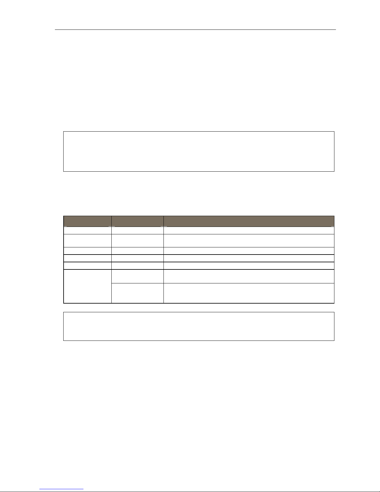
During programming, the first line of the display will show the current item being programmed, an d the se co nd
line will be the entry line. You can enter val ues as directed by the combination of the voice prompts and display .
To enter multiple values, such as a list of extension numbers, separat e each value by # (to exit the list, enter # #).
To... Press ... What this does
Enter # Confirms new or existing entry and advances to next programming step.
Back up (i.e.,
reverse direction)
Delete HOLD Deletes data or recording.
Exit [Hang up] Exits programming mode and removes extension from DND.
Help HELP Provides more detailed instructions during programming.
Select/scroll
(left-side scroll key)
(right-side scroll key)
Backs up to previous prompt without changing its value.
• During entry of a value, backs up.
• If a list is present (“>” is displayed), scrolls to left.
• Selects from options presented.
• If a list is present (“>” is displayed), scrolls to right.
• Inserts a space during entry of a name.
Notes: Either < or > in the display indicates that additional choices or values are available by pressing a
corresponding scroll key (or ).
Only one person at a time can be performing Installer or Administrator programming.
B.1
Page 6

ESI-50L Programming Manual System programming: An introducti on
Entering alphanumeric characters
You ent er names for ext en sio ns, dep ar tm ent s, br an c h IDs, CO lin es, an d guest mai lb ox es by pr es sing the
dial pad ke y that cor respon ds to th e ch ara ct er t o be ent er e d. The ke y’s possi bl e ent r ie s wil l chang e ea ch ti me
the key is pressed, and the display will show this. When the desired character appears on the display, press # to
confirm; the cursor will move to the next character position. You may move the cursor left (to correct an entry) by
pressing the left scroll key (
Key Options Key Options
0 0, - (hyphen), _ (underline) 7 P, R, S, 7
1 Q, Z, 1, “_” (space) 8 T, U, V, 8
2 A, B, C, 2 9 W, X,Y, 9
3 D, E, F, 3
4 G, H, I, 4 (right scroll key) Adds a space
5 J, K, L, 5 # [Enter]
6 M, N, O, 6 # # Ends the name
) or move right (to add a space) by pr essing t he right scroll key ().
(left scroll key) Backs up and erases
Example: To enter a B, press 2 twice (the possible options to scroll through are A, B, C and 2). When B is displayed,
press # to confi rm ; the cursor wil l move to th e ne xt cha racter to be ente red . To comp le te the name , pre ss # #.
Selectable numbering plan
The ESI-5 0L’ s selecta ble num b er in g pla n off ers t hre e pr e conf i gured thre e-digit pla ns. Wh en an ext e nsi o n rang e
is selected, department numbers and g uest mail box num bers are also changed. However, regardle ss of whi ch
extension range is selected, feature key codes, and CO line group access numbers will stay the same. The dial
plan range is s elected through Installer programming.
Note: The ESI Presence Management RFID Reader1 uses one digital extension, regardless of dial plan..
Extension num beri ng
Port card
1 (main board) 100 through 107 108 and 109
2 110 through 117 118 and 119
3 120 through 127 128 and 129
4 130 through 137 138 and 139
Digital stations Analog stations
Numbering plan selections
Selection 100 (default) Selection 200 Selection 300
From To Used for From To Used for From To Used for
100 139 Extensions 200 239 Extensions 300 339 Extensions
280 289 Departments 380 389 Departments 470 479 Departments
300 489 Guest/info mboxes 100 199 Guest/info mboxes 100 289 Guest/info mboxes
400 489 Guest/info mboxes
Extensions
Common to all ESI-50L numbering plan selections
From To Used for From To Used for
0 — Operator 71 76 CO line grps.
490 499 Q & A mailboxes 8 — CO line grp.
500 — Broadcast mailbox 9 — CO line grp./ARS
1
For more information, see the ESI Presence Management Installation Manual (ESI # 0450-0792).
B.2
501 516 Group mboxes
533 542 Cascade notif. mboxes # — Paging
600 699 System speed -dial
— Call pickup
Page 7

ESI-50L Programming Manual System programming: An introducti on
System programming overview
1 Syst em parame te rs
13 Administrator password
14 System clock
141 Set time /date
142 Automatic time setting
143 Clock adjustment
16 System feature parameters
162 Connect tone
163 Station feature set activation
17 System speed-dial
3 Extension pro gram m in g
32 Extension feature authorization
37 RFID programming
371 Access schedules
372 RFID tag programming
373 View RFID tag numbers
374 ESI Presence Management parameters
375 ESI Presence Management Reader parameters
30 Station move
1
5 Voice mail programming
53 Guest/info mailboxes
54 Group mailboxes
55 Message notification options
551 Station delivery options
552 Delivery/paging parameters
56 Cascade n o tification mailboxes
57 Q & A mailboxes
6 Recording
61 Record system prompts
62 Record directory names
63 MOH programming
631 MOH source
632 Record MOH
633 MOH volume
7 Reports
72 ESI Presence Management access door report
74 Voice mail statistics report
75 System speed-dial list
Entering programming mode
You may program from any 24-Key or 48- Key Di gital Feature Phone2 in the system:
1. Press PROGRAM
2. Press HOLD. The “enter password” prompt will play.
3. Enter the Administrator password (default is 4 5 6).
wait two seconds. You are now in programming mode. The extension will be automatically placed in
DND, and its di spl a y will show:
3
at any digital station. The normal station programming menu prompts will begin to play.
4
Then, to conf ir m t he pas swor d, ei th er pr es s # or
ADMINISTRATOR
CMD:
4. The system will play the system pro gramming menu. Fol low it to program as you wish.
5. When finished, hang up.
Warning: Always FINISH programming in ANY function BEF ORE exiting programming mode (as needed,
Note: The system will automatically exit programming mode after 10 minutes of inactivity.
Example: If your Administrator password is 864, enter programming mode by pressing PROGRAM HOLD 8 6 4 #. (To
1
Shown in the same order as it appears in the programming menu on an ESI desktop Feature Phone.
2
Although a 12-Key Feature Phone allows you to enter Installer and Admini strator prog rammi ng, we don’t recom mend tha t you use a 12-Key
Feature Phone for programming because of its one-line display and small number of programmable feature keys.
3
Or, if using the 24-Key Feature Phone, press PROG/HELP.
4
If you prefer to enter Administrator programming mode, use the Administrator password, instead (the default is 4 5 6).
press # to accept current entries for function parameters you’re not changing).
exit programming mode, hang up.)
B.3
Page 8

ESI-50L Programming Manual System programming: An introducti on
Remote setting of day, night, holiday and auto modes
Normally, the system’s day/night mode operation will be manually controlled at an ESI Feature Phone and/or set
to follow the day/nig ht mode tables (programmed by the Installer) automatically. In addition, the Admini strator
can rem otely change th e mode an d/or re- recor d the holiday gr eeting t o handle unexpected closings such as for
inclem ent weat h er.
Remotely loggi ng into the system with either the Inst aller password or the Adm inistrator pas sword lets the caller
do the following for branch IDs 1–8:
• Re-record the greetings (day, night, day2 and night2).
• Re-recor d the hol i d ay gre e ting.
• Change the mode to day/night/holiday/day2/night2 (or auto).
1. At the main greeting, enter
2. You’ll hear prompt s that will allow you to c hange the answer mode (day, night, day2, night2, holiday or
auto) and/or to re-record the holiday greeting and the main greeting (ID 1). Follow the prompts to perform the
desired operation.
4 5 6 # — or the new p assw ord — to enter rem ote programming mode.
Note: To access these options for branch IDs 1–8, you must call in on the phone number of the tenant that
3. Exit by pres sin g and hanging up.
uses those branches.
Prompts for re m ote setti ngs: an outline
1 Set answer mode
1 Day mode
2 Night m ode
3 Holiday mode
4 Use day/night table*
5 Day2 mode
6 Night 2 mode
2 Record holiday main greeting
3 Record daytime main greeting
4 Record nighttime main greeting
5 Record day2 main greeting
6 Record night2 main greeting
Note: If the system is answered live and call is then routed to a mailbox, the Administrator can press 8 to return
* This is used if the Installer has programmed an automatic calendar.
B.4
to the main greeting and then follow the steps for making remote settings.
Page 9

ESI-50L Programming Manual Function 2: CO lines
Function 1: System parameters
Function 13: Administrator password
This function will display the existing password and prompt for entry of a new password. The password can be
2–8 digits long, followed by #. Only those funct ions listed in this Administrator’s Manual can be
program me d via t he Admi ni str at or pas sw ord. The default Administrator password is 4 5 6.
Note: Be sure to write down the new password and store it in a safe place.
Accessing user station programming
Should a user f orget hi s password or if an employee leaves the organization, this feature allows the
Administrator to ent er a user's station programming and oper ate within it as if he were the user. From the
user’s station, enter the Administrator password when the system prompts for the user password.
Example: From station 105, entering 7 8 9 # or 4 5 6 # instead of the user password (1 0 5 #) will enter the station’s
user programming. (Default passwords shown for this example).
Function 14: System clock
Function 141: Set time/date
1. Enter a new t ime in a twelve-hour format.
Example: Enter 1 2 3 3 for 12:33, or 3 1 5 for 3:15 (note that you need no leading zero for the time).
2. Select AM or PM by pressing a scroll key (either or ).
3. Enter a new date in an eight-digit format, including leading zeroes.
Example: Enter 0 7 0 4 2 0 0 8 for July 4, 2008 (note that lea din g zeroe s are required here, unlike in Step 1).
4. Press # to finish the entry.
Note: A built-in battery maintains the correct time and date, even in the event of a power loss.
(Continued)
C.1
Page 10

ESI-50L Programming Manual Function 2: CO lines
Function 142: A utoma tic time setting
1: Synchronize w ith CID
This function, when enabled, synchronizes the real-time clock with Caller ID (CID) messaging: call
processing compares t he time of a CID message to t he sy stem real-time clock and, if the difference is
more than two minutes, resets t he real-time clock to match the time (hours and minutes) of the CID
message. The system will analyze each such message (or — if it receives more than four calls with CID
information w ithin a one-mi nute period — as is needed) . Select ENABLE or DISABLE by pressing a scroll
key (either
Default: Enabled.
2: Adjust for Daylight Saving Time
This function, when enabled, causes the real -time clock to adjust itself automatically for Daylight Saving
Time (DST). Select AUTO or DISABLE for DST by pressing a scroll key (eit her
DISABLE is best for thos e areas t hat don’t observe DST.
Default: Disabled.
or ). Choosing ENABLE will allow the CID data to update the time and date.
or ). Choosing
Note: If this function is enabled and it causes an automatic time change, the system won’t update the real-
time clock from Caller ID messages (Function 1421, above) for 25 hours before and 25 hours after
the time change is due to be effective (i.e., 2:00 AM Sunday).
Function 143: Clock adjustm ent
This function lets the Instal ler or Administrator have the system automatically compensate for a clock that’s
runnin g to o fast or to o slow. The clock adjust m ent spe ed s up or slows do wn t he cl oc k ov er a 30 - d ay per i od b y
the amo unt selected. If the s ystem clock is running slow, select a positive value. If the clock is running fast,
select a negative value.
Range: - 2 t o +5.5 minutes. Default: 0.
Example: If the clock is running two minutes fast over a month, select -2 (minus two minutes)..
C.2
Page 11

ESI-50L Programming Manual Function 2: CO lines
Function 16: System feature parameters
Function 162: Connect tone
This sets w het h er t he s ystem pl ay s a sy st em co nn ect t on e (t wo s hor t beeps a u ser h ears w he n a st ati o n answ er s) .
Default: Enabled ( the beep plays).
Function 163: Station featur e set activation
Field 1: Group lis t e n
With this feature disabled: if a st ation user pre s se s SPEAKER while on a call, the Feature Phone
immedi at el y tur ns off the handset a nd switches to ha nds - f r ee mod e.
If enabled, the group l isten feature is avail able system-wide. If disabled, it is no longer available.
Default: Disabled.
Field 2: Privacy release
With this feature enabled: if a station user presses a CO line key that is in use (lit red), the user will be
immediately conferenced with t he call in progress on that line. With this feature disabled, pressing an i n- us e
CO lin e key has no effect.
Default: Disabled.
Warning: Adjusting this parameter while calls are in progress may result in temporary loss of audio.
Field 4: VIP text-messaging enable/disable
With this feature enabled, VIP Professional an d VIP PC Attendant Co nsole user s ca n use VIP
to text-message.
Default: Enabled.
Function 17: System speed-dial
Up to 100 syst em sp ee d- di al nam es and a ss oci ated number s c an be stored, in lo cation nu mb ers
600–69 9, f or acc e ss by a ny station. A user ca n init i at e a system speed-di al b y di ali ng t he sp e ed- di al l o cation
number or by accessing the name through t he Esi-Dex feature. In Function 32, access to system speed-dial c an
be denied to in dividual stations (see page D. 3).
Note: System speed-dialing overrides toll restrictions (Function 32, page D.3).
1. Enter the three-digit location number to program,
2. Enter a ten-character name (see “Ent ering alphanumeric characters, ” page B.2).
Note: You must enter a name to continue.
3. Enter the number t o be dial ed (including th e line gr oup 9, 8, or 71–76). Press the left scroll ke y () to
delete any character or digit entered in error. Here’s an example:
1.
Speed-dial #
601 AUTO RENTL 915552221212
The number dialed in Step 3 can be up to 30 digits long including special characters:
Code What it produces
# # DTMF tone
2.
Name
3.
Number
C.3
Page 12

ESI-50L Programming Manual Function 2: CO lines
F Flash hook
P 2-second pause
DTMF tone
Use the scroll key to enter special characters; use the scroll key to backspace. Pr ess # to confirm the
inserted character and continue. Press # # to complete the entry.
Once t he number is saved you can use the scroll keys to move back and fort h to view the numb er. T o edit the
number, you mu st delet e it and e n ter the correct number.
Example: To create a System Speed-dial number that dials 9, then 972-555-5644, then pauses for four seconds and
9 9 7 2 5 5 5 5 6 4 4 (then scroll to) P # (then scroll to) P # (then scroll to) # # 1 0 4 #
finally dials #104, enter:
Deleting a speed -dial number
T o delete an enti r e spe ed - di al n umb er and n ame, de lete the locati on n umb er (6 X X) by pr e s sin g HOLD or
the left scroll key (
) duri ng Step 1 in the speed-dialing procedure descr ibed above.
C.4
Page 13

ESI-50L Programming Manual Function 4: Auto attendant programming
Function 3: Extension programming
This section provide s programming for extensi ons and department groups.
Important: Where any gray shading (■) appears in an example, it represents values either unavailable to the function
or unused in the particular example.
Function 30: Station move
This feature allows t he Installer or Administrator to exch ange the extension numbers of two extensions. It is used
only for excha nging extensions — not guest mailboxes or departments.
Important: Before you use this function on two extensions, make sure they’re both idle at the time.
Along with the extension numbers, this function also will exchange the following parameters (depending on
station type):
• Extension name and other assignments (including of the Operator to extensi on 0 from Functions 31 and 32).
• Mailbox information (personal greeting, notification, schedule s).
• Programmable feature keys.
• Personal Dex.
Function 30 has the following limitations:
• Mailboxes cannot be exchanged. Instead, your Installer must perform flexible number assignment .
• Both extensions must be of the same “type” — i.e.., a nalog to analog, digital to digital — as shown in the
following table:
From . . . To . . . Functi on 30 all o wed?
Digital phone Digital phone Yes
Analog extension Analog extension Yes
Digital phone Analog extension No1
Fax, mo dem, door, ringer, server,
RFID Reader
Any type of ph on e No
T o use this feature:
1. Enter Installer programming through a Digital or IP Featur e Phone and go to Function 30.
2. Enter the first exte nsion and press #.
STATION MOVE
1ST EXT: 104
3. Enter the second extension and then pres s #.
X1044 J SMITH
2ND EXT: 105
(Continued)
1
Your ESI Reseller must use an Installer function to change the numbers of these types of extensions.
D.1
Page 14

ESI-50L Programming Manual Function 4: Auto attendant programming
4. Both extensions will now appear in the display. Confirm the exchange by pressing #.
X104 J SMITH
X105 S BROWN
5. If one of the phones is in use, the display will show that extension:
STATION MOVE
EXT 104 BUSY
(If both are in use, the display will show only the first extension.)
T o back up to the previo us step, press
and then re-try the extension exch ange by pressing # again.
Function 32: Extension feature authorization
Function 321: Standard feature aut hor izatio n
The Insta ll er or Admi nist r at or ca n al lo w or de ny ma n y ext e nsi o n feat ur es o n an ext en si on - b y- extensi on basis.
A User, however, can only program and use allowed features (by using a combinatio n of voice and display
prompts) fr om hi s/ h er phone. Bel ow i s an exam pl e of a completed Fu nct i on 321 pr o gra mmi n g wor ks heet.
1.
Ext.
XXX Default Y Y N Y N Y Y Y Y N Y
100 Jane Y Y N Y N Y Y Y N N N
101 Roger Y Y N Y N Y Y N N N N X137†
102 Sally Y Y N N N Y Y Y N N N
109* Bill Y Y Y N N N N
Here are the pr ogramming steps.
1. Extension number — Enter the extension numb er to program.
2. Extension name — Name the extension (if not pr e vi ou sl y nam ed by y our I nst al l er) .
For each of the followi ng feat ures, pr ess a scroll key (
3. Call waiting — Allows the user to turn call waitin g on or off for his station.
4. Do not disturb — Allows the us er to acti vate DND from his station.
5. Auto attendant block — Blocks calls from bei ng transferred t o the stat ion fr om the auto attendant;
6. Live recording feature — If enabled, will allow the user to record conversations.
7. Service observing — Allows the us er to monitor the conver sations of t hose stations listed in the
2.
Name
3.
Call
wait
4.
DND
5.
AA
block
6.
Rec.
7.
Svc.
obs.
8.
Toll
allow
or ) to select YES or NO.
9.
Sys.
spd. dial
10.
Auto-
Page
11.
Ext.
fwdg.
1
12.
Fwdg. to
toll nos.
13.
Trk-to-
trk xfer
14.
Assoc.
ext.
follows the e xtensio n’s call forward day/night as progr am med by y our Installer.
service observing list for hi s/her station. If this is enabled, you must enter a list of allowed extensions.
Note: A Department number can be entered as an extension in the Service Observing list and will then
automatically include all members of the Department even if the members of the Department are
later changed.
8. Toll restriction — “YES” allow s the user to place toll calls. If you sel ect “NO,” the user can make only
either non-toll calls
(Continued)
†
An example of a digital Cordless Handset.
* An example of an analog phone.
1
Analog stations programmed as FAX or MODEM can’t have call waiting.
2
As determined by an Installer setting. For more information, consult your ESI Reseller.
D.2
2
or calls to num bers li sted in the allow exception table.
Page 15

ESI-50L Programming Manual Function 4: Auto attendant programming
9. System speed-dial — “YES” allows the user to access and pl ace system speed -dial calls.
10. AutoPage — Lets the user tur n Aut oPag e (d ef in ed b elo w) on or off at his/ her station.
Note: This feature is used in conjunction with the directory names recorded in Function 62. If a name
isn’t recorded in Function 62, the station default name (“Extension [xxx]”) is paged.
If the station user ha s his/ h er mail b ox set to an sw er wit h personal greet in g 3 and a caller pre sses 3 to
page that user, this feature automatically pages the station user in the page zones entered in Function 31.
If no page zone is entered, all ESI Digit al Feat ure Phones on the system are paged.
1
Default: Enabled.
Note: When AutoPage is enabled, the system will use the last installed idle digital port to perform
the page. Therefore, if a phone is on the last installed port (e.g., X107 on a system with only one
port card on the main board), the phone’s user may experience a brief delay in telephone
operation if he/she picks up the handset (or presses SPEAKER) during the AutoPage.
11. External forwarding — Allows the station user to use the call forwarding/off-premi ses and off-
premises “reach-me” features. See t he User’s Guide for m ore informatio n about these fe atures.
Default: Enabled.
Note: After the system dials the external forwarding number, it will play a prompt saying, “You are
receiving a forwarded call. Press any key to accept.” This prompt will play continuously for
30 seconds. If the forwarded call is answered and the called person dials a digit, the forwarded
call will be connected to that person. If no digit is dialed, the caller is automatically forwarded to
voice mail. While the two lines (trunks) are connected, the system constantly monitors the line for
open loop conditions (hang-up). If an open loop is detected on either line, the call is disconnected.
The system also monitors for voice activity on the connected lines; if voice is no longer detected,
the call is disconnected. Finally, if both lines are connected for more than 60 minutes,2 the call will
be disconnected.
12. Forwarding to toll numbers — This feature is used in conjunction with external forwarding (see previous
item). When enabled, this feature lets the user program a long-distance number for external forw arding.
Default: Disabled.
(Continued)
1
ESI Cordless Handsets don’t receive pages.
2
Default timer setting. To adjust this, contact ESI Technical Support.
D.3
Page 16

ESI-50L Programming Manual Function 4: Auto attendant programming
13. Trunk-to-trunk transfer — When enabled, this lets the station user initiate a trunk-to-trunk transfer.
The user, while conne cted to a CO line, can pr ess TRANSFER, dial an off - sit e nu mb er and t he n
compl ete the trunk-to-tru nk transfer by simply ha n ging up. Both outside parties are then connected.
A station user also can set up a conference call and then drop out of the c onference, leaving th e other
members conferenced. This feature MUST be enabled in order for external call forw arding and/or
off-premises “reach-me” to succeed.
Default: Enabled.
Important: USE OF FEATURES, SUCH AS TRUNK-TO-TRUNK TRANSFER, THAT REQUIRE TRUNK-TO-TRUNK
CONNECTIONS WILL INCREASE THE RISK OF TOLL FRAUD. IN NO EVENT SHALL ESI (ESTECH
SYSTEMS, INC.) BE LIABLE FOR ANY DIRECT, INDIRECT, INCIDENTAL OR CONSEQUENTIAL DAMAGES
WHATSOEVER INCLUDING, BUT NOT LIMITED TO, FRAUDULENT TOLL CHARGE S, LO SS OF BUSINESS
PROFITS, BUSINESS INTERRUPTIONS OR ANY OTHER COSTS OR DAMAGES RELATED THERETO
ARISING FROM THE USE OF THESE FEATURES.
14. Associated ext en sio n — Enter the desired ESI Cordless Handset extension. This cr eates a
relationship that allows use of the Qui ck Swit c h key . For informatio n about t he Quick Switch key,
consult the User’s Guide (ESI # 0450-1135). This field is not avai la bl e for an ext en si on u sin g a 12 - Ke y
Feature Phone or ESI Cordless Handset.
Example: Here is a portion of a completed programming worksheet for extension feature authorization. Note that:
• Extension 100 cannot record calls but can make toll calls (except those listed in the deny table) and
can access the system speed-dial numbers.
• By comparison, extension 102 cannot make general toll calls but also can call any system speed-dial
number, even if it’s a toll call, even those listed in the allow table.
• Extension 102 is associated with an ESI Digital Cordless Handset at extension 113.
• (Extension 108 doesn’t have DND, AA block, recording, or service observing capability because it’s
an analog port.)
1.
2.
Ext.
Name
100 Jane Y Y N N N Y Y N N N N
102 Sally Y Y N Y N N Y Y N N N X113
Bill Y Y Y N N N N
108*
(Sally’s
113
Cordless)
3.
4.
5.
6.
7.
8.
9.
10.
11.
Call
wait
AA
Svc.
Toll
Sys.
Auto-
DND
blk.
Rec.
obsv.
allow
spd. dial
Y Y N Y N N Y Y N N N X102
Page
Ext.
fwdg.
12.
Fwdg. to
toll nos.
13.
Trk.-to-
trk. xfer
14.
Assoc.
ext.
* An example of an analog phone.
D.4
Page 17

ESI-50L Programming Manual Function 4: Auto attendant programming
Pair ed ES I Fe a t ure Phone/ ana log phone oper a t ion
For some one wi shi n g to ha ve a n ESI Feature Phon e in hi s off ic e and an e xist i n g anal og c ordl e ss ph on e
for roami n g the bui l di ng, pr ogr am a s foll ow s:
1. Create a call-forward key on the ESI Feature Phone to forward to the analog c ordless phone.
2. Assign the analog cordless phone’s call forward busy/no answer to the ESI Feature Phone’s mailbox.
The user will then have all of his messages in one location (but can retrieve them from either phone).
Function 322: A dvanced extension feature authorization
This function allows authorizatio n of some other ESI featur es, particularly tho se invol ving licensing.
Below is an example of a completed Function 322 programming work sheet.
1.
2.
Ext.
Name
XXX Default N
100 Jane Y Attendant
101 Roger Y Pro Y 30
102 Sally Y VIP
109* Bill N
1. Ext. — Enter the extension number to program.
2. Name — Enter the name of the extensio n.
3.
VIP
4.
Type
5.
Auto-record
N
6.
Record threshold
Note: For more information on the VIP, VIP Professional, and VIP PC Attendant Console products and
features mentioned in steps 3–6, refer to the VIP Setup and User’s Guide (ESI # 0450-0513).
3. VIP — Scroll to enable (YES) or di sable (NO) the ext ension to use VIP, VIP Profession al, or VIP PC
Attend ant Co ns ol e.
4. Type — Scroll to select which type of VIP ap plication the extension can use.
Choices: VIP (regular VIP), PRO (VIP Professi onal), an d ATTEND (VIP PC Attendant Console).
5. Auto-record — Scroll to enable (YES) or disable (NO) the extension for auto-record. This feature requires
appropriate licensi ng
1
and is available only for users of VIP Professional and VIP PC Attendant Console.
6. Record threshold — Enter the num ber of aut o-rec ordings that an authorized extension can make
before all recording functi onality is disa bled. For infor m ation on auto- recording, consult the VIP Setup
and User’s Guide (ESI # 0450-0513).
Range: 5–15. Default: 10.
* An example of an analog phone.
1
The system supports up to two auto-record licenses.
D.5
Page 18

ESI-50L Programming Manual Function 4: Auto attendant programming
Function 37: RFID programming
This function relates to ESI Presence Management onl y, and covers several steps needed t o:
• Program RFID tags.
• Access scheduling.
• View tag numbers.
• Set ESI Presence Management par am eters.
Note: For more information about ESI Presence Management, consult its Installation Manual (ESI # 0450-0792).
Function 371: A ccess schedule pr ogr amm ing
Access sc hedules are used to allow or deny door access with electronic keys (“RFID tag s” on the system
display) at ce rtain times of the day. Up to seven access schedules can be programmed. Each schedule has
an allow ac ce s s time a nd a deny ac ce s s tim e for ea ch d ay of t he we ek. By default, all a cc ess s ch ed ule s al lo w
acces s 24 hours a day, seven days a week.
Note: Access schedules don’t take effect until the current time has passed the next schedule time.
1. Using the s cr oll key s, sel ect th e ac cess s ch ed ul e to b e pr ogr a mmed. Pre s s # to confirm.
Range: 1–7.
For example: if you program a schedule time to deny access Wednesdays at 5:30 PM but it’s
already 5:45 PM on Wednesday when this programming occurs, the change won’t take effect until
the following Wednesday.
Note: Schedule 0 (default of full-time access) isn’t selectable.
ACCESS SCHEDULES
1-ACC SCHED1 >
2. Enter the n am e of the schedule (up to 10 chara cters in length) .
Press # to confirm.
Default: ACC SCHED[x], where [x] represents the access schedule select ed in st ep 1.
ACC SCHED1
NAME:
3. Use the scr oll keys to select the d ay of the week to program for the selected access schedul e.
Press # to confirm.
ACC SCHED1
DAY: MONDAY >
If you haven’t yet assigned an allow time (see next step) for this schedule, the display will show
something like:
ACC SCHED1 MON
NO ALLOW TIME
(Continued)
D.6
Page 19

ESI-50L Programming Manual Function 4: Auto attendant programming
4. En ter t he allow tim e — t he ti me wh en an el ectronic ke y user c an begi n c ontrolli ng do or lo cks — i n
12-hour format. (To delete an ent ry, press HOLD.)
Press # to confirm when done.
ACC SCHED1 MON
ALLOW: 900
5. Select AM or PM by pre ssi ng a scroll key. Press # to confirm.
ACC SCHED1 MON
ALLOW: 900 AM
If you haven’t yet assigned a deny time (next step) for this schedule, the display will show something like:
ACC SCHED1 MON
NO DENY TIME
6. Now, enter t he deny t ime — th e time when an ele ctronic key user begins to be denied door lock
control — in 12-hour format. (T o delete an entry , press HOLD.)
Press # to confirm when done.
ACC SCHED1 MON
DENY: 700 >
7. Select AM or PM by pre ssi ng a scroll key. Press # to confirm.
ACC SCHED1 MON
DENY: 700 PM
8. Press # again to exit the function, or select an other day of the week by using the scroll keys and then
go back to ste p 4.
D.7
Page 20

ESI-50L Programming Manual Function 4: Auto attendant programming
Function 372: RFID tag num ber pr ogr amm i ng
As descri b ed earl i er in thi s do cum e nt, eac h ele ctr o ni c ke y has an emb ed ded unique RFID tag number. This
functi on is used to associate each RFID tag number to an extension or mailb ox for Personal Call Routing and
presence indi cation (except mailb oxes). If Personal Call Routin g or prese nce indi cation is not desired but
access control is required, enter 0 instead of an extension or mailbox number.
1. Enter an RFID tag number, or use the scroll k eys to select from the list of t ag numbers.
Note: If using any RFID features — i.e., if using ESI Presence Management for anything more than its
doorphone capabilities — you should save time by first scanning the electronic keys at any ESI
Presence Management RFID Reader connected to the system. The system will store the
electronic keys’ tag numbers automatically, and you can use the scroll keys to select the tag
numbers to be assigned.
To delete a tag number, press HOLD.) Pre ss # to confirm.
TAG ID: 2
9012345678 >
The tag ID is the list index of the RFID tag number.
Note: If a tag number is entered manually but the 500-tag limit has been exceeded, “LICENSE
EXCEEDED” will appear on the display. Therefore, you must either delete one or more
unassigned tag numbers or purchase additional licenses to add new tag numbers. For the
system’ s total numb er of RFI D licen se s, con sult your ESI Resell er.
2. Enter the extensio n or mail box number to which you wish to assign the tag number. If no extension or
mailbox is to be assigned this tag number, press 0. (To delete an entry, press HOLD.)
Press # to confirm.
RFID TAG PROG
EXT OR MB:
3. Enter the extension numbers of up to 10 ESI Pr esence Management RFID Readers for which this tag is
allowed to control door access. To give the tag access to all do or s, pr e ss FLASH. (To delete an entry,
press HOLD.) Press # after each entry and then pres s # again to confirm (in other words: after th e last
entry, you’ll press # twice).
Note: If all ESI Presence Management RFID Readers are allowed, “ALL” will appear on the second line.
DOOR ACCESS:
123 124 138 >
4. Use the scroll keys to select an access schedule. Access s ch ed ule s ar e used t o all o w or deny d oor
acces s with an e lectronic ke y at certain time s of the day. Each day of the week c an have a start time
to allow acc es s an d a stop time to deny access. To allow constant (“full”) door access, select 0 -
FULL. Otherwise, select a schedule to restrict access. The schedule name will appear .
Range: 1–7. Default: 0 (full)
Note: You assign access schedules in Function 371 (see page D.6). If not using access schedules,
select 0 – FULL.
ACCESS SCHEDULE:
0 - FULL >
D.8
Page 21

ESI-50L Programming Manual Function 4: Auto attendant programming
Function 373: View R FID tag num ber
This is used t o displa y tag numbers that are associate d to exte nsions or mailbo xes. You can only view tag
number s with t his function. You cannot change any tag numbers or assi gnments.
Enter the station or mai lbox number to display, and then pr ess #. If there’s an RFID tag number assigned to
that extension or mailbox, it will appear.
RFID TAG DISPLAY
EXT:
Tip: You can use ESI System Programmer or ESI System Admini strato r to print out a list of assigned
tag numbers.
Function 374: ESI P r esence Managem ent par am eters
Playi ng prompts
This determines whether the system pla ys a prompt — and, if so, which one — when the ESI Presence
Managem ent RFID Re a der rea ds an electronic key . Select YES to enable playi ng of the prompt or NO to
disabl e pla yi ng of the pr om pt.
Default: YES (a prompt will play).
EPM RFID READER
PROMPTS: YES >
When this functi on is set to NO, no prompts will play through the ESI Presence Management RFID Reader.
When “EPM RFID Reader prompts” is set to YES, prompts will play as shown below. (These prompts can’t
be customized.)
When the RFID Reader displays: It plays this prompt:
WELCOME “Welcome”
GOODBYE “Goodbye”
ACCESS DENIED “Invalid Entry”
LICENSE EXCEEDED “Error”
ERROR
READER FULL
“Error”
Enable/disable sending time and attendance records
Notes: The NSP must be programmed and connected to a local area network for time and attendance
record collection .
Only ESI Presence Management RFID Readers programmed as type ENTRANCE/EXIT (Function 31 )
generate time and attendance records.
This parameter is used when the optional ESI TimeLine time and attendance management software
appli cation is used in co nj un cti o n wit h the ESI Pre se nce M ana gem ent RFI D Rea der.
Use the scroll keys to enable or disable time and attendance r ecords, and pre ss # to confirm.
Default: Disabled.
D.9
Page 22

ESI-50L Programming Manual Function 4: Auto attendant programming
Function 375: RFID Reader par ameter s
This function is used to adjust the doorphone speaker volume of each RFID Reader.
1. Enter the extension number of the RFID Reader.
EPM READER SET
EXT:
2. Select the volume level by using t he scroll keys.
X211 FRONT DOOR
VOLUME: 6 >
Range: 1–8, with 8 as the highest. Default: 4.
D.10
Page 23

ESI-50L Programming Manual Function 5: Voice mail progr amming
Function 5: V oice mail programming
T o simplify initial installation, all programmed extensions will automatically have t he generic personal greeting,
“You h ave reached the mai lbox f or extension [xxx].” The mail box us er sh oul d replace this wi th a personali z ed
greeting. Each mailbox must have a greeting recorded for the ESI system to consider the mailbox active.
Function 53: Guest/info mailboxes
Any gue st mailb ox can be programmed as either a guest or info mailbox.1 Enter the mailbox number and select
Guest or Info by pressin g a scroll (
Guest mailboxes
Guest mailboxes are designed to be used by personnel, such as in outside sales or manufacturing, who
don’t ha ve an ext e nsi on a ssi g ne d to the m.
or ) key.
Notes: A guest mailbox can be handled like a regular extension (i.e., listed in the directory, assigned a station key,
etc.), and is password-protected by default.
Guest mailboxes do not support AutoPage (but do support off-premises “reach-me”).
Info mailboxes
Info mailboxes can be used to give call ers inform at io n on a va r iet y of dif f er ent su bj ect s by “ publishing” t hes e
mailbox numbers. Info mailboxes are identical to guest mailboxes except that the caller will not be given a
record tone after the personal greeting (the information to be played). Instead, the caller will be forwarded as
programmed in this function (default is the caller will be disconnected af ter the information is played).
Guest/info mailboxes are created or deleted here, but are turned “on” only when a personal greeting (the
information to be played) has been recorded. Deleting the personal greetings will turn “off” the mailbox.
T o record a greeting, press PROGRAM
prompts. The default password is the mailbox number. The maximum length of the recording time is 14 minutes.
Below is an example of a complet ed Program ming W orksheet, showing t he sequence of programming:
1.
2.
MB
Name
400 Dana Guest Y 9
402 Literature Info MB 501 MB 501
3.
Type
Each programming step is defined as follows:
1. Mailbox number — Enter a guest mailbox number.
2. Name — The mailbox name is used for the display, reports, and as a programming aid. The name
length c an be no lo ng er th an 1 0 char act ers (see “Ent er in g al ph an umer i c ch aracters,” pa ge B.2) .
Default: The Mailbox num b er .
3. Type — Select a mailbox type: Guest or Info.
Default: Guest.
4. External forward (guest mailbox onl y) — A guest m ail box can be set to al low off - pr emises “r each- me. ”
Default: No.
5. Line group — Use d for off-premises “reac h- m e.”
Default: 9.
6. and 7. Cal l forwar d (info mailbox only) — An info mailbox can be set to call forward after the personal
greeting has played to an extension, department, a mailbox or a bran ch ID for day mode and dif fer ently
for night mode.
Default: ID9999 ( automatic disconnect) .
and the mailbox number; then press # to confi rm, and follow t he
4.
Ext. fwd.
5.
Line grp.
6.
CF day
7.
CF night
1
Guest and info mailboxes’ range depends on dial plan selec ted (see “Numb erin g plan sele ctio ns,” page B.2).
E.1
Page 24

ESI-50L Programming Manual Function 5: Voice mail progr amming
Function 54: Group mailboxes and the broadcast mailbox
Broadcast mailbox
The broadcast mailbox1 is a special gr o up mai l bo x which can be used to l ea ve me s sa ge s for all of the
system’s station users who have recorded a personal greeting. The broadcast mailbox’s user list cannot be
edited. Guest mailboxes are not included in the broadcast group.
Group mai lboxe s
Group mailboxes can be used for q u ickly leaving the same message simultaneously in many individual
users’ mailboxes. Anyone who knows the password can leave messages for all users listed as members of
that gro up an d who hav e re cor d ed a pers o nal gr e eting. (If no memb er has a per s on al gr eet in g re cor de d, the
group m ailbox won’t save any messages.) The In staller, Administr a tor or group mailbox “ owner(s) ” may set or
change the list of group mail box members. To recor d a greeting, press PROGRAM
number; then press # to confirm, and f ollow the prompts. The default password is the mailbox number. The
maximum recording length is controlled by Function 51; the default is 10 minutes.
and the mailbox
Important: A group mailbox is turned “on” (able to record and playback messages) only when its “owner” has
recorded a greeting for it, such as “This is the group mailbox for East Coast Regional Sales.” Similarl y,
deleting the group mailbox greeting will turn “off” the group mailbox; any outstanding messages will
remain in its members’ mailboxes until erased by each member.
Notes: Programming 0 (zero) as the password lets anyone leave group messages or program the group mailbox.
If a user saves a group message, it will be saved as a new message.
Broadcast and group mailboxes can have a maximum of 32 messages per mailbox.
When a message is deleted from the group mailbox, this deletes all copies from its member mailboxes.
Conversely, when the last user to delete his/her copy of the message does so, this deletes the message
from the group mailbox.
Here is the programming sequence:
1. Enter the group mail box number.
2. Enter group member mailboxes’ numbers —
Separate each by #; enter # # to end the list.
Range: Depe n ds on di al plan s el ected (see
“Numbering plan selections,” page B.2).
1
1.
2.
MB
Group member mailboxes’ numbers
501 102 104 106 107 122 303 314
1
Mailbox numbering depends on the selected dial plan; see page B.2.
E.2
Page 25

ESI-50L Programming Manual Function 5: Voice mail progr amming
Function 55: Message notification
On a mailbox-by-mailbox basis for user or guest mailboxes, the system can be programmed to call an off-premises
number or another extension to deliver messages or dial to an external commercial paging network to activate a
user's pager. The ESI-50L will call or page when the first new message has been left in a mailbox and will repeat
(at the interval of minutes programmed in this function) until the new message(s) have been deleted, saved or
moved. The user can program either a phone or pager numb er . The Inst al ler an d Admini strator c an set, on an
individual-stati on basis:
• The number to be called
• A delay period
• The number of attempts (maximum of 99)
• The interv al bet w een at te mpts
• A “quiet peri od " to su s pend ph on e delivery — e.g., lat e at nig ht (the quiet period is a n on-and-off t ime that
applies to all days of the week)
Note: Only pager or phone notification can be programmed, not both.
Function 551: Station delivery op tions
Programm ing of the station options, a s shown b elow, can be pe rformed by the Installer or Adm inistrator .
In additi o n, the user can ch a ng e his/her phon e number an d pa ger num ber (but n ot pho ne or pager del a y
time). The phone number’s maximum length is 24 d igits.
1.
Number
1. Phone 2145556789 30 6 60 10:30PM 7:15AM
2. Pager 2145551234 0 10 30
2.
Delay
3.
Attempts
4.
Interval
5.
Quiet on
6.
Quiet off
T o program, ent er t he stat i o n/e xt en si on num ber an d ch oose 1 for phone number or 2 for pager n umb er.
Then, ent er :
1. Phone/pag er number — The number to be dial e d (without the CO line group [9, 8, or 71–76]).
2. Delay — How many minutes the system is to wait before dialing the phone or pager num ber.
This allows the user t o pick up a message i f he is in the of fice.
Range: 0–500. Default: 0.
3. Attempts — How many times the system will call/page.
Range: 0 –99. (0 turns off delivery.) Default: 3.
4. Interval — H ow many minutes should elapse between attempts.
Range: 10–1440. Default: 30.
5. Quiet period on — When the quiet period should begin.
Default: (None.)
6. Quiet period of f — When t he qu iet period should e nd.
Default: (None.)
Notes: For the Quiet period on or Quiet period off parameters, a value in either of 0:00 is invalid and will
Code What it produces
# # DTMF tone
F Flash hook
P Two-second pause
cause notification not to work.
To insert a special code, press the right scroll key () to select the desired special code:
# , , F or P (see below). Press # to confirm the inserted character and continue.
Press # # to complete the entry. Use the down arrow key () to backspace.
Once the number is saved you can use the scroll keys to move back and forth to view the number.
To edit the number, you must delete it and enter the correct number.
DTMF tone
E.3
Page 26

ESI-50L Programming Manual Function 5: Voice mail progr amming
Function 552: Delivery/paging p ar am eter s
The sequence of programming is as follows:
1. CO line access — Enter the CO line group (9, 8, or 71–7 6) t hat is to be accessed for delivery.
Default: 9.
2. Pager diali ng pause — When paging, the system will send the mailbox number to be shown in the
pager’s display. To allow time for the paging service to answer, enter the pause, in seconds, to occur
between wh en t he s yst em di al s the pa ger nu mb er and wh en it the n di al s th e mail b ox number.
Range: 0–20. Default: 6.
Note: The message notification and delivery process uses one CO line at a time. As a result, if a system has
multiple users who have programmed delivery options, there may be a delay in notification.
Function 56: Cascade notification mailboxes
In addit ion to individual mailbox paging, ESI-50L can support up to 10 cascade notification mailboxes (533–542).
These can be assigned to anyone who requires escalating levels of notificat ion beyond the sin gle level avail able
in all user mailboxes. In thi s function, you program the notification n u mbers and number of times each is to be
notified before the n ext notification number is dialed; ad ditionally , the mailbox owner can program thes e setti ngs.
T o record a greeting, press PROGRAM
prompts. The default password is the mailbox number. The maximum recording length is controlled by Function 51;
the defaul t i s 10 mi n ute s.
Cascade mailbox options
The user can program up t o three external number s, of up t o 24 digi ts each, to be cal led or paged whenever
the mailbox takes a new or urgent message. The system will dial the first number (for the number of times
liste d), the n dial the second paging number (for the number of times li sted), and finally dial the third number,
continuing in this sequence to call all three numbers unti l the message has been ret rieve d.
1.
MB
533 2145553232 PHONE 2 2145554254 PHONE 3 2145555452 PAGER
T o program thi s, enter:
1. The mailbox number — Range: 533–542. [ Th en pre s s 1 to enter num ber pr o gr amming, and pr o ce ed
to Step 2.]
2. First number — The number to be di ale d (without the CO line group).
3. Type — PHONE or PAGER. Use scroll keys to select.
4. Attempts — How many times the system will call before adding the second number.
Range: 0–99 (0 immediately pages all numbers). Default: 1.
5. Second number — The number to be dialed (without the CO line group).
6. Type — PHONE or PAGER. Use scroll keys to select.
7. Attempts — How many times the system will call before adding the third number.
Range: 0–99. Default: 1.
8. Third number — The number to be dialed (without the CO line group).
9. Type — PHONE or PAGER. Use scroll keys to select.
2.
1st Number
3.
Type
and the mailbox nu m ber; the n press # to confirm, and follow the
4.
Attempts
5.
2nd Number
6.
Type
7.
Attempts
8.
3rd Number
9.
Type
Note: Use the scroll key to enter special characters; use the scrol l ke y to backsp ace. Pre s s # to
E.4
confirm the inserted character and continue. Press # # to complete the entry.
To change the number, delete and then re-enter it.
Page 27

ESI-50L Programming Manual Function 5: Voice mail progr amming
Cascade notification parameters
The cascade notification mailboxes will use the same CO line group and pager dialing pause as programmed
in Function 552 (see page E.4).
Notification interval
T o program the notific ation interval parameter for a cascade notification m ailbox:
1. Enter the mailbox number (5 33–542).
2. Press 2 to set parameters for the mailbox.
3. Enter the num ber of mi nutes f or the interval between attempt s.
Range: 1–1440. Default: 30.
Function 57: Q & A mailboxes
You can create questio n and answer (Q & A) mai lboxes (490–499). Each Q & A mailbox owner can record up
to 10 questions. The q uestion s are recorded in the same manner as recording us ers’ multiple personal gr eetings
(see the User’s Guide, ESI # 0450-1135). Th e indi vi d ual a ns wer segme nt s re cor de d by t he cal ler are stored as a
single message, with the answer segments separated by short beep ton es. Each answer segment' s maxim um
length will be as programmed by your Installer. Normal message handling capability — delete, save, etc. —
applies to the entir e m essage (all se gm ents).
The caller, when recording ea ch answer, can be instructed to conclude by pressing 1 or to pause for the next
questi o n (th e sy stem ad v an ces wh en it detects ei t her a 3 - se c o nd period of sile n ce or th e pre ssi ng of 1) — e.g.,
"Record your n a m e at the tone and press 1 when finished”… “Record your ad dress at the tone and press 1
when finished." If the caller fail s to respond to tw o questi ons in a row, t he system disconnects the cal l.
Important: This programming creates or deletes Q & A mailboxes, but these mailboxes are turned “on” only when the
mailbox owner has recorded questions. Similarly, deleting all questions turns “off” the mailbox.
To record quest i ons, press PROGRAM and the mailbox number; t hen press # to confirm, and follow the prompt s.
The default password is the mailbox number. The maximum recording length is controlled by Functi on 51; the
default is 10 minutes.
Here is an example of a completed programming worksheet (numbers correspond to steps on next page):
1.
2.
MB
Name
490 Employment ID 9999 ID 9999
491 Survey ID 9999 ID 9999
3.
CF day
4.
CF night
Each programming step is defined as follows:
1. Mailbox number — Ent er a Q & A m ailbox num ber.
2. Name — The mailbo x name is used for the display , reports, and as a pr ogramming aid. The name length
can be n o longer than 10 characters (see “Entering alph anumeric characters,” page B.2).
Default: The mailbox num b er .
3. & 4. Call forward — A Q & A mailbox can be set to call forward, aft er the la st question has been
answer ed, to an extensi on, department, a mailbox or a branch ID for day mode and di fferently for night
mode.
Default: ID9999 ( automatic disconnect).
Tip: If you need a Q & A mailbox with more than 10 questions, set the call-forwarding to another
Q & A mailbox.
E.5
Page 28

ESI-50L Programming Manual Function 6: Recording
Function 6: Recording
Function 61: Re-record main greeting
The mai n greeting prompts are r e-rec orded here.
Recording a pr ompt
1. Practice the prompt by recording and re-recording (start and stop by pressing 1).
2. When sati sfied with its quality, press # to confirm.
Note: Deleting a system prompt by pressing HOLD (instead of #) restores to the default recording.
System prompts
• Busy (530) — Plays to the outside caller if an extension is busy.
Default: "That extension is busy.”
• No answer (531) — Plays to th e caller if an extension does not answer.
Default: "That extension does not answer.”
• Hold (532) — Plays to the caller who makes a menu selection or enter s an extension number.
Default: "One moment, ple ase.”
• Q/Z (534) — Plays to a caller who has selected an alphabetic directory; instructs the caller to press 1 for the
letters Q or Z since these two letters do not appear o n the phone ke ypad; plays at the end of the first
directory prompt (but only if a name in the directory start s with a Q or Z).
Default: "For the letters Q or Z, use key number 1. ”
• No names matched (535) — Plays to the call er if, in a directory branch, the first letter he/s he selected has
no names associ ated with it, or if he/she has listened to all of the names play ed and has m ade no
selection. After playing th e prompt, the E SI system forwards the cal l to the extensi on, branch or mailbox as
programmed in call forward no response.
Default: "No names matched; one moment please.”
• End of message (537) — Plays after a c aller leaving a m essage presses 1 to stop recording; the prom pt
then tells the caller his/her options.
Default: “To continue this recording, press 1; to return to t he main m enu, press 8; or, if finishe d, press
and han g up.”
• Holiday main greeting (540) — Plays to callers when the system has been manually placed in holiday mode.
Default: "Thank you for calling. Our off ice is closed i n observance of t he holid ay. You may dial your party’s
extension, at any time, or please call back during regular business hours.”
Note: While in holiday mode, the system follows night mode programming for call routing.
• VIP PC Attendant Co nsol e Queue Prompts: 648, 649 — Pla ys t o callers when th ey ar e automatically or
manual ly placed in the Attendant Queue in VIP PC Att end ant Con sol e .
F.1
Default: “All atte n dant s are c ur re nt ly b usy. One moment, pl e as e. ”
Note: Deleting a system prompt by pressing HOLD (instead of #) restores to the default recording.
Page 29

ESI-50L Programming Manual Function 6: Recording
Function 62: Record directory names
This function is accessible only if a directory branch has been cr eated as part of auto att endant programming.
Enter the extension number and record the name. If this is a by-alp ha branch, the s ystem wil l automat ically set
the name ke y usi ng the n ame a ssigned in Fun ct io ns 3 1, 33, or 53; if nec es sary, enter a differe nt nam e key.
Important: Make photocopies of the blank worksheet for preparing directories and making future changes. As names
1.
Ext.
102 John Jones 5 6 4
113 Janet Smith 5 2 6
change, the Administrator can enter this function and change any field via the Administrator password.
2.
Recorded name
3.
Key
Each programming step is defined as follows:
1. Extension number — Enter t he extension number for the directory name.
2. Record name — Press 1 to begin recording and press 1 again when finished.
3. Name key — (Necessary if the directory type is alpha [consult your Installer for more information.)
Enter the numeric equivalent to the letters appearing on a phone keypad (for Q or Z, use 1). Up to three
numbers may be entered. Your ESI Reseller can give you more information about this.
A by-alpha directory branch allows the caller to be connected to a system user by selecting his/her name from a
directory . The alpha directory has two prompts: the first instructs the caller t o enter t he fir st three letters of the
individual’ s f ir st or last nam e; the second i nstr ucts t he cal ler t o press # when he/she hears the desi red indivi dual’s
name. The system then plays the matched names to the caller, in alphabetical order according to the extension
names pr ogr amm ed by y our Inst al l er.
With the name key set to three digits, when a caller selects a directory bra nch and dials only one or two digits to
select a name, the system will wait three seconds for the entry of another digit. If the system receives no other
digit within that time, the auto attendant will begin to play, in alphabetical order, the subset of directory names
bounde d by the di gi t s dia le d.
Examples: Caller dials 5 and waits three seconds. The system plays names beginning with J, K, and L.
Caller dials 3 2 and waits three seconds. The system pla ys name s beginning with DA through FC.
Caller dials 7 7 2. The system plays names beginning with PPA through SSC.
If a user dials more than three digits, the system ignor es the additional digits (except for the # key , which si gn al s
the directory to connect the caller to the extension or department associated with the di rectory entr y that’s playing).
Note: To re-record the prompt that says, “Enter the first three letters of the person’s last name,” you must enter
Function 61 and then enter the ID number of the directory branch.
F.2
Page 30

ESI-50L Programming Manual Function 6: Recording
Function 63: Message-on-hold (MOH) programming
MOH can be:
• A live feed from an external music source connected to the MOH connector located on the side of
the cabi net .
• One of three default, generic MOHs pre-recorded by the fact ory.
• A custom MOH loaded into the system by using a cassette recorder plugged into the MOH connector.
Function 631: MOH sourc e
This selects the source for the system that will be played to callers on hold.
Code Source
590 Live external source*
591 Pre-recorded music
592 Pre-recorded with “please continue to hold”
593 Pre-recorded with “dial 0 or extension from hold”
594 Customer-recorded message on hold
595 Customer-recorded message on hold
596 Customer-recorded message on hold
597 Customer-recorded message on hold
598 Customer-recorded message on hold
599 Customer-recorded message on hold
600 Customer-recorded message on hold
601 Customer-recorded message on hold
602 Customer-recorded message on hold
* Dialing off-hold doesn’ t work (can still dial off greetings and announcements).
Default: 592 (gen eric message-on-hold) .
Function 632: MOH recording
1. Connect th e messa ge/music source to the MO H port on t he side of the cabinet.
Note: The connector is monophonic-only — if you use a stereo source, you must either set it to output
mono, if possible, or use a stereo-to-mono conversion cable (or adapter).
2. Enter the prompt number to be recorded.
3. Press 1 to begin recording. To aid you in queuing, the source will be played through the
phone’s speaker.
Note: The recorded material should not have a “beginning” or “end” — so that playback can loop
continuously. The maximum record length is controlled by the amount of space available on the
Memory Module.
4. Press 1 when finished. The recording will play back so you can review it.
5. Press # to accept the recording.
Function 633: MOH volume
If a custom MOH is recorded, t he output volume can be adjusted in this f unction.
Range: 1 (faint)–12 (loudest). Default: 6.
Notes: If an external audio source such as a radio is used for MOH, adjust the volume at the source.
F.3
To turn live MOH volume completely off, turn off volume at the source.
To turn recorded MOH volume completely off, select (in Function 631) one of the prompts in the range
of 594–598, but make sure it’s blank. These prompts are blank by default; if you have recorded some
audio on all of them, just select one and record a few seconds of silence.
Page 31

ESI Communicatio ns Servers Program m ing Manual Function 7: Reports
Function 7: Reports
Important: You may wish to read “Feature description: SMDR” (beginning on page H.1) before using this function.
Report printing
The system’s built -i n r ep ort s ca n be out put to a pri nt er or a PC via the Maintenance/SMDR por t.
When printing captur ed reports from the PC to a laser pr inter, use a fi xed monoproportional fo nt (such as Andal e
Mono, C ourier N ew or Letter Gothic), 9 points or s maller.
From either th e Installer or Administrator programming menu, sele ct the desired report as shown in Functions
72, 74 and 75 (st art i ng b elow) . The reports c an be printed with either: (1) the data saved for inclusion in f uture
reports, or (2) the data and totals cleared. (You can’t clear data in either the system program report or the
system speed-dial re port.)
Reporting functions
• Function 72: ESI Presence Management access door report — Provides hist orical data on
access door entry.
• Function 74: Voice mail statistics report — Pr ovides statist ics indicating the message act ivity in each
mailbox since the dat a was last cleared.
• Functi on 75: Sy st em sp ee d- di al li st — Lists the current system speed-dial numbers. Distribute a copy to
those who are authorized to use them.
Function 72: ESI Presence Management access door report
The ESI Presence Managem ent ac cess door report is available to the Installer and System Administrator, and is
based o n histor ical data for t he desir ed access door RFID Reader.
The report contains records of extensions/m ailboxes, names, RFID tag numbers, and the date and ti m e from the
10,000 most recent records for access-only door (not entrance/exit) RFID Readers in the system. Once the l imit
of 10,000 is r eached, older records are discarded as newer records are stored. Initializing the system deletes all
stored records.
1. Enter the extension number of the desired a ccess door RFID Reader, and press #.
EPM READER
EXT: 123
2. Enter the start tim e in 12-hour, HHMM format, and press #.
ENTER START TIME
3. Use the scroll keys to select AM or PM for the start time, and press #.
ENTER AM OR PM
(Continued)
1
1
For reference, if necessary, consult the ESI Presence Management Installation Manual (ESI #0450-0792).
G.1
Page 32

ESI Communicatio ns Servers Program m ing Manual Function 7: Reports
4. The eight-digit start d ate for this repor t is co m posed of t wo digits for t he month, two digits for the day, and
four digits for the year. The start date should be t oday’s date or earlier. Enter the start date in MMDDYYYY
format, and press #.
ENTER START DATE
5. Enter the end time in 12-hour, HHMM format, and press #.
ENTER END TIME
6. Use the scroll keys to select AM or PM for the end time, an d press #.
ENTER AM OR PM
7. The eight-digit end date for this report is compos ed of two digits for the month, two digits for th e day, and
four digits for the year. The end date should be no earl ier th an the start date. Enter t he end date in
MMDDYYYY format, and pres s #.
ENTER END DATE
8. To print the report, press 1 and then #.
PRESS 1 TO PRINT
REPORT
Here’s an e xam ple of an ac ces s do or re port for an RFI D Rea der :
Notes: Extensions and mailboxes are reported as four digits each, regardless of your numbering plan selection.
Each RFID tag that hasn’t been assigned an extension or mailbox is reported as 0000.
G.2
Page 33

ESI-50L Programming Manual IP programming
Feature description:
SMDR
SMDR (station message detail reporting) call records are output in real time via an ESI Communications
Server’s Maintenance/SMDR serial port. Connect a standard serial printer or call acc ounting system to the ser ial
port. SMDR data will be stored temporarily if a laptop is connected for programming (five minut es after you exit
programming mode, the buffered SMDR will resume output to the serial port).
The output from the serial port is: 8 data bits, 1 stop bit, and no parity [the baud rate is selected by the Installer].
SMDR may be output in one of three formats, selected in system programming: tabular, CSV, or extended.
The tabular format is the default.
Tabular SMDR format
ESI’s t abular SMDR output format, which is compatible with the st andard Panasoni c® DBS® format except for
the last two (ESI-exclusive) items, is as sh own below:
Four-digit dial plan
1 2 3 4 5 6 7 8
12345678901234567890123456789012345678901234567890123456789012345678901234567890
T MM/DD HH:MM:SS HH:MM:SS NNNN XXXXXXXXXXXXXXXXXXXXXXXXXXX AAAAAAAAAA EE RR LLL
Three-digit dia l pl a n
1 2 3 4 5 6 7 8
12345678901234567890123456789012345678901234567890123456789012345678901234567890
T MM/DD HH:MM:SS HH:MM:SS NNN XXXXXXXXXXXXXXXXXXXXXXXXXXX AAAAAAAAAA EE RR LL
The columns are:
• Call type — Outbound (“O”), inbound (“I”) or transferred (“T”) at column 1.
• Date (“MM/DD”) — Begins at column 3.
• Start time (“HH:MM: SS”) — Begins at column 9.
• Duration (“HH:MM:SS”) — Begins at column 18.
• Extension number (“NNNN” under the four-digit dial plan, “NNN” under the three-digit dial plan) — Begins at
colum n 27.
• Digits dialed (right-justified)/Caller ID (left-justified) — Begins at col umn 32 un der the f our-digit di al plan or
colum n 31 under the three-digit dial plan ( 28 characters).
• Account code (“AAAA”) — Begins at column 60. (See also “S M DR format w hen using account codes,”
page H.5.)
• Esi-Link home location number (“EE”)
• Esi-Link remote location number (“RR”)
• CO line number (“LLL” under the four-digit di al plan, “LL” under the thr ee -di git di al pl an) — Begins at colum n 77.
Each record is terminated with a line feed and carriage return char acter.
1
— Begin s at colum n 71.
1
— Begins at col um n 74.
1
Used only when Esi-Link is enabled and programmed. Esi-Link SMDR records are generated at only the home location.
H.1
Page 34

ESI-50L Programming Manual IP programming
CSV SMDR format
The com ma- s ep ar ate d val ue (C SV) f ormat is readable from within Micro sof t Ex ce l® and other spreadsh eet
applications.
Note: The CSV format does not support account codes (see page H.5).
A CSV record is output for each completed call, and represented as follows (word-wrapped):
Format:
"T","MMDDYYYY","HHMMSS","HHMMSS","NNN","XXXXXXXXXX. . .XXX","CCCCCCCCCC. . .CCC","EE","RR","LL"
Example A (w ith E si-Link):
"I","07042002","000852","000059","101","2144229700","ESTECH SYS INC. ","01","04","54"
Example B (no E si-Link):
"O","10312003","221502","020512","190","12125551212",""," "," ","11"
The fields are:
• Call type (“T”) — Outbound (“O”), inbound (“I”) or transferred (“T”).
• Start date (“MMDDYYYY”) — Eight characters, zero-filled.
• Start time (“HHMMSS”) — Six characters, zero-filled; 24 hour clock.
• Duration (“HHMMSS”) — Six characters, zero-filled.
• Extension number (“NNN”) — Four characters, space-filled, right-just ified.
• Digits dial e d/ Call er ID (“XXXXXXXX . . . XXX”) — Up to 28 characters, null-filled.
• Caller ID name (“CCCCCCCCC . . . CCC”) — Up to 24 characters, null-filled.
• Esi-Link home location number (“EE”)
• Esi-Link remote location number (“RR”)
• Line number (“LL”) — Three characters, null -filled, right-justified.
Each field is delimited with double quote marks and separated with a single comma. Null fields are still included as
place hol der s ( see Ex amp le B, above). Each record is terminated with a lin e feed and carriage return ch aracter.
1
— Two characters (two-digit suffix).
1
— Two characters, null -filled (two-digit suffix) .
1
Used only when Esi-Link is enabled and programmed. Esi-Link SMDR records are generated at only the home location.
H.2
Page 35

ESI-50L Programming Manual IP programming
Extended SMDR format
Note: The extended SMDR format is available on only ESI Communications Servers that are running system
1 2 3 4 5 6 7 8 9 10
0123456789012345678901234567890123456789012345678901234567890123456789012345678901234567890123456789012
T MM/DD HH :M M:SS HH:MM:SS NNNN VTTT dddddddddddddddddddddddd aaaaa aaaaa dddddddddddd cccccccccccc
software xx.3.0 (or higher). For system software downloads, visit www.esiresellers.com/software.
The columns are:
• Call type — Outbound (“O”), inbound (“I”) or transferred (“T”) at column 1.
• Date (“MM/DD”) — Begins at column 3.
• Start time (“HH:MM:SS”) — Begins at column 8.
The start dat e and time of (a.) whe n the cal l was originated from or (b.) presented to the system or
(c.) retrieved from hold or (d.) successfully transferred.
• Duration (“H H:MM:SS”) — Begins at column 17.
The duration of the connection to the call plus, if t he call was transferred or place d on hold, the duration
the call was on hold until the call was retrieved from hold or t he transfer was complete d or the call was
released (di sconnected).
• Extension number (“NNNN”) — Begins at col umn 26.
Includes the n umber of the res ource that answered or originated the trunk cal l. Trunk number s are prefixed
with T (trunk-to-trunk calls only). I f an in com ing cal l isn’t answer ed and subsequently di sconnects, this field will
be blank.
• CO trunk number (“VTTT”) — Begins at column 31.
When a voice mailbox answers a trunk call and the caller disconnects, the call record generated will populate
this field with an asterisk (*). Otherwise, the field will be blank.
• Digits dialed — Begins at col umn 3 6 (2 4 char a cters).
Outgoing and tr ansferred outgoing calls: dialed number. Incoming and incoming tran sferred calls: DNIS or DID
digit s (DNIS takes precedence) .
• Account code (“AAAA”) — Begins at column 61. (Se e also “S M DR format when usi ng account codes,”
page H.5.)
The account code will appear only in the call record of the station that dialed the account code.
• Incoming Caller ID number (“dddd”) — Be gi ns at col umn 78 ( 10 ch ara ct er s) .
• Incoming Caller ID name (“cccc”) — Begins at column 91 (12 characters).
Each record is terminated with a line feed and c arriage return character.
H.3
Page 36

ESI-50L Programming Manual IP programming
Reporting conventions and rules
• Inbound and outbound cal l r ecords are gen erated only f or cal l s betwe en a st ati on an d a CO li ne.
ESI systems provide SMDR records only for calls answered by, or originated from, a system extension.
Unless otherwise noted, ESI systems don’t provide S M DR records for the following types of cal ls:
– Incoming calls . . .
• T o the auto attendant t hat don’t leave t he auto attenda nt.
• Directly to a mailbox.
• Call-forwarded off-premise s (using Intelligent Call Forwarding or ESI Presen ce Management) .
1
– Outgoing calls . . .
• Call-forwarded off-premise s (using Intelligent Call Forwarding o r ESI Presence Management).
• Sent to the auto attendant and forwarded out using go -to out dial branches.
• Generated using message delivery notification.
• The durati on of ea ch c all rec or d represent s the per i od of tim e that t hat st at i on co nt rol l ed i t s port i on of a call . A
record is generated each time a station does any of the f ollowing:
– Disconnects.
– Places a cal l on hol d.
– Transf er s a call .
• A single CO call could be included in multipl e records if it is transferred from station to station.
• Periods when c alls are placed on hold or attempts at supervised transfers are unsu ccessful are includ ed in
the stati o n' s re cor d.
• Periods when cal ls are on hold, in the a uto attendant, leaving/ retrieving voice mail or in an ACD queue are
not included in call records.
• A new record begi n s when a st at i on an sw ers a n inco mi n g call , a tr a nsf er re d call , or a hol d rec al l.
• Records will be generated independently for all stations in a conference. If more than one CO line is
involved in a conference, each call record generated by that conference will be associated with only the
last line disconnected.
• Dialed digits don’t include the line group or location number.
• Outbo und calls begin a call record 10 seconds after the call has cleared toll restriction.
1
PC interface
Use an RS-232C cable to c onnect a PC’s serial port to the system’s Maintenance/SMDR port.2
Note: SMDR data will be stored temporarily if a laptop is connected for programming (five to 15 minutes after
1
Extended format only.
2
If necessary, consult the ESI Communications Servers Hardware Installation Manual (ESI #0450-1049).
you exit programming mode, the buffered SMDR data will resume output to the serial port).
H.4
Page 37

ESI-50L Programming Manual IP programming
SMDR format when using account codes
The account code will be output in the SMDR record in character positions 60 through 69, inclusive (compliant
with Panasonic DBS SMDR format). A new line will be generated each time someone enters an account code
(indicated below by “A”).
1 2 3 4 5 6 7 8
12345678901234567890123456789012345678901234567890123456789012345678901234567890
T MM/DD HH:MM:SS HH:MM:SS NNN XXXXXXXXXXXXXXXXXXXXXXXXXXX AAAAAAAAAA EE RR LL
Examples: One account code entered during an incoming call:
A user should be able to tell from this SMDR report that the following charges should apply:
12345678901234567890123456789012345678901234567890123456789012345678901234567890
I 11/23 09:22:45 00:10:15 104 2145559700 DOE AND CO. 1234500001 EE RR 07
Three different account codes entered during the same incoming call:
12345678901234567890123456789012345678901234567890123456789012345678901234567890
I 11/23 09:22:45 00:10:15 104 2145552324 AAA FINANCIAL 1234500001 EE RR 07
I 11/23 09:33:00 00:27:00 104 2145552324 AAA FINANCIAL 1234500010 EE RR 07
I 11/23 10:00:00 00:56:22 104 2145552324 AAA FINANCIAL 1234500050 EE RR 07
• Account 1234500001, for a 10-minute, 15-second call (between 9:22:45 and 9:33:00).
• Account 1234500010, for a 27-minute call (between 9:33:00 and 10:00:00).
• Account 1234500050, for a 56-minute, 22-second call (between 10:00:00 and 10:56:22).
There’s no indication in the SMDR re cord if an incorrect account number was used.
Note: The Es and Rs starting at position 70 will be the only digits used for Esi-Link, which will display the last two
digits of the cabinet numbers. For example, an Esi-Link intercom call between Cabinet 701 in Dallas and
Cabinet 702 in Chicago would appear as: 01 02.
Capturing S MDR data over E thernet
The NSP1 can be u sed to out put SMDR data over an IP network; and a Telnet connection ca n be made to the
NSP, using port xx003 (d efault is 59003), to capt u re thi s data. For more information, s ee NSP Installation
Made Simple (ESI # 0450-0669).
TAPIT EX compatibility
Trisy s, In c., of fer s a call acc ou nting appli cat i o n, TAPIT EX, that supports ESI’s extended SMDR format.
For more infor m ation ab out TAPIT EX, cont act T r isy s at 9 73 36 0-2 30 0 or vi si t www.trisys.com.
1
Network Services Processor.
H.5
Page 38

Index
Access schedules, D.6
ACD
ACD department detail report, G.1–G.2
Alphanumeric characters, entering, B.2
Auto attendant block, D.2
Auto attendant programming
Remote setting, B.4
Call waiting, D.2
Day/night/holiday modes, B.4
Do not dist urb (D ND), D .2
Entering programming mode, B.3
ESI Presence Management, B.1, B.2, D.6, G.1
ESI Presence Management RFID Reader
Parameters, D.9
ESI Sy st e m Pr o g r a m mer, B.1
Esi-Dex, C.3
System sp ee d-d i al , D. 3
System sp ee d- d ial l ist , G. 1
Extens ion nu m bering, B.2
Functions
Function 371, D.6
Function 372, D.8
Function 373, D.9
Function 374, D.9
Function 5 — Voice mail programming, E.1–E.3
Function 6 — Recording , F.1–F.3
Function 7 — Reports, G.1–H.5
Headset jack, A.1
Holiday mode, F.1
Remote setting, B.4
Mailboxes
Cascade notification, E.4–E.5
Group, E.2
Guest/info, E.1
Q & A, E.5
Maintenance port, H.1
M OH , F.2 – F. 3
Numbering plan, B.2
Passwords, Installer and Administrator, C.1
Persona l Ca ll Ro ut ing, D .8
Programming
Access ing u ser station programming, C .1
Entering programming mode, B.3
Keys , B. 1
Selectable numbering plan, B.2
Prompts, re-recording, F.1
Recording, D.2, F.1– F.3
MOH progr am m in g, F .2–F.3
Recording directory names, F.2
Re-recording syst em prom pt s , F.1
Tone, C.3
Reports, G.1–H.5, H.1
ACD department detail report, G.1–G.2
ESI Presence Ma nagement access door report, G.1
SMDR, H.1
System sp ee d- d ial l ist , G. 1
Voice mail programming report, G.1
Voice mail statistics report, G.1
RFID tag number, D.8
Selectable numbering plan, B.2
Serial ports, H.1
Service observing, D.2
SMDR
SMDR report, H.1
Speed-dialing. See Esi-Dex
Status In di cat or La m p, A .2
System modes. See Day/night/holiday modes
System prompts, re-recording, F.1
Time/date, s etting, C.1
Toll restriction, D.2
Tone, r ecord ing, C.3
VIP Softphone, D.4
Voice mail programming, E.1–E.3
Cascade notification mailboxes, E.4–E.5
Group mailboxes, E.2
Gues t/info mailboxes, E.1
Message notification, E.2–E.3
Q & A mailboxes, E.5
Voice mail statistics report, G.1
Page 39

www.esi-estech.com
 Loading...