

Page 1

5%14$16/'4"6RE
7UGTIU"/CPWCN
Catalog #100118 Rev.A
Page 2

Page 3

Copyright © 1999 by Eshed Robotec
(February 1997) February 1999 Reprint/PDF version
Catalog #100118 Rev.A
Every effort has been made to make this book as complete and accurate as possible.
However, no warranty of suitability, purpose, or fitness is made or implied. Eshed
Robotec is not liable or responsible to any person or entity for loss or damage in
connection with or stemming from the use of the software, hardware and/or the
information contained in this publication.
Eshed Robotec bears no responsibility for errors which may appear in this publication
and retains the right to make changes to the software and manual without prior notice.
SCORBOT a registered trademark of Eshed Robotec (1982) Ltd.
Read this manual thoroughly before attempting to install or operate the equipment.
If you have any problems during installation or operation, call your agent for assistance.
Save the original carton and all packing material. You may need them later for shipment.
Page 4

Page 5

Table of Contents
CHAPTER 1
CHAPTER 2
CHAPTER 3
CHAPTER 4
CHAPTER 5
General Information 1
About SCORBOT-ER 4pc . . . . . . . . . . . . . . . . . . . . . . . . 1
Acceptance Inspection . . . . . . . . . . . . . . . . . . . . . . . . . . 2
Repacking for Shipment . . . . . . . . . . . . . . . . . . . . . . . . . 3
Handling Instructions . . . . . . . . . . . . . . . . . . . . . . . . . . . 3
Specifications 4
Structure . . . . . . . . . . . . . . . . . . . . . . . . . . . . . . . . . 5
Work Envelope . . . . . . . . . . . . . . . . . . . . . . . . . . . . . . 6
Motors . . . . . . . . . . . . . . . . . . . . . . . . . . . . . . . . . . 7
Encoders . . . . . . . . . . . . . . . . . . . . . . . . . . . . . . . . . 7
Microswitches . . . . . . . . . . . . . . . . . . . . . . . . . . . . . . 8
Transmissions . . . . . . . . . . . . . . . . . . . . . . . . . . . . . . 8
Gripper . . . . . . . . . . . . . . . . . . . . . . . . . . . . . . . . . . 9
Safety 10
Precautions . . . . . . . . . . . . . . . . . . . . . . . . . . . . . . 10
Warnings . . . . . . . . . . . . . . . . . . . . . . . . . . . . . . . . 11
Installation 12
Operating Methods 14
CHAPTER 6
CHAPTER 7
CHAPTER 8
SCORBASE for Windows Software . . . . . . . . . . . . . . . . . . 14
Teach Pendant . . . . . . . . . . . . . . . . . . . . . . . . . . . . . 14
Maintenance 15
Maintenance . . . . . . . . . . . . . . . . . . . . . . . . . . . . . . 15
Daily Operation . . . . . . . . . . . . . . . . . . . . . . . . . . 15
Periodic Inspection . . . . . . . . . . . . . . . . . . . . . . . . 16
Troubleshooting . . . . . . . . . . . . . . . . . . . . . . . . . . . . 17
Adjustments and Repairs . . . . . . . . . . . . . . . . . . . . . . . 21
Adjusting the Timing Belts . . . . . . . . . . . . . . . . . . . . . 21
Adjusting Base Anti-Backlash . . . . . . . . . . . . . . . . . . . 22
Tightening the Oldham Coupling in Gripper . . . . . . . . . . . . 23
Gripper Disassembly . . . . . . . . . . . . . . . . . . . . . 23
Gripper Reassembly . . . . . . . . . . . . . . . . . . . . . 23
Parts Lists 24
Wiring 33
Robot Wiring . . . . . . . . . . . . . . . . . . . . . . . . . . . . . . 33
Single Axis Wiring . . . . . . . . . . . . . . . . . . . . . . . . . . . 35
SCORBOT-ER 4pc v User’s Manual
9810
Page 6

Page 7
CHAPTER
General Information
This chapter contains instructions for unpacking and handling the SCORBOT-ER 4pc
robot.
About SCORBOT-ER 4pc
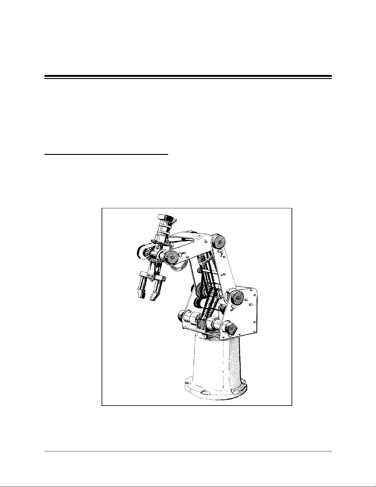
The SCORBOT-ER 4pc was designed and developed to emulate an industrial robot.
The open structure of the robot arm allows students to observe and learn about its internal
mechanisms.
1
Figure 1: SCORBOT-ER 4pc Robot Arm
User’s Manual 1 SCORBOT-ER 4pc
9810
Page 8

Acceptance Inspection
The robot arm and its controller are packed in two separate cartons. Save the original
packing materials and shipping carton. You may need them later for shipment or storage.
After removing the robot arm from its shipping cartons, examine it for signs of shipping
damage. If any damage is evident, do not install or operate the system. Notify your
freight carrier and begin appropriate claims procedures.
The standard SCORBOT-ER 4pc package includes the following items:
•
SCORBOT-ER 4pc Robot arm
•
Power cable 100/110/220VAC
•
3 bolts for mounting robot; set of hex wrenches
•
SCORBOT-ER 4pc User’s Manual
Refer to the Controller-PC User’s Manual for information about the control unit’s
standard and optional components.
Make sure you have received all the items listed on the shipment’s packing list. If
anything is missing, contact your supplier.
SCORBOT-ER 4pc 2 User’s Manual
9810
Page 9
Repacking for Shipment
Be sure all parts are back in place before packing the robot.
ò The robot should be repacked in its original packaging for transport.
If the original carton is not available, wrap the robot in plastic or heavy paper. Put the
wrapped robot in a strong cardboard box at least 15 cm (about 6 inches) longer in all
three dimensions than the robot. Fill the box equally around the robot with resilient
packing material (shredded paper, bubble pack, expanded foam chunks).
Seal the carton with sealing or strapping tape. Do not use cellophane or masking tape.
Handling Instructions
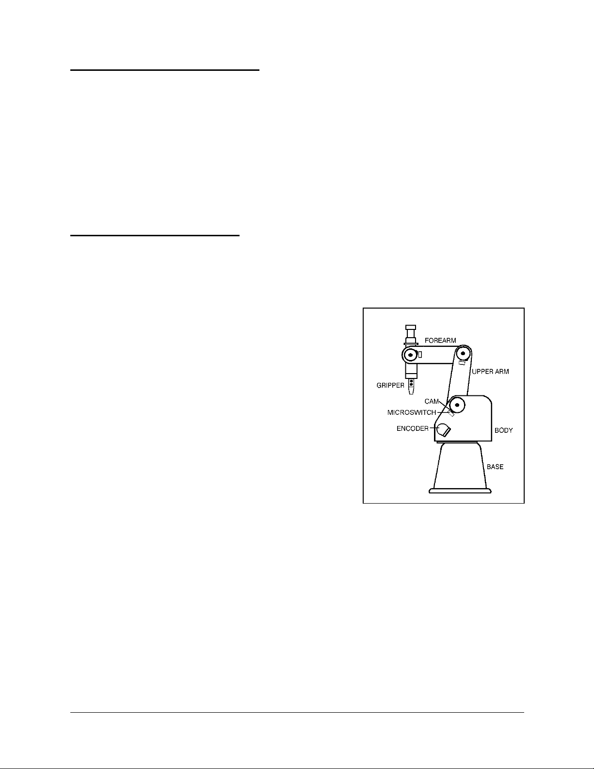
Lift and carry the robot arm only by grasping the body or the base.
See Figure 2.
Do not lift and/or carry the robot arm by its gripper,
upper arm or forearm.
Do not touch the microswitches, cams or encoders.
Figure 2: Robot Arm Parts
User’s Manual 3 SCORBOT-ER 4pc
9810
Page 10

CHAPTER
2
Specifications
This chapter includes the specifications the SCORBOT-ER 4pc robot arm and
descriptions of its components.
SCORBOT-ER 4pc Specifications
Mechanica l S tru c tu re Vertical articulated
Number of Axes 5 axes plus servo gripper
Axis Movement
Axis 1: Base rotation
Axis 2: Shoulder rotation
Axis 3: Elbow rotation
Axis 4: Wrist pitch
Axis 5: Wrist roll
Maximum Operating Radius 610mm (24.4")
End Effector
Maximum Gripper Opening
Hard Home
Feedback Optical encoder on each axis
Actuators 12VDC servo motors
Motor Capacity (axes 1–6)
Gear Ratios
Transmission Gears, timing belts, lead screw
Maximum Payload 1 kg (2.2 lb.), including gripper
Position Repeatability
Weight 11.5 kg (25 lb)
Maximum Path Velocity 600 mm/sec (23.6"/sec)
Ambient Operating Temperature 2°–40°C (36°–104°F)
310°
+130°
130°
±
130°
±
Unlimited (mechanically); ±570° (electrically)
DC servo gripper, with optical encoder,
parallel finger motion;
Measurement of object’s size/gripping force
by means of gripper sensor and software.
75 mm (3") without rubber pads
65 mm (2.6") with rubber pads
Fixed position on each axis,
found by means of microswitches
15 oz. in Peak Torque (stall)
70 W Power for Peak To rq u e
Motors 1, 2, 3: 127.1:1
Motors 4, 5: 65.5:1
Motor 6 (gripper) 19.5:1
0.2 mm (0.008") at TCP (tip of gripper)
±
/ –
35°
SCORBOT-ER 4pc 4 User’s Manual
9810
Page 11
Structure
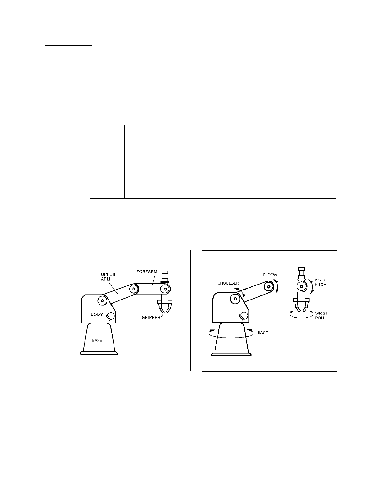
The SCORBOT-ER 4pc is a vertical articulated robot, with five revolute joints. With
gripper attached, the robot has six degrees of freedom. This design permits the end
effector to be positioned and oriented arbitrarily within a large work space.
Figures 3 and 4 identify the joints and links of the mechanical arm.
The movements of the joints are described in the following table:
Axis No. Joint Name Motion Motor No.
1
2
3
4
5
Base Rotates the body.
Shoulder Raises and lowers the up pe r ar m .
Elbow Raises and low ers th e fo re ar m .
Wrist Pitch Raises and lowers the end effector (gripper).
Wrist Roll Rotates the end effector (gripper).
1
2
3
4+5
4+5
Figure 2-3: Robot Arm Links
User’s Manual 5 SCORBOT-ER 4pc
9810
Figure 2-4: Robot Arm Joints
Page 12
Work Envelope
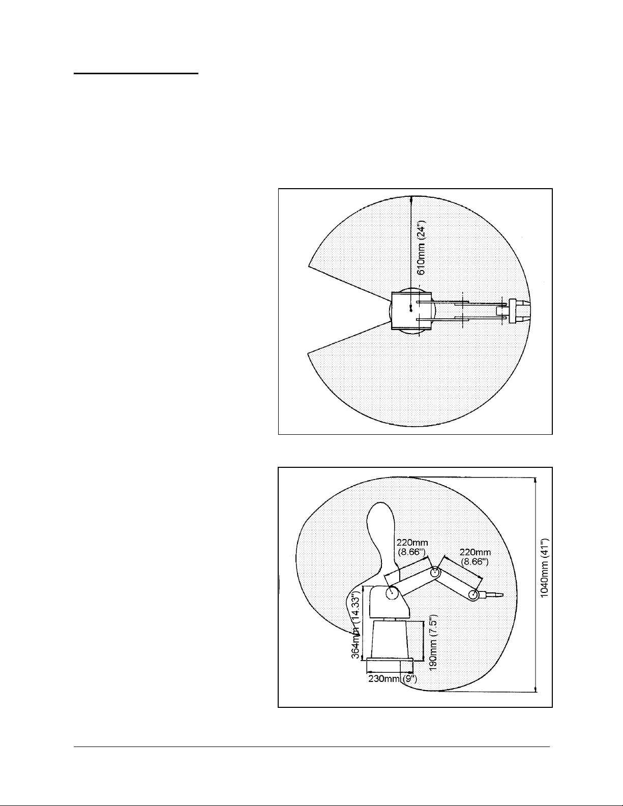
The length of the links and the degree of rotation of the joints determine the robot’s work
envelope. Figures 5 and 6 show the dimensions and reach of the SCORBOT-ER 4pc.
The base of the robot is normally fixed to a stationary work surface. It may, however, be
attached to a slidebase, resulting in an extended working range.
Figure 5: Operating Range (Top View)
Figure 6: Operating Range (Side View)
SCORBOT-ER 4pc 6 User’s Manual
9810
Page 13
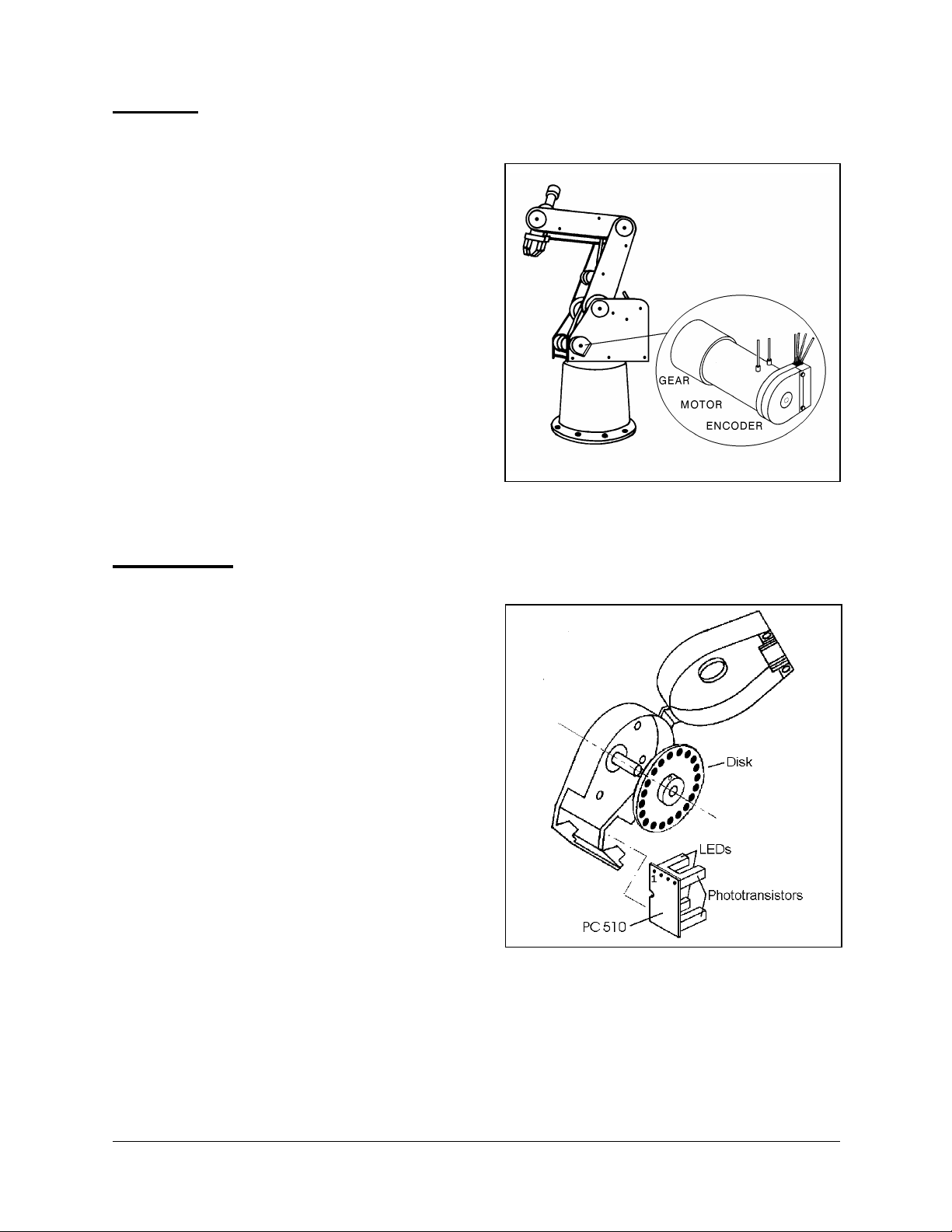
Motors
The robot’s five axes and gripper are
operated by DC servo motors. The
direction of motor revolution is
determined by the polarity of the operating
voltage: positive DC voltage turns the
motor in one direction, while negative DC
voltage turns it in the opposite direction.
Each motor is fitted with an encoder for
closed-loop control.
Figure 8: Motor
Encoders
The location and movement of each axis is
measured by an electro-optical encoder
attached to the shaft of the motor which
drives the axis.
When the robot axis moves, the encoder
generates a series of alternating high and
low electrical signals. The number of
signals is proportional to the amount of
axis motion. The sequence of the signals
indicates the direction of movement.
The controller reads these signals and
determines the extent and direction of axis
movement.
Figure 7: Encoder
User’s Manual 7 SCORBOT-ER 4pc
9810
Page 14
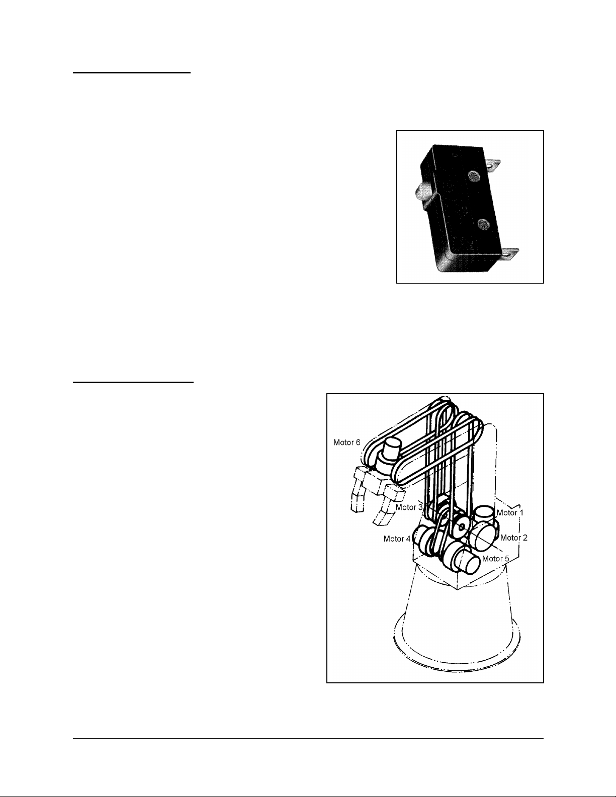
Microswitches
The SCORBOT-ER 4pc has five microswitches— one
on each axis—which serve to identify the robot’s home
position.
During the homing procedure, the robot joints are moved
one at a time. Each axis is moved until the its home
switch is activated. The axis is then moved slightly until
the the switch shuts off—at that point the joint is at home.
When all joints are at home, the robot is at home. This is
the point of reference for robot operation. Whenever the
system is turned on, the robot should be sent to this
position, by means of a software homing routine.
Figure 9: Microswitch
Transmissions
Several kinds of transmissions are used to
move the links of the robot arm.
•
Spur gears move the base and shoulder
axes.
•
Pulleys and timing belts move the elbow
axis.
•
Pulleys and timing belts, and a bevel
gear differential unit at the end of the
arm move the wrist pitch and roll axes.
•
A lead screw transmission opens and
closes the gripper.
Figure 10: Transmissions
SCORBOT-ER 4pc 8 User’s Manual
9810
Page 15
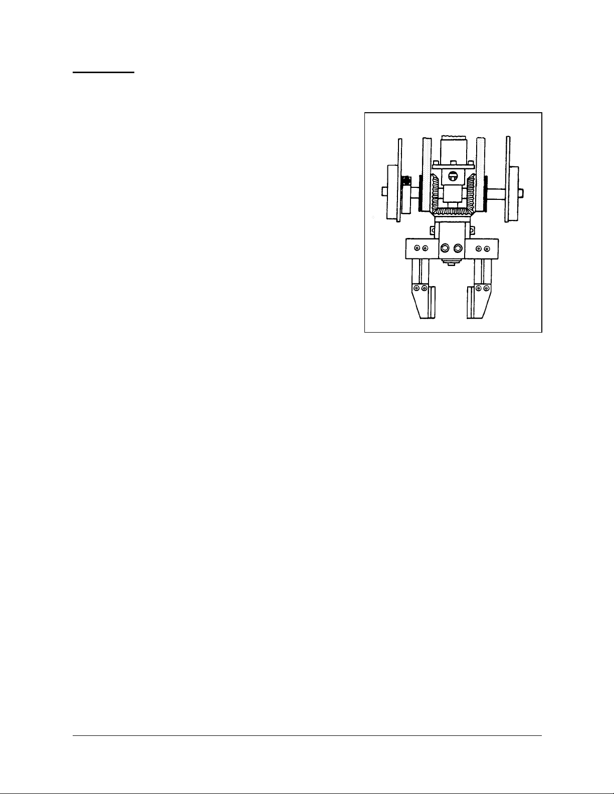
Gripper
The SCORBOT-ER 4pc has a servo jaw gripper
fitted with rubber pads. These pads can be removed
to allow the attachment of other end effector
devices, such as suction pads.
Three bevel gears form a differential gear train
which moves the wrist joint. When motors 4 and 5
are driven in opposite directions, the wrist pitch
moves up and down. When motors 4 and 5 are
driven in the same direction, the wrist rolls
clockwise and counterclockwise. A leadscrew
coupled directly to motor 6 causes the gripper to
open and close.
Figure 11: Gripper
User’s Manual 9 SCORBOT-ER 4pc
9810
Page 16

CHAPTER
3
Safety
This chapter contains important safety guidelines and warnings.
ò Read this chapter carefully before you attempt to install or use the robot system.
Precautions
This manual provides complete details for proper installation and operation of the
SCORBOT-ER 4pc. Do not install or operate the robot until you have thoroughly
studied this User’s Manual. Be sure you heed the safety guidelines for both the robot and
the controller.
1. Make sure the robot base is properly and securely bolted in place.
2. Make sure the robot arm has ample space in which to operate freely.
3. Make sure a guardrail, rope or safety screen has been set up around the
SCORBOT-ER 4pc operating area to protect both the operator and bystanders.
4. Do not enter the robot’s safety range or touch the robot when the system is in operation.
Before approaching the robot, make sure the motor switch on the controller front panel
has been shut off.
5. Make sure loose hair and clothing is tied back when you work with the robot.
ò To immediately abort all running programs and stop all axes of motion, press the
EMERGENCY STOP button on either the teach pendant or the control box.
SCORBOT-ER 4pc 10 User’s Manu al
9810
Page 17

Warnings
•
Do not install or operate the SCORBOT-ER 4pc under any of the following conditions:
•
Where the ambient temperature or humidity drops below or exceeds the specified
limits.
•
Where exposed to large amounts of dust, dirt, salt, iron powder, or similar
substances.
•
Where subject to vibrations or shocks.
•
Where exposed to direct sunlight.
•
Where subject to chemical, oil or water splashes.
•
Where corrosive or flammable gas is present.
•
Where the power line contains voltage spikes, or near any equipment which
generates large electrical noises.
•
Do not overload the robot arm. The combined weight of the workload and gripper
may not exceed 1kg (2.2 lb). It is recommended that the workload be grasped at its
center of gravity.
•
Do not use physical force to move or stop any part of the robot arm.
•
Do not drive the robot arm into any object or physical obstacle.
•
Do not leave a loaded arm extended for more than a few minutes.
•
Do not leave any of the axes under mechanical strain for any length of time.
Especially, do not leave the gripper grasping an object indefinitely.
•
Since the SCORBOT-ER 4pc motors are rated 12VDC nominal, while the controller
motor drivers supply 24VDC, do not drive axes continuously in one direction at
maximum speeds.
User’s Manual 11 SCORBOT-ER 4pc
9810
Page 18
CHAPTER
4
Installation
Before installing the SCORBOT-ER 4pc, be sure you have read and understood the
safety instructions and warnings detailed in Chapter 1.
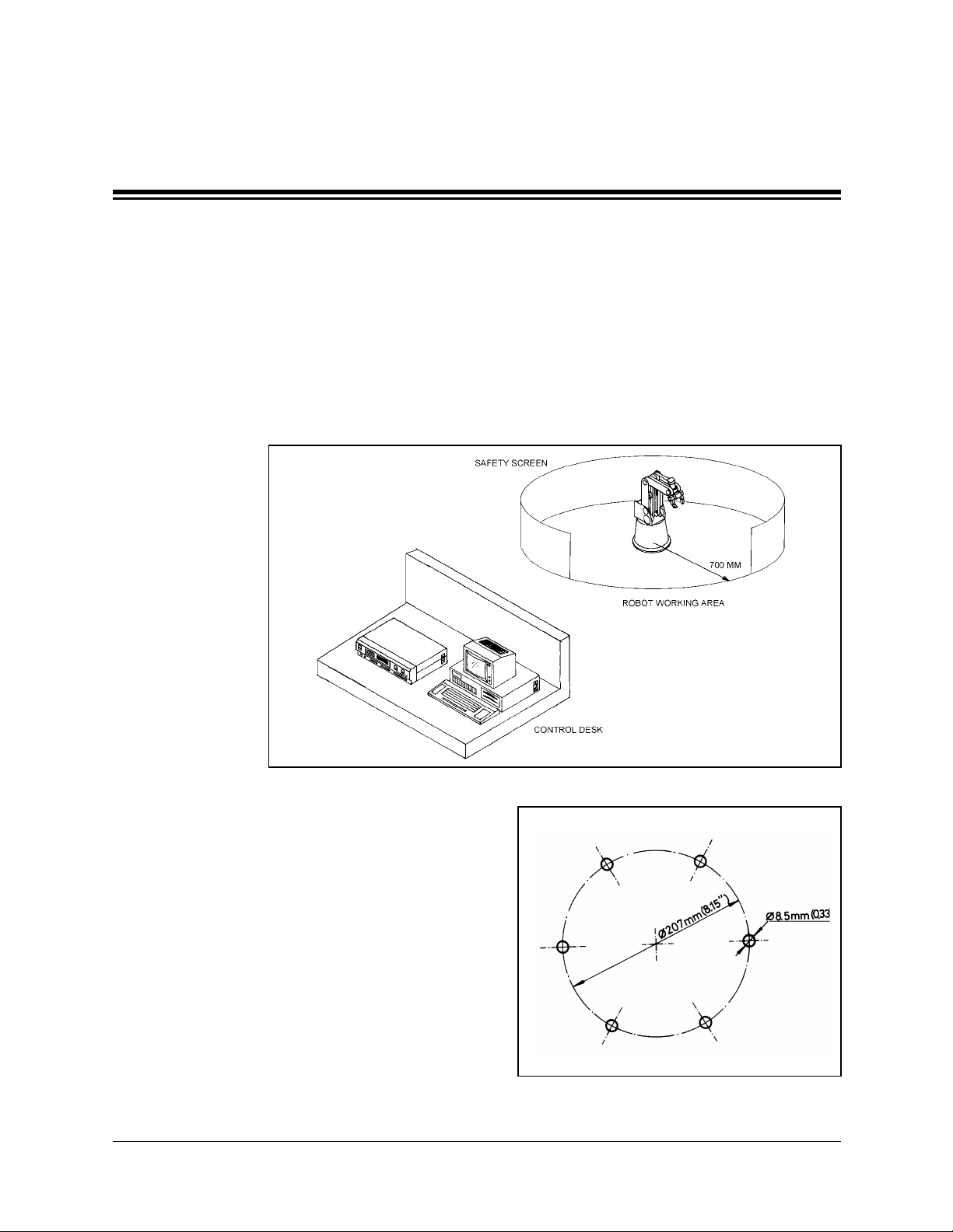
Be sure you have ample space to set up the robotic system, as shown in Figure 12.
1. Set up the SCORBOT-ER 4pc on a sturdy surface with a minimum 700mm of free
space all around the robot.
Figure 12: SCORBOT-ER 4pc Installation
2. Fasten the base of the robot arm to the work
surface with at least 3 bolts 120° apart, as
shown in Figure 13.
Robot Base
Pitch Circle
Hole (6 off)
Make sure the robot is securely bolted in
place. Otherwise the robot could become
unbalanced and topple over while in motion.
3. Set up a guardrail, rope or safety screen
around the robot’s operating area to protect
both the operator and bystanders.
SCORBOT-ER 4pc 12 User’s Manu al
∅
240 mm (9.49")
∅
207 mm (8.15" )
∅
8.5 mm (0.33")
Figure 13: Robot Base Plate Layout
9810
Page 19

4. Place the controller and computer on a sturdy surface at a safe distance from the
robot—well outside the robot’s safety range.
5. Connect the robot cable (D50 connector) to the SCORPOWER box.
6. Make sure all other connections have been made in accordance with the instructions in
the Controller-PC User’s Manual.
7. Turn on the computer and the SCORPOWER box.
User’s Manual 13 SCORBOT-ER 4pc
9810
Page 20

CHAPTER
5
Operating Methods
The SCORBOT-ER 4pc can be programmed and operated by means of SCORBASE
for Windows software and by a teach pendant. Software and teach pendant operation is
described fully in the other manuals supplied with the system.
SCORBASE for Windows Software
SCORBASE for Windows is a robotic control software package which has been
designed for use with the SCORBOT-ER 4pc. Its menu-driven structure and off-line
capabilities facilitate robotic programming and operation.
SCORBASE communicates with the robot controller by means of an RS232 channel.
SCORBASE for Windows can be operated in three levels, which are comparable to
Levels 1, 3 and 5 of the original DOS-based SCORBASE software. SCORBASE for
Windows Level 1 and Level 3 are recommended for those who wish to learn robotic
programming from the most basic stages. SCORBASEpro contains programming
commands and options for advanced users.
SCORBASE for Windows is described fully in the SCORBASE for Windows User’s
Manual.
Teach Pendan t
The teach pendant is an optional device.
The teach pendant is a hand-held terminal which is used for controlling the robot and
peripheral equipment connected to the same robot controller. The teach pendant is most
practical for moving the axes, recording positions, and sending the axes to recorded
positions. Other functions can also be executed from the teach pendant.
The Teach Pendant for Controller-PC User’s Manual fully describes the various
elements and functions of the teach pendant.
SCORBOT-ER 4pc 14 User’s Manu al
9810
Page 21

CHAPTER
6
Maintenance
Maintenance
The maintenance and inspection procedures detailed below will ensure continued
optimum performance of the SCORBOT-ER 4pc system.
Daily Operation
Perform a routine inspection of your system at the start of every working session, in the
following order:
1. Before you power on the system, check the following items:
•
The installation meets all safety standards.
•
The robot is properly bolted to the work surface.
•
All cables are properly and securely connected.
Cable connector screws are fastened.
•
No output is connected directly to a power supply.
•
No people are within the robot’s working range.
2. After you have switched on the PC and the control box, check the following items:
•
The power and motor LEDs on the control box light up.
•
No unusual noises are heard.
•
No unusual vibrations are observed in any of the robot axes.
•
There are no obstacles in the robot’s working range.
3. Bring the robot to a position near home, and activate the homing procedure. Check the
following items:
•
Robot movement is normal.
•
No unusual noise is heard when robot arm moves.
•
Robot reaches home position in every axis.
User’s Manual 15 SCORBOT-ER 4pc
9810
Page 22
Periodic Inspection
The following inspections should be performed regularly:
1. Visually check leads, cables and rubber components. Replace any cables which show
signs of abrasion or wear.
2. Check all bolts and screws in the robot arm using a wrench and screwdriver. Retighten as
needed.
3. Check all the tension of robot arm belts. When you press on a belt, the slack should be no
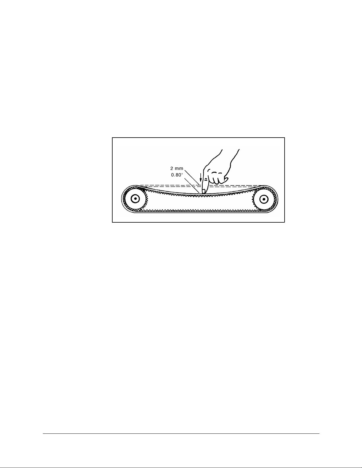
greater than 2mm (0.08"). Refer to Figure 14.
Figure 14: Belt Tension
Qualified Technician Only: Tighten the belts only if you are absolutely certain they are
slipping or retarding the motors. For complete information, refer to the section,
“Adjustments and Repairs,” later in this chapter.
4. Qualified Technician Only: Check for excessive backlash in the base axis. For complete
information, refer to the section, “Adjustments and Repairs,” later in this chapter.
SCORBOT-ER 4pc 16 User’s Manu al
9810
Page 23

Troubleshooting
ò The procedures in the section are intended only for technicians who have received
proper training and certification from the manufacturer.
Do not attempt to perform procedures for which you are not qualified.
Whenever you encounter a malfunction, try to pinpoint its source by exchanging the
suspected faulty component—for example, servo control card, control box, robot arm,
PC, cables—with an identical component from a working system.
Do not open the control box. There are no user-serviceable parts inside. Do not attempt
repairs for which you are not qualified. Contact your agent or an authorized technician
for repairs.
The following chart provides guidelines for identifying and rectifying problems which
you may encounter. Refer also to the Controller-PC User’s Manual for additional
troubleshooting instructions and information.
1. Controller functioning, but the robot cannot be activated.
•
Make sure an obstacle is not blocking the robot.
•
Make sure none of the axes has reached its mechanical limits.
•
Make sure the controller’s green MOTORS LED is lit.
•
Make sure the controller is in the Control Off state. Then activate the Control On
state from the PC or TP.
•
Make sure the robot cable is properly connected to the controller.
2. Robot does not find Home position in one or all of the axes.
•
Make sure the homing command was properly issued.
•
Make sure the robot cable is properly connected to the controller.
•
Make sure system homing parameters are properly set.
Make sure system homing parameters have not been erased.
•
Check the microswitch for this axis. Prepare and run a simple program to test the
microswitch (on axis 2 for example), as follows:
Set Variable LIMIT_SWITCH = 2
If Limit switch LIMIT_SWITCH jump to TURN_ON
turn off output LIMIT_SWITCH
Jump to END
TURN_ON:
turn on output LIMIT_SWITCH
END:
User’s Manual 17 SCORBOT-ER 4pc
9810
Page 24

•
Qualified Technician Only:
•
If the output LED does not turn on as expected (in the above software routine),
check the microswitch itself. Use a small screwdriver to press down on the
microswitch. You should hear it click and see it pop back up. If this does not
happen, the microswitch should be fixed or replaced.
•
If the microswitch has clicked, depress it again and, with an ohmmeter, check
whether the microswitch shorts its two poles.
•
If there is a short, depress the switch again and check the wires between the
microswitch and D50 connector.
•
If there is a short, depress the switch and check the two microswitch pins in the
D50 connector. (Refer to Chapter 8 for wiring and pin information).
3. One axis turns constantly in one direction.
•
Press and release the SCORPOWER Emergency button to reset the controller. Then
give the command to home the robot.
4. One of the axes or gripper does not respond, or does not function properly.
•
Make sure you have performed all steps in Item 1 and Item 2.
•
Turn the SCORPOWER control box off, then on again.
•
Check the encoder. To display encoder readings, select View|Encoders.
Enter the command Control Off (to disable servo control) and then physically move
the axis in question in both directions. The encoder reading should rise for rotation in
one direction and fall for rotation in the opposite direction.
If the encoder readings do not change, the problem is caused by a faulty encoder, a
break in the encoder wiring, or a faulty connection on a PCB within the robot.
SCORBOT-ER 4pc 18 User’s Manu al
9810
Page 25
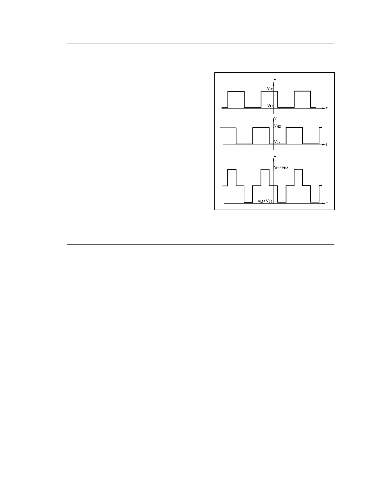
5. Errors in the accuracy of the robot. Controll er d oes no t r ead the enc ode r, or f ail s t o sh ow
changes in encoder readings.
Qualified Technician Only:
•
Using an oscilloscope, check the signals (P
0
and P1) received from the encoder’s two
phototransistors. Figure 15 shows the wave
diagrams which emanate from the two
channels of the encoder (P0 and P1) with
respect to the time axis. The top two signals
should be clean square waves:
8."*NQY+"XCNWG"UJQWNF"DG"2068"QT"NGUU0
8
"*JKIJ+"XCNWG"UJQWNF"GZEGGF"6"80
*
In addition, check the third wave, which
shows the sum of the two waves. The
diagram reflects a time shift of a quarter
cycle between the two waves.
If the waves are distorted with an incorrect
shift between them, the encoder is faulty and
Figure 15: Encoder Signals
should be adjusted or replaced.
6. Errors in the repeatability of the robot.
Qualified Technician Only:
•
Try to identify the faulty axis. If many or all axes are faulty, look for an electrical
noise source in your environment.
•
Check the encoder. Follow the procedures in Item 3 and Item 4.
•
If no problem found by means of Items 8 and 9, do the following:
•
Bring the robot to a starting position. Using a pencil, draw a fine, continuous line
on the robot which crosses from one link to the adjacent link at the joint in question.
5GNGEV"8KGY^'PEQFGTU"VQ"FKURNC["VJG"GPEQFGT"TGCFKPIU0
'PVGT"VJG"EQOOCPF"%QPVTQN"1HH"*VQ"FKUCDNG"UGTXQ"EQPVTQN+0
2J[UKECNN["OQXG"VJG"CZKU"VQ"CPQVJGT"RQUKVKQP0"6JGP"TGVWTP"VQ"VJG"UVCTVKPI
RQUKVKQP"OCTMGF"D["VJG"NKPG"[QW"FTGY0"%JGEM"VJG"GPEQFGT"TGCFKPI"HQT"VJG"CZKU
CICKP0"+V"UJQWNF"DG"YKVJKP"UGXGTCN"EQWPVU"QH"VJG"HKTUV"TGCFKPI0"4GRGCV"VJKU"UVGR
C"PWODGT"QH"VKOGU0"+H"VJG"GTTQT"KP"VJG"GPEQFGT"TGCFKPI"CEEWOWNCVGU."VJG
GPEQFGT"PGGFU"VQ"DG"TGRNCEGF0
•
Check the transmission for loose points or damage. Check for continuity of
movement in all the relevant transmission components (gears and belts moving
together with the drive shaft of the motor).
User’s Manual 19 SCORBOT-ER 4pc
9810
Page 26

7. Gripper opens and closes too freely; weak gripping force; or the gripper motor rotates
endlessly.
Qualified Technician Only:
•
The Oldham coupling in the gripper assembly is loose. Follow the instructions in the
section, “Adjustments and Repairs,” later in this chapter.
•
Alternately, the gripper gear is broken, and must be replaced.
8. Too much freedom (backlash) in the base axis.
Qualified Technician Only:
•
Refer to the section, “Adjustments and Repairs,” later in this chapter.
9. Unusual noise.
Qualified Technician Only:
•
Loose screws.
•
Poor lubrication.
•
Worn motor brushes.
•
Worn timing belt.
SCORBOT-ER 4pc 20 User’s Manu al
9810
Page 27
Adjustments and Repairs
ò These procedures are to be performed only by a qualified technician who has received
proper training and certification from the manufacturer.
Adjusting the Timing Belts
Qualified Technician Only
When you check the tension of robot arm belts, as indicated in Figure 8-1 at the
beginning of this chapter, the slack should be no greater than 2mm (0.08"). Tighten the
belts only if you are absolutely certain they are slipping or retarding the motors.
•
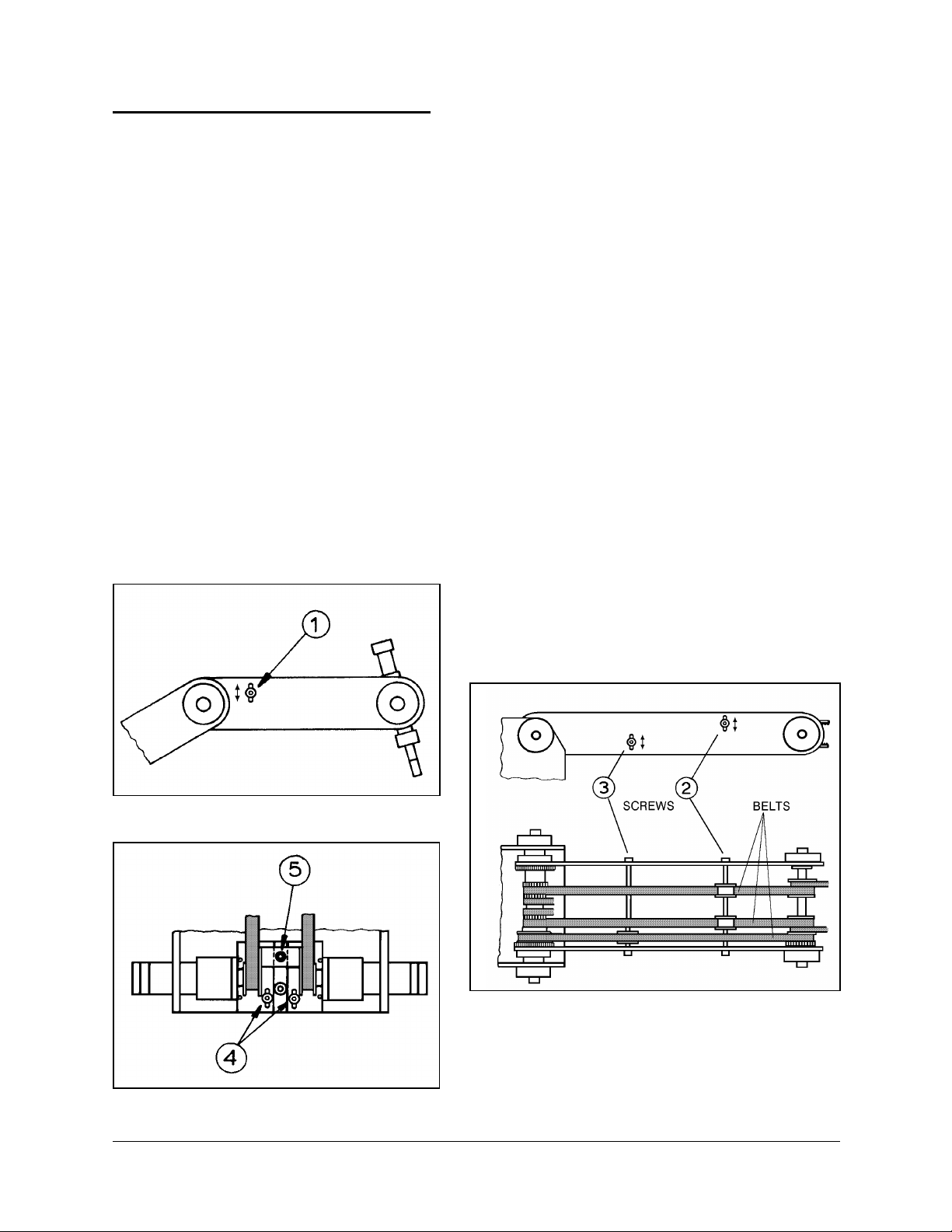
Figure 16 shows how to tighten the belts in the forearm which move the wrist axes
(pitch and roll). Loosen the two screws (1) which hold the tension shaft. Press down
on the shaft and retighten the screws.
•
Figure 17 shows how to tighten the belts in the upper arm which move the wrist axes
(2), and the belt which moves the elbow axis (3).
•
Figure 18 shows how to tighten the two belts in the robot base which move the wrist
axes. First, loosen the screw (5), and then loosen either one or both screws (4). Then,
to tighten the belts, simultaneously pull the appropriate motor and retighten screw(s)
(4). Finally, retighten screw 5.
Figure 16: Tightening Belts in Forearm
Figure 17: Tightening Belts in Upper Arm
Figure 18: Tightening Belts in Robot Base
User’s Manual 21 SCORBOT-ER 4pc
9810
Page 28
Adjusting Base Anti-Backlash
Qualified Technician Only
Refer to the exploded views of the robot in Figures 22 and 23.
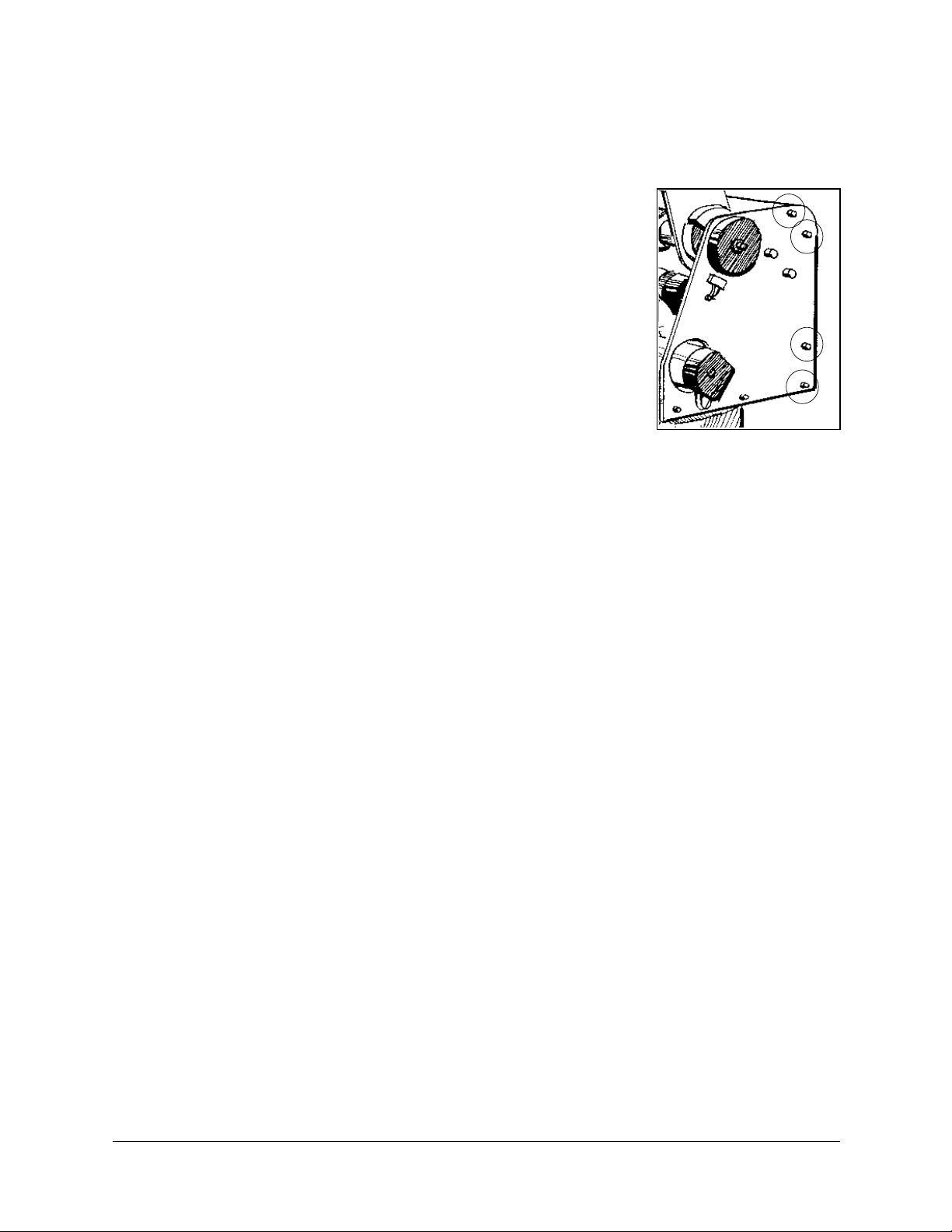
1. Refer to Figure 19. Remove the shoulder cover:
•
Remove the top three screws on each side of the shoulder
cover.
•
Loosen (or remove) the bottom screw on each side.
2. Refer to Figure 23. Remove the base lock nut (S286).
3. Refer to Figure 22.
•
Remove the two socket head cap screws (S19), and detach
the base motor from the base plate (12).
•
Check the set screw (S151) that holds the spur gear (S25) to
the base motor gear (S309). If it is loose, tighten it.
•
Reattach the base motor to the base plate.
4. Refer to Figure 22. The anti-backlash unit has four gears. Two gears (22 and 27) are on
top of one other with a spring (23) fitted in between. Stretch the anti-backlash spring in
the base transmission:
•
Make sure the robot is bolted in place.
•
Remove the outermost gear (20). The gear (22) is now free. Note the small unused
hole on the base plate near the gears (22 and 27). It will enable you to lock the gear
(22) in the next step.
•
To prevent the gear (22) from moving during the following steps, lock the gear by
inserting a short pin through this hole and into a groove in this gear. Make sure the
pin does not touch the gear (27) and that the gear (27) is free to rotate.
•
Mark the two teeth which are directly above one another on the gears (22 and 27),
one on the upper gear and one on the lower gear.
•
Manually turn the robot counterclockwise a distance of six teeth between the marked
teeth. The spring should now be correctly stretched.
•
Return the gear (20) to its position and fasten the screw.
•
Remove the locking pin.
Figure 19: Shou ld er
Cover Screws
5. Replace the base lock nut (S286).
6. Replace the shoulder cover.
SCORBOT-ER 4pc 22 User’s Manu al
9810
Page 29

Tightening the Oldham Coupling in Gripper
Qualified Technician Only
Refer to the exploded view of the gripper assembly in Figure 20.
Gripper Disassembly
1. Remove the gripper motor (S312) from the plate (112) by unscrewing the three bolts
(2 bolts S12 and one bolt S14). The Oldham coupling (S313) has three parts—two metal
parts fitted with bolts and an intermediate plastic part. When you remove the motor, one
metal piece of the coupling stays attached to the shaft. The second metal piece of t he
coupling stays attached to the lead screw (94). The plastic piece remains attached to either
one of the two metal pieces.
2. Remove the lead screw (94) from within the shaft (105) by turning it counterclockwise.
3. Fasten both metal pieces to their respective shafts by firmly tightening the Allen screws
(one piece to the motor output shaft; the other to the lead screw.)
Note: When tightening the coupling piece to the motor output shaft, make sure the
coupling is 1.5mm to 2mm away from the plate (112).
Gripper Reassembly
1. Make sure the coupling’s plastic piece is attached to the metal piece attached to the lead
screw (94). Keep the gripper fingers closed. Screw the lead screw (94) with the coupling
piece attached, clockwise into the shaft (105), as tightly as possible. Now release the
gripper fingers.
2. Refit the motor by aligning the coupling fitted to the motor output shaft together with the
plastic coupling piece attached to the metal piece attached to the lead screw (94).
3. When all the coupling sections are aligned and attached, turn the motor body until the
holes in the plate (112) align with those in the gear motor support (91). Reinsert and
tighten the three bolts which you removed at the beginning of the procedure.
User’s Manual 23 SCORBOT-ER 4pc
9810
Page 30

CHAPTER
7
Parts Lists
This chapter contains isometric drawings of the robot arm.
Note that the SCORBOT-ER 4pc robot arm has several enhanced features which do not
appear in these drawings. They are:
•
Improved encoders on all motors provide greater accuracy. The encoder disk has 20
slots; the encoder housing and circuitry have also been upgraded.
•
Motor supports (items 34 and 35) for the shoulder and elbow axes have been
improved; their dimensions have changed, and counter bearings have been added, to
increase strength and stability.
•
Plates have been added to the robot arm frame, across the forearm and upper arm, and
around the shoulder, to increase strength and stability.
SCORBOT-ER 4pc 24 User’s Manu al
9810
Page 31

Dwg # Cat # Description
1 113012 Bearing housing cover (plastic)
2 111401 Main shaft base
S 2 306003 Socket head cap screw #4-40 X 1/4
S 3 306004 Socket head cap screw #4-40 X 3/8
4 113004 Base plate
5 113001 Base
S 6 306201 Socket head cap screw #6-32 X 1/4
S 8 306002 Socket head cap screw #2-56 x 3/8
11 111906 Spur gear (120 teeth)
S 11 306204 Socket head cap screw #8-32 x 1/4
12 112103 Bottom Plate - shoulder
S 12 301205 Socket head cap screw #8-32 x 3/8
S 13 306206 Socket head cap screw #8-32 x 1/2
S 14 306207 Socket head cap screw #8-32 x 5/8
15 112401 Support base - motors 4+5
16 112403 Support clamp - motors 4+5
17 110205 Right side plate - shoulder
18 110210 Left side plate - shoulder
S 18 306401 Socket head cap screw #10-32 x 3/8
S 19 306402 Socket head cap screw #10-32 x 1/2
20 111901 Anti-backlash spur gear (transfer)
S 20 306404 Socket head cap screw #10-32 x 3/4
S 21 306405 Socket head cap screw #10-32 x 7/8
22 111902 Anti-backlash spur gear (upper)
S 22 306407 Socket head cap screw #10-32 x 1/4
23 113501 Anti-backlash spring
S 23 306403 Socket head cap screw #10-32 x 5/8
24 107003 Washer
S 24 306408 Socket head cap screw #10-32 x 11/2
S 25 321001 Ball bearing (motor 1 gear)
S 26 306602 Socket head cap screw #1/4-20 x 1
27 111903 Anti-backlash spur gear (base)
S 27 306602 Socket head cap screw #1/4-20 x 5/8
28 111907 Spur gear (base motor)
S 31 306414 Socket head cap screw #10-32 x 3/4 x 1/4 shoulder
32 319404 Spur gear (motors 2+3)
34 112405 Motor support (motor 2) [differs in ER 4pc]
35 112404 Motor support (motor 3) [differs in ER 4pc]
37 112402 Motor support (motors 4+5)
38 319406 Timing belt pulley (motors 4+5)
40 111606 Rear cross bar [not used in ER 4pc]
46 111402 Main shoulder shaft
47 111909 Timing belt pulley
48 111911 Timing belt pulley
User’s Manual 25 SCORBOT-ER 4pc
9810
Page 32

Dwg # Cat # Description
49 111905 Spur gear (72 teeth)
52 111405 First tension shaft
53 113013 Tension wheel
55 111406 Second tension shaft
56 113014 Tension pulley
57 112406 Clamp – lower arm – left side plate
58 110215 Upper arm – right side plate
60 111904 spur gear (right – 72 teeth)
61 110220 Upper arm – left side plate
63 112407 Clamp – lower arm – left side plate
64 111403 Middle shaft
67 107001 Aluminum spacer
70 111910 Timing belt pulley
S 70 306007 Flat head socket screw #4-40 x 1/4
72 111407 Third tension shaft
74 111404 Gripper axis
76 112439 Stopper (motors 4+5)
77 110705 Base plate limit switch
S 81 306201 Flat head socket screw #8-32 x 3/8
82 113008 Timing belt pulley + miter gear
S 82 306211 Flat head socket screw #8-32 x 1/2
84 110228 Forearm left side plate
86 111912 Timing belt pulley
87 112114 Flange
S 87 306410 Flat head socket screw #10-32 x 1/2
88 110223 Forearm – right side plate
91 112408 Gripper gear motor support
S 91 306412 Flat head socket screw #10-32 x 1/4
94 113801 Lead screw
96 112117 Gripper bridge
97 112118 Gripper finger (inner)
98 112119 Gripper finger (outer)
99 112120 Gripper finger (short)
100 112113 Gripper clamp
101 110703 Mounting plate – gripper
102 113201 Rubber pad – gripper
103 111409 Pivot pin
105 111408 Main shaft – gripper
107 113802 Lead nut – gripper
108 112115 Bearing housing
109 112116 Bearing housing cover
112 110229 Gripper motor base plate
113 113505 Spring 120 g. (gripper motor) [not used in ER 4pc]
S 115 45007 Encoder circuitry (3 slots) [differs in ER 4pc]
SCORBOT-ER 4pc 26 User’s Manu al
9810
Page 33

Dwg # Cat # Description
116 113009 Miter gear (bottom)
S 116 45006 Encoder circuitry (6 slots) [differs in ER 4pc]
127 107009 Spacer washer (for base bearing)
S 139 306008 Socket head set screw #4-40 x 1/8
S 145 306213 Socket head set screw #8-32 x 3/16
S 151 306413 Socket head set screw #10-32 x 3/16
S 153 306214 Socket head set screw #8-32 x 1/4 (without head)
S 187 302002 Socket binding head screw M2 x 10 (limit switch)
S 188 302001 Slotted binding head screw M2 x 8 (limit switch)
S 189 302006 Slotted bindi n g h e a d scr e w M2x20 (encoder housing)
S 206 313001 Washer (for screw #4-40)
S 207 107012 Washer (black); internal; for plastic cover ∅ 12.5 x ∅ 5.5 x 0.6
S 208 313004 Washer for screw #10-32
S 209 313005 Washer for screw ∅1/4
S 212 314508 Washer lock; black; external ∅ 5
S 215 314002 Spring washer (for screw #4-40)
S 216 314003 Spring washer (for screw #6-32)
S 217 314004 Spring washer (for screw #8-32)
S 218 314005 Spring washer (for screw #10-32)
S 219 314006 Spring washer (for screw ∅ 1/4)
S 225 314503 Lock washer M2
S 227 313003 Washer (for screw #8-32)
S 232 107008 Teflon washer ∅ 1/4" x ∅ 3/8" x 0.6mm
S 233 107007 Teflon washer ∅ 1/4" x ∅ 1/2" x 0.6mm
S 234 113016 Nylon washer ∅ 11 x ª 4 [not used in ER 4pc]
S 240 310001 Hexagonal nut M2
S 253 316006 E-Ring ∅ 1/8 DIN 6799
S 254 316003 Retaining ring ∅ 10 DIN 471
S 255 316004 Retaining ring ∅ 12 DIN 471
S 257 316302 Retaining ring ∅ 25 DIN 471
S 260 320005 Ball bearing ∅ 8 x ∅ 22 x 7
S 261 320004 Ball bearing ∅ 10 x ∅ 19 x 5
S 262 320006 Ball bearing ∅ 10 x ∅ 26 x 8
S 263 320203 Ball bearing ∅ 25 x ∅ 47 x 8
S 268 320701 Needle bearing ∅ 12 x ∅ 16 x 10
S 269 320702 Needle bearing ∅ 12 x ∅ 19 x 16
S 270 320704 Needle bearing ∅ 15 x ∅ 21 x 12
S 270 320705 Bushing for #320704
S 275 320501 Thrust bearing ∅ 10 x ∅ 24 x 2
S 276 320502 Thrust washer ∅ 10 x ∅ 24 x 1
S 277 320503 Thrust washer ∅ 10 x ∅ 24 x 2.5
S 278 320504 Thrust bearing ∅ 12 x ∅ 26 x 2
S 279 320505 Thrust washer ∅ 12 x ∅ 26 x 1
S 283 314501 Lock washer
User’s Manual 27 SCORBOT-ER 4pc
9810
Page 34

Dwg # Cat # Description
S 285 310401 Lock nut – gripper
S 286 310402 Lock nut – base KM 5
S 288 100706 Washer ∅ 10.5 x ∅ 20 x 0.5
S 289 100705 Washer ∅ 12.5 x ∅ 22 x 0.5
S 293 319201 Timing belt
S 294 319202 Timing belt
S 295 319203 Timing belt
S 300 315202 Flange – timing belt pulley
S 301 315201 Flange – timing belt pulley
S 308 317501 Pivot pin ∅ 1/8" x 3/8"
S 309 430901 Motor Gear - base; 127.7:1
S 310 430901 Motor Gear - shoulder/elbow; 127.7:1
S 311 430902 Motor Gear - pitch/wrist 65.5:1
S 312 430903 Motor Gear - gripper
S 313 319001 Coupling
S 315 410802 Limit switch
S 316 310802 Nut for harness
S 317 300006 Harness clamp
S 318 113006 Rubber plug (base)
S 319 300007 Harness clamp
S 320 314007 Conical washer
S 322 113203 Rubber grommet
S 324 113202 O-ring (rubber)
S 325 113204 Rubber stopper
S 350 317801 Roll pin ∅ 1/8 x 1 1/4
S 351 317502 Ball bearing ∅ - 3.5 mm
414 105001 Encoder disk (3 slots) - gripper [differs in ER 4pc]
427 113005 Encoder housing (plastic) [differs in ER 4pc]
429 105002 Encoder disk (6 slots) [differs in ER 4pc]
SCORBOT-ER 4pc 28 User’s Manu al
9810
Page 35
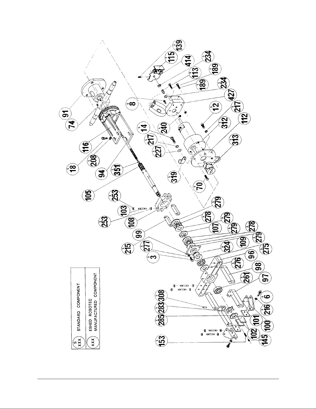
Figure 20: Gripper Assembly
User’s Manual 29 SCORBOT-ER 4pc
9810
Page 36
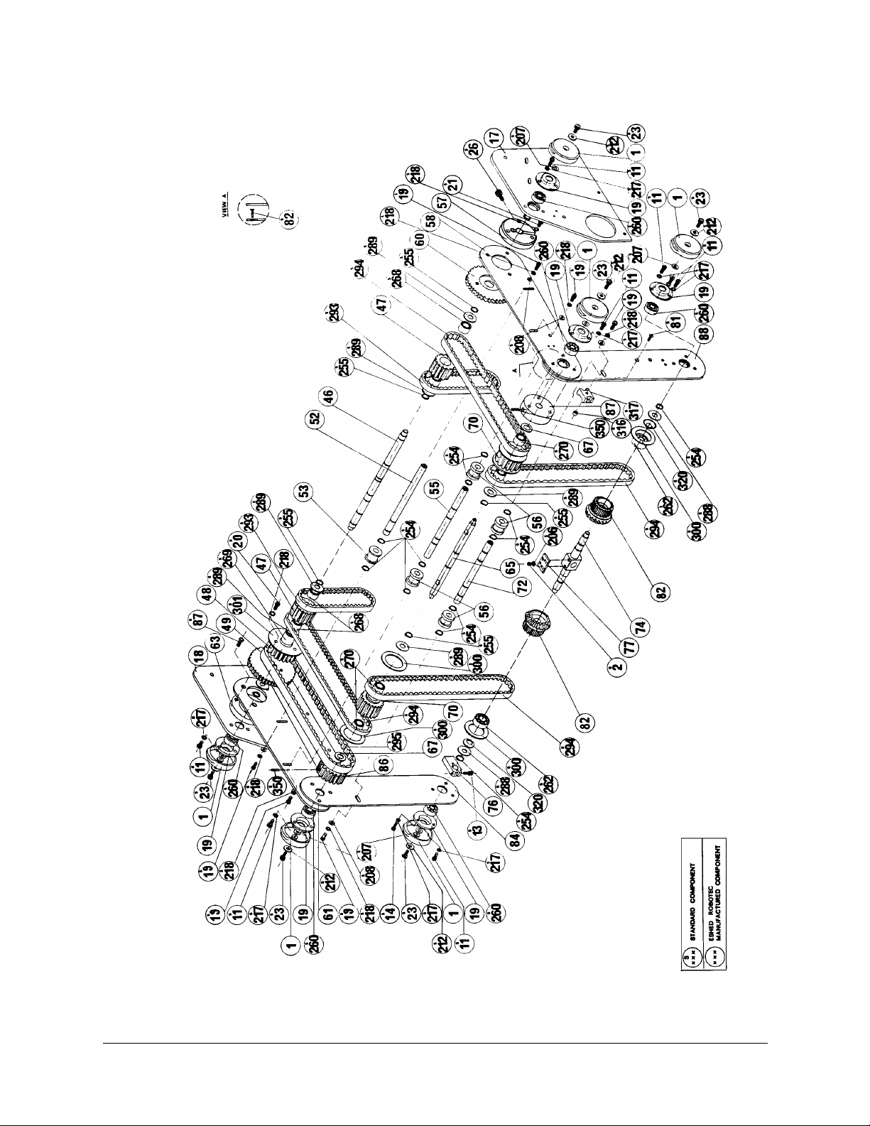
Figure 21: Robot Arm Assembly
SCORBOT-ER 4pc 30 User’s Manu al
9810
Page 37
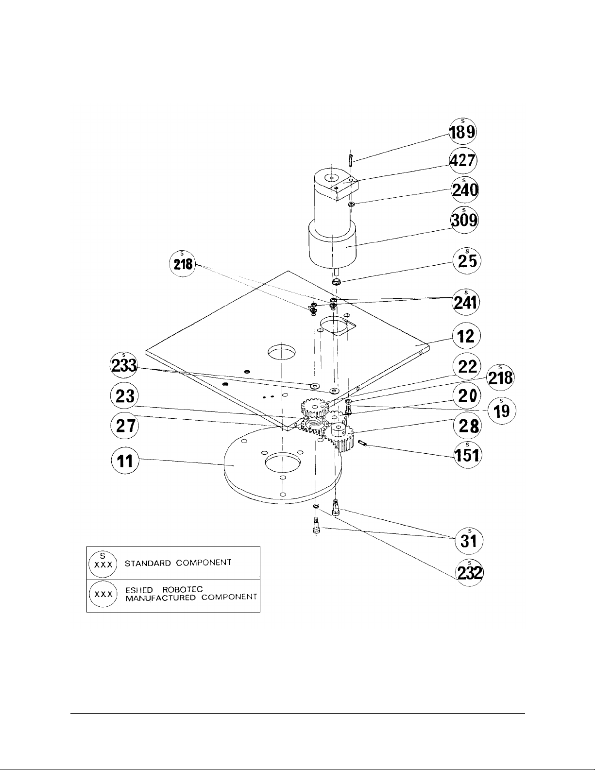
Figure 22: Anti-Backl ash Ass emb ly
User’s Manual 31 SCORBOT-ER 4pc
9810
Page 38
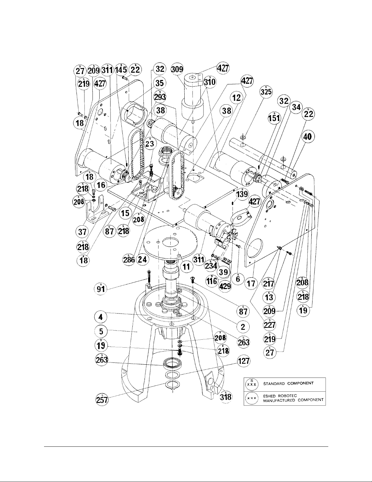
Figure 23: Base and Motors Assembly
SCORBOT-ER 4pc 32 User’s Manu al
9810
Page 39
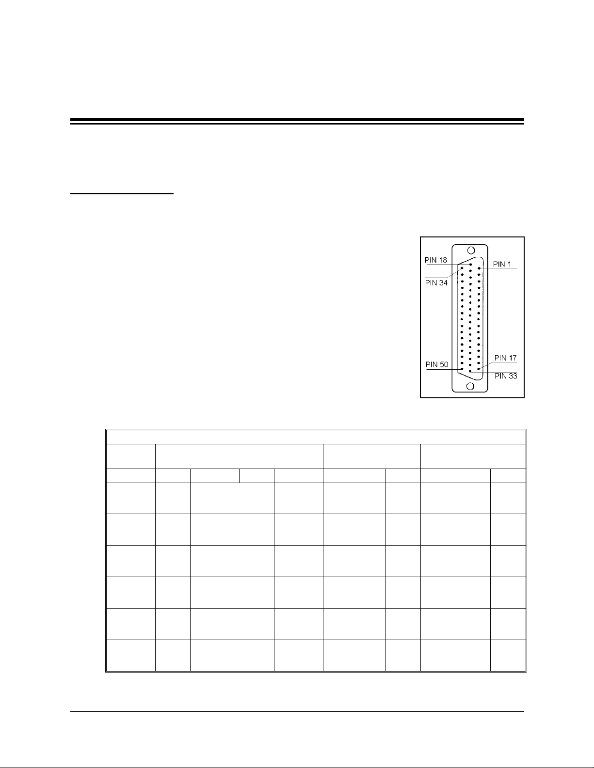
Robot Wiring
The robot is connected to the Controller-PC by means of a cable
which runs from the robot base to the D50 connector marked
ROBOT
The leads from the five motors on the robot body and their
encoders are connected directly to the D50 connector on the robot
cable. The leads from the gripper motor and the microswitches on
the arm reach the D50 connector via a square 12-pin Molex
connector in the base of the robot; these leads are particularly
flexible and resistant to breakage, even after extensive movement
of the robot arm.
on the rear panel of the SCORPOWER box.
CHAPTER
Wiring
8
The following table details the wiring for the various electrical
components in the
SCORBOT-ER 4p c
(* indicates two wires on same pin.)
Robot Arm Signal
Axis Motor Encoder Pad # Microsw. Color Pin# Color Pin #
1
2
3
4
5
Gripper
+
–
+
–
+
–
+
–
+
–
+
–
robot.
SCORBOT-ER 4pc Wiring
Lead to Molex
12-pin Connector
gray
yellow
Figure 24:
Robot D50 Connector
Lead to
D50 Connector
white
gray/green
white
white/green
white
orange/brown
white
orange/green
white
orange/gray
white
8
orange/blue
7
50
17
49
16
48
15
47
14
46
13
45
12
User’s Manual 33 SCORBOT-ER 4pc
9810
Page 40

SCORBOT-ER 4pc Wiring
Robot Arm Signal
Axis Motor Encoder Pad # Microsw. Color Pin# Color Pin #
Lead to Molex
12-pin Connector
Lead to
D50 Connector
GND 1 white 33*
P
1
1
V
LED
P
0
3 white/gray 5
2 yellow 11
4 brown 2
GND 1 white 32*
P
2
1
V
LED
P
0
3 white/orange 21
2 yellow 27
4 gray 1
GND 1 white 31*
P
3
1
V
LED
P
0
3 brown/blue 4
2 yellow 10
4 green 36
GND 1 white 30*
P
4
1
V
LED
P
0
3 green/brown 20
2 yellow 26
4 orange 35
GND 1 white 29*
P
5
1
V
LED
P
0
3 green/blue 3
2 yellow 9
4 blue 18
GND 1 black 12 white 28*
Gripper
P
1
V
LED
P
0
3 green 11 gray/blue 19
2 yellow 10 white 25
4 brown 9 white/blue 34
GND white 33*
1
MS brown 23
GND white 32*
2
MS gray 7
GND white 1 white 31*
3
MS white 2 orange 24
GND blue 3 white 30*
4
MS blue 4 green 8
GND orange 5 white 29*
5
MS orange 6 blue 6
Gripper
no
connection
white 28*
brown/gray 22
SCORBOT-ER 4pc 34 User’s Manu al
9810
Page 41
Single Axis Wiring
In addition to the robot’s six motors, the Controller-PC can control two additional
motors (axes 7 and 8) which operate peripheral devices. These additional motors are
connected to the controller by means of D9 connector ports on the front of the
SCORPOWER box.
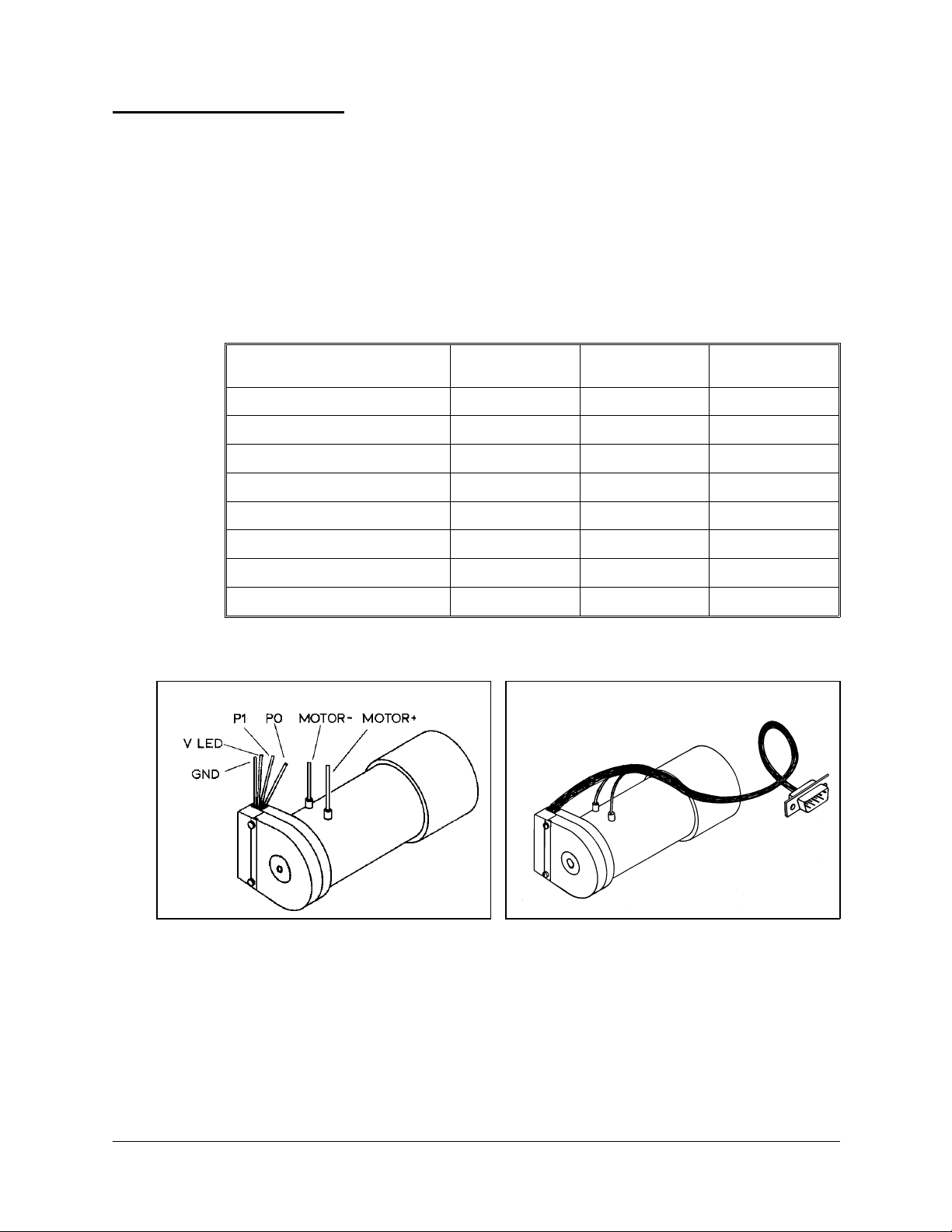
The following table details the wiring for a motor, encoder, and (optional) microswitch
when connected to the controller. Refer to Figures 25 and 26.
The last column in the table shows the colors of the leads used in the Motor Kit accessory.
Function
Motor Power (+)
Motor Power (–)
Encoder Phototransistor (P0)
Encoder Phototransistor (P1)
Encoder LED voltage (V
LED
Encoder Ground (GND)
Microswitch Signal (MS) *
Microswitch (GND) *
(PC510) Pad #
)
Encoder
4 8 brown
36white
2 3 yellow
1 5 + Shield black
D9 Connector
Pin #
1red
9 green
4 orange
5 orange
Motor Kit
Lead Color
Figure 25: Motor Wiring Figure 26: Motor with D9 Connector
User’s Manual 35 SCORBOT-ER 4pc
9810
 Loading...