

Art No 11319
All rights reserved. Reprinting,, also in excerpts, without prior permission of ESERA and E-Service GmbH prohibited. Technical changes
reserved. ESERA E-Service GmbH 2016
www.esera-automation.de 11319 Manual 1-Wire Controller 1 ETH V2.2 Page 1 von 4
Operating instructions
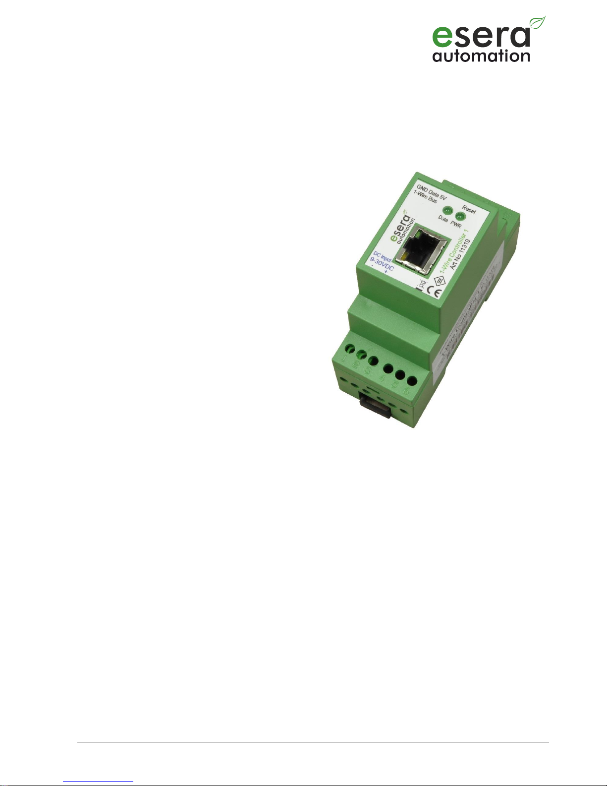
1-Wire Controller 1 Ethernet
1-Wire Controller 1 for independent
communication and updating of the 1-Wire
networks
Cyclical output of the processed 1-Wire data in
plain text
No 1-Wire driver (TMEX) necessary
Data logging in case of communication
interruption to the
host system (option)
Power supply for 1-Wire network
Designed for small up to large 1-Wire networks
Top-hat rail cases for the assembly of the
switchboard
Wide power voltage range
Management of all ESERA-Automation
1-Wire modules
1 Introduction
Before you start assembling the 1-Wire Controller 1 and before you take the device into operation, please read
these assembly and operating instructions carefully to the end, especially the section referring to the safety notes.
2 Product description
Independent management
The 1-Wire controller is designed for the independent management of a 1-Wire network. You no longer have to
worry about the 1-Wire commands or formulas in order to evaluate sensor data. The controller independently scans
the 1-Wire network for components (sensors and actuators) and will, depending on the found component, provide
the respective data output, readily converted in plain text.
Formatted data output
The 1-Wire controller ensures the cyclical output of readily processed sensor and actuator data, for instance for
temperature sensors in C°. Only a division by 100 is necessary. Additionally, the article number for ESERA modules
can be supplied, the calculation and the output occur adjusted to the function of the module.
Designed for all 1-Wire networks
The 1-Wire interface of the controller is specially designed to safely handle 1 Wire networks, from small ones up to
very large ones, with long cable sections. 1-Wire sensors can simultaneously be operated, miscellaneously, in
parasitic or normal mode. The currently most powerful 1 Wire interface was used, in order to ensure maximal data
safety for complex network structures as well.
System time / real time clock
Your system does not have a real time clock with battery buffering? No problem, the 1-Wire controller gladly
offers you the clock time with the date. A real time clock with battery buffering is integrated.
All rights reserved. Reprinting,, also in excerpts, without prior permission of ESERA and E-Service GmbH prohibited. Technical changes
reserved. ESERA E-Service GmbH 2016
www.esera-automation.de 11319 Manual 1-Wire Controller 1 ETH V2.2 Page 2 von 4
Power supply
In order to supply power, the 1-Wire controller has a wide range input of 9 - 30VDC and is thus equally suitable
for 12V power supplies and for typical industrial 24VDC power supplies.
You can find appropriate top-hat rail or wall power supplies in our webshop.
3 Software
The 1-Wire controller can be configured, steered and read out with every serial terminal software, per virtual COM
Port, UDP or TCP.
4 Technical data
Ethernet Interface: TCP/IP oder UDP
- 10/100 MBit Ethernet Interface (RJ45)
- Auto Negotiation (Full-duplex and Half-duplex)
- Auto MDI/MDIX
- Support für DHCP or fix IP-Adresse
- DNS Support
- Support User Password for Security
- DYN-DNS Server Support
Firmware Update: via ESERA Bootloader -Tool
Power supply: 9-30VDC
Power consumption: maximally 500 mA
1-Wire interface: 1-Wire bus (5V, GND and data)
Protective circuits: ESD protection and polarity protection
Connection: Screw terminals (up to 2,5 qmm wire cross section)
Output voltage: 5V (+/-10%), maximally 200 mA, overload-proof and short-circuit-proof
Isolation: Galvanic separation between data and 1-Wire interface
5 Ambient conditions
Temperature, operation -10°C up to +55°C
Air humidity: 10 - 92% (non-condensing)
Protection system: IP20
Protection class: III
Measurements: 35 x 90 x 70mm (WxHxD)
6 Conformity
EN 50090-2-2
EN 61000-4-2, ESD
EN 61000-4-3, HF
EN 61000-4-4, Burst
EN 61000-4-5, Surge
EN 61000-6-1, Fault-free operation
EN 61000-6-3, Stray radiation
RoHS
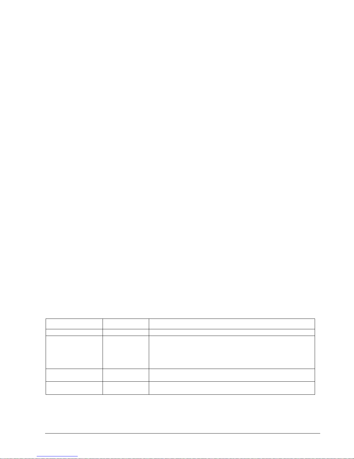
7 LED Indicator
The module has various display LEDs. The function of the LED display
Anzeige
Bezeichnung
Funktion
LED Green
PWR
power indicator
LED Green
DATA
LED flashes 3 times after power on
Flashing at 1-Wire activity
Transmitting data via the data interface
Flashes rapidly if "KAL Receive" has been activated no
“KAL messages" receive.
LED Green
Data interface
Network Link LED
LED Yellow
Data interface
Network activity LED

Art No 11319
All rights reserved. Reprinting,, also in excerpts, without prior permission of ESERA and E-Service GmbH prohibited. Technical changes
reserved. ESERA E-Service GmbH 2016
www.esera-automation.de 11319 Manual 1-Wire Controller 1 ETH V2.2 Page 3 von 4
8 Connetion
Modul topside (1-Wire Bus)
7 = GND
8 = 1-Wire Data
9 = + 5V Output
Modul buttom side (supply voltage)
1 = Minus supply voltage
2 = Plus supply voltage
9 Operating conditions
The operation of the assembly group can take place only on condition of observing the required voltage and the
ambient conditions. The operating position of the device is irrelevant. The device is meant to be used in dry or
humid areas.
Should condensed water build up within the sensor, an acclimatisation period of at least 2 hours must pass.
Assembly groups and components do not belong into the hands of children!
The building group can be operated only under the supervision of an electrically skilled person.
In industrial facilities, the accident prevention regulations of the federation of industrial professional associations for
electrical installations and equipments must be observed.
Do not operate the assembly group in an environment with inflammable gases, vapours or dusts or in an
environment where such gases, vapours or dusts may be found.
10 Assembly
The mounting place must be protected against moisture. The module may only be used in dry indoor rooms or in
protected outside areas. The device is designed for fixed installation within a switching cabinet.
11 Disposal Note
Do not dispose of this device in the household waste. Electronic devices must be disposed of in
accordance with directives for disposing of waste electrical and electronic equipment at local
collection points for electronic waste material.
12 Safety Instructions
When using products that come into contact with electrical voltage, the valid VDE regulations must be observed,
especially VDE 0100, VDE 0550/0551, VDE 0700, VDE 0711 and VDE 0860
All final or wiring work must be carried out with the power turned off.
Before opening the device, always unplug or make sure that the unit is disconnected from the mains.
Components, modules or devices may only be put into service if they are mounted in a contact proof housing. During
installation they must not have power applied.
Tools may only be used on devices, components or assemblies when it is certain that the devices are disconnected
from the power supply and electrical charges stored in the components inside the device have been discharged.
Live cables or wires to which the device or an assembly is connected, must always be tested for insulation faults or
breaks.
If an error is detected in the supply line, the device must be immediately taken out of operation until the faulty cable
has been replaced.
When using components or modules it is absolutely necessary to comply with the requirements set out in the
accompanying description specifications for electrical quantities.

All rights reserved. Reprinting,, also in excerpts, without prior permission of ESERA and E-Service GmbH prohibited. Technical changes
reserved. ESERA E-Service GmbH 2016
www.esera-automation.de 11319 Manual 1-Wire Controller 1 ETH V2.2 Page 4 von 4
If the available description is not clear to the non-commercial end-user what the applicable electrical characteristics
for a part or assembly are, how to connect an external circuit, which external components or additional devices can
be connected or which values these external components may have, a qualified electrician must be consulted.
It must be examined generally before the commissioning of a device, whether this device or module is basically
suitable for the application in which it is to be used.
In case of doubt, consultation with experts or the manufacturer of the components used is absolutely necessary.
For operational and connection errors outside of our control, we assume no liability of any kind for any resulting
damage.
Kits should be returned without their housing when not functional with an exact error description and the
accompanying instructions. Without an error description it is not possible to repair. For time-consuming assembly or
disassembly of cases charges will be invoiced.
During installation and handling of components which later have mains potential on their parts, the relevant VDE
regulations must be observed.
Devices that are to be operated at a voltage greater than 35 VDC / 12mA, may only be connected by a qualified
electrician and put into operation.
Commissioning may only be realized if the circuit is built into a contact proof housing.
If measurements with an open housing are unavoidable, for safety reasons an isolating transformer must be installed
upstream or a suitable power supply can be used.
After installing the required tests according to DGUV Vorschrift 3 must be performed.
13 Warranty
ESERA guarantees that the goods sold at the time of transfer of risk to be free from material and workmanship defects and
have the contractually assured characteristics. The statutory warranty period of two years begins from date of invoice. The
warranty does not extend to the normal operational wear and normal wear and tear. Customer claims for damages, for
example, for non-performance, fault in contracting, breach of contractual obligations, consequential damages, damages for
tort and other legal grounds are excluded. Excepting to this, ESERA accepts liability for the absence of a guaranteed quality
resulting from intent or gross negligence. Claims made under the Product Liability Act are not affected. If defects occur for
which the ESERA is responsible, and in the case of replacement goods, the replacement is faulty, the buyer has the right to
have the original purchase price refunded or a reduction of the purchase price. ESERA accepts liability neither for the constant
and uninterrupted availability of the ESERA for technical or electronic errors in the online offer.
We develop our products further and we reserve the right to make changes and improvements to any of the products
described in this documentation without prior notice. If you need documentation or information about older product versions,
contact us by email at info@eser-automation.de
14 Trademarks
All mentioned designations, logos, names and trademarks (including those which are not explicitly marked) are trademarks,
registered trademarks or other copyright or trademarks or titles or legally protected designations of their respective owners
and are hereby recognized as such by us. The mention of these designations, logos, names and trademarks is made for
identification purposes only and does not represent a claim any kind on the part of ESERA, E-Service GmbH on these
designations, logos, names and trademarks. Moreover, from their appearance on these WWW pages it cannot be concluded
that designations, logos, names and trademarks are free of commercial property rights.
1-Wire is a product name of the company. Maxim Integrated Products, Inc., USA. further
information http://www.maxim-ic.com
15 Contakt
ESERA-Automation
E-Service GmbH
Adelindastrasse 20
87600 Kaufbeuren
Tel.: +49 8341 999 80-0
Fax: +49 8341 999 80-10
http://www.esera-automation.de/
support@esera-automation.de
WEEE-Nummer: DE30249510
 Loading...