

esera automation 11112 User Manual
Art. No. 11112
User Guide
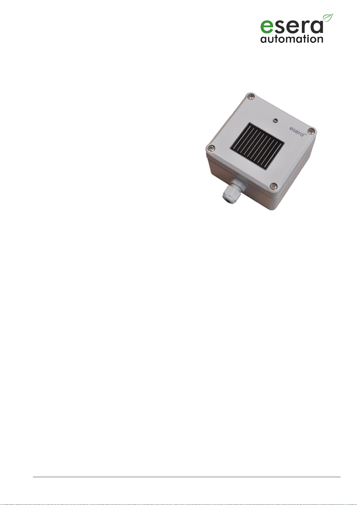
Solar Multisensor V4
for 1-Wire bus system
Single beam sensor based on a photovoltaic cell
Separate brightness sensor
Detection of ambient brightness,
day / night detection
Integrated temperature sensor for temperature
measurement for "perceived temperature” or
outside temperature
Waterproof sensor housing (IP54)
Connection via Push In terminal for cable
up to 1,5qmm cross-section
Easy to assemble
1 Introduction
Before you start mounting the 1-Wire Solar Multisensor and putting the device into operation, please read these
mounting and operating instructions carefully until the end, especially the section on safety instructions.
2 Product description
The 1-Wire Solar Multisensor is a combination sensor for solar-radiation, brightness and perceived temperature
that combines the advantages of semiconductor and photovoltaic sensors in one device.
The brightness sensor measures brightness values in the range of 10 - approx. 7000 lux, the PV sensor covers the
range up to approx. 1200W/m² and the temperature sensor outputs the felt temperature in the sun.
Since the solar sensor is a power sensor, the output is in watts per square meter (W/m²). The solar and brightness
sensors with their supplementary properties cover the entire range of applications for recording solar-radiation and
day/night detection and are therefore ideally suited for central light-, shutter- and shade control.
The 1-Wire Solar Multisensor is designed for permanent outdoor operation. The entire sensor is designed for a
temperature range of -40 to +85°C.
To ensure maximum reliability, the 1-Wire Solar Multisensor has an integrated monitoring of the supply voltage.
The sturdy plastic housing is designed for IP54 operating conditions. The cable entry is made by screw strangling
nipples. For wall mounting, a special mounting bracket is available for purchase as an accessory at our shop.
2.1 Photovoltaic sensor (solar sensor)
The photovoltaic sensor is designed to measure the solar-radiation in W/m². This makes the solar Multisensor very
suitable for controlling shading- or awning systems. The solar sensor covers an enormously large dynamic range
up to approx. 1200 W/m², which corresponds to approx. 1,000 up to 70,000 lux.
The sensor can be used well for estimating the expected performance of PV systems and finding a location.
Existing PV systems can be monitored by comparison measurements. Due to its design, the output voltage of the
sensor does not run with a linear characteristic curve and is subject to a certain temperature influence.
The measured solar-radiation power of the solar cell is output in watts per square meter (W/m²) by formula,
(evaluation script) and a variable for controlling a shading system is output.
The solar sensor is typically mounted on a mounting bracket (Art. No. 20003) at an inclination of approx. 45° with
orientation to the south. This allows a comparative measurement for PV systems. Rain and snow will also slide
faster from the top of the sensor.
All rights reserved. Reproduction as well as electronic duplication of this guide, complete or in part, requires the written consent of ESERAAutomation or E-Service GmbH. Errors and technical modification subject to change. ESERA-Automation, E-Service GmbH 2019
www.esera.de 11112 V1.0 R1.0 Manual Page 1 of 5

2.2 Brightness sensor
The brightness sensor is used for the measurement of low light values and for sunrise and sunset detection. For
example, blinds can be opened or closed in the morning and evening.
A special photodiode, with a human-like detection light spectrum, converts the ambient brightness to an analog
voltage value.
The evaluation script converts the output voltage value to the current brightness value in lux and outputs a variable
for day / night control, e.g. for roller shutter control.
2.3 Temperature sensor
The solar Multisensor contains a temperature sensor that measures the temperature felt in the sun. Depending on
the weather conditions, the temperature values can deviate greatly from those measured near the ground. By
mounting the temperature sensor inside the housing, short-term falsifications of measured values due to draughts
or gusts of wind are greatly reduced.
With the temperature sensor, comparative temperature values for mounted PV modules can be easily recorded and
used to calculate the possible power reduction and plausibility check.
Depending on the installation location, the sensor can also be used as an outdoor temperature sensor. For the
exact recording of the normal outdoor temperature we recommend our 1-Wire temperature sensor waterproof, Art.
No. 11111 or the 1-Wire Multisensor Temperature, Humidity and Brightness, Art. No. 11135.
3 Technical data
1-Wire chip/device 1 x DS2438 (Multisensor)
Solar sensor Measuring range up to approx. 1200 W/m2 (converted approx. 1,000 - 70,000 lux)
PV measuring cell is a high-quality monocrystalline glass PV cell
Detection range: +/-50° (for half sensitivity)
Functions DS2438: XSens, 0mV = darkness, resolution 10mV, 10 Bit
Brightness sensor Measuring range 10 - approx. 7000 Lux,
Peak sensitivity 570 nm, light sensitivity similar to the human eye
Detection range: +/-50° for half sensitivity
Functions DS2438: VAD, brightness value (5V = darkness), 0 - 5V, resolution 10mV, 10 Bit
Temperature sensor Measuring range -50°C to +125°C, resolution 0.03125°C, 13 Bit
Interface: 1-Wire Bus (5V, Data and Ground)
Operating voltage: 5 V= (+/-10%), resolution 10mV, 10 Bit
Current consumption: max. 2mA @ 5V (light sensor full scale)
Connection: Screwless pressure terminals for cables up to 1.5qmm cross-section
4 Ambient conditions
Protection type: IP54
Protection class: III
Temperature, Operation: -40°C to +85°C
Humidity: 10 - 92% (non-condensing)
Dimensions: 82 x 80 x 57mm (L x W x H) without cable gland
Housing color: Light grey
Housing material: ABS plastic (acrylonitrile-butadiene-styrene)
5 Conformity
EN 50090-2-2,
EN 61000-4-2 ESD,
EN 61000-4-3 HF,
EN 61000-4-4 Burst,
EN 61000-4-5 Surge,
EN 61000-6-1 Fault-free operation,
EN 61000-6-3 Stray radiation,
RoHS
6 Software
The solar multisensor is read by 1-Wire commands for DS2438 device and supported by many software programs
and devices, such as Loxone SPS, WAGO SPS (via OWOS), OWFS, FHEM (Linux), IP-Symcon or microcontroller
applications.
Assignment of DS2438 inputs: VDD = operating voltage (Volt), VAD = brightness (Volt), XSENS = irradiation (Volt).
Evaluation brightness sensor:
Brightness (Lux) = (VDD-VAD) * 700, example: (5V-1.25 V) * 700 = 2625 lux
Note: it should be noted that the sensor has a negative evaluation, which means approx. 5V equals darkness and
approx. 0V equals full lighting.
All rights reserved. Reproduction as well as electronic duplication of this guide, complete or in part, requires the written consent of ESERAAutomation or E-Service GmbH. Errors and technical modification subject to change. ESERA-Automation, E-Service GmbH 2019
www.esera.de 11112 V1.0 R1.0 Manual Page 2 of 5
 Loading...