

E-Senza SenzaBlock SB130 User manual
Manual
E-Senza Technologies GmbH | Bücklestr. 8
2b | 78467 Konstanz | Germany
SenzaBlock SB130
Tel.: +49 7531 36599- 10, Fax: +49 7531 36599-29 | info@e-senza.de | www.e-senza.de
Th
is is the safety alert symbol. It is used to alert you to potential personal injury
This symbol and the accompanying text alerts the reader to a situation which may
Doc
Version
V1.2.
Leveraging Power of Wireless
®
Safety Information
In order to ensure the safe use of the product described, you have to read and understand this
manual. The following notes provide information on how to use this manual.
User group of this manual
The use of products described in this manual is oriented exclusively to
– qualified electricians or persons instructed by them, who are familiar with applicable
standards and other regulations regarding electrical engineering and, in particular, the
relevant safety concepts.
– qualified application programmers and software engineers, who are familiar with the safety
concepts of automation technology and applicable standards.
E-Senza Technologies accepts no liability for erroneous handling or damage to products from ESenza Technologies or third-party products resulting from disregard of information contained in this
manual.
Explanation of symbols used and signal words
The following types of messages provide information about possible property damage and general
information concerning proper operation and ease-of-use.
hazards. Obey all safety messages that follow this symbol to avoid possible injury
or death.
The following types of messages provide information about possible property damage and general
information concerning proper operation and ease-of-use.
SenzaBlock is ESD sensitive!
• Prevent SenzaBlock OEM module or PCB inside the enclosure from touching your clothing.
Most clothing is insulative and retains a charge even when you are wearing a wrist strap.
• Wear a grounded wrist strap against your skin to eliminate static on your body
• Hold SenzaBlock by its enclosure or its edge. If you are removing a pluggable module, use
the correct tool.
cause damage or malfunction to the device, either hardware or software, or
surrounding property.
This symbol and the accompanying text provide additional information to the
reader. It is also used as a reference to other sources of information (manuals,
data sheets) on the subject matter, product, etc.
Leveraging Power of Wireless
®
Content
1 SenzaNET ..........................................................................................................1
1.1 Communication in SenzaNET ...........................................................................1
1.2 Network Elements ........................................................................................2
1.2.1 SenzaBlock .............................................................................................2
1.2.2 Gateway ................................................................................................2
1.2.3 SenzaWMS ..............................................................................................2
2 SenzaBlock SB130 ................................................................................................2
2.1 Features....................................................................................................2
2.2 Installation.................................................................................................3
2.2.1 Mechanical Installation...............................................................................3
2.2.2 Electrical Installation.................................................................................4
2.2.2.1 Power-supply Connection .....................................................................4
2.2.2.2 Device Connection .............................................................................4
2.2.2.3 Hardware Configuration – Analog Interfaces ..............................................6
2.2.2.4 Hardware Configuration – Digital IO Device Connection.................................7
2.2.2.5 SB130 Digital IO Combination Options .................................................... 10
2.2.2.6 Antenna Connection ......................................................................... 11
2.2.2.7 Software Configuration...................................................................... 12
2.3 Operation ................................................................................................ 13
2.3.1 LED Indicator Light.................................................................................. 13
2.3.2 Buttons................................................................................................ 13
3 Troubleshooting ................................................................................................ 14
4 Technical Support and Training ............................................................................. 15
5 Warranty ......................................................................................................... 16
6 Environmental Compliance ................................................................................... 16
7 CE conformity ................................................................................................... 17
Copying of this document in full or in part, and giving it to others and the use or communication
of the contents there of, are forbidden without express authority. Offenders are liable to the
payment of damages. All rights reserved for E-Senza Technologies GmbH, Konstanz, Germany in the
event of the grant of a patent or the registration of a utility model or design. (DIN 34-1-E)
Leveraging Power of Wireless®
1 SenzaNET
SenzaBlock is always operated as part of a wireless device network running the SenzaNET protocol.
This chapter gives a basic overview of SenzaNET, the devices involved, terminology and features.
Please refer to your SenzaWMS manual for more detailed information.
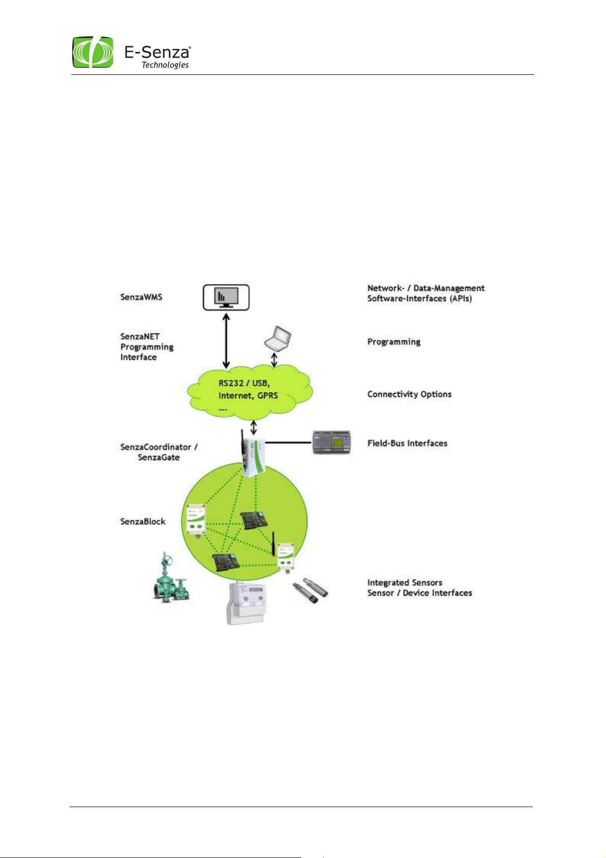
1.1 Communication in SenzaNET
The gateway (SenzaCoordinator/SenzaGate) is the network master, responsible for all
communication to/from the wireless network.
Hence, all communication to any network node is done through the gateway. This is possible either
via the SenzaWMS, the SenzaNET programming interface or through Field-Bus interfaces.
Fig. 1 SenzaNET System Overview
Manual SenzaBlock SB130 1 SenzaNET-Release: V4.0.1
Leveraging Power of Wireless
®
1.2 Network Elements
1.2.1 SenzaBlock
SenzaBlock represents the basic component of SenzaNET. SenzaBlock has mesh networking
capabilities and can interface with devices (e.g. sensors, actuators) at the same time.
SenzaBlocks are available from E-Senza Technologies in different variations for a multitude of
applications.
As adapter-devices or built-in modules, they enable all kinds of sensor and actuator devices to be
controlled wirelessly and exchange data through a self-organizing wireless mesh network with ultralow power consumption.
1.2.2 Gateway
SenzaNET supports integration of the Wireless Network with existing systems or products through
the gateway. You always need a network master to communicate to or from the SenzaBlock. It can
be a SenzaCoordinator or a SenzaGate. They not only support Network Layer functionality but also
provide interfacing to upper layers.
The gateways are available for a multitude of industrial interfaces: Ethernet, Serial, Modbus,
Profibus etc.
1.2.3 SenzaWMS
SenzaWMS is the software-suite accompanying SenzaNET. It provides a very friendly user-interface
for a comfortable administration of the wireless network and monitoring of each individual node.
With SenzaWMS, multiple networks can be managed in parallel, networked devices can be reconfigured, alarm messaging and data acquisition are automated. Comprehensive software-APIs and
data-export options allow seamless integration into existing IT-infrastructures.
2 SenzaBlock SB130
SenzaBlocks of the SB1x0 product family are integrated measurement transducers and wireless data
transmitters. They provide interfaces to standard sensors and field devices allowing them to
communicate wirelessly using SenzaNET.
2.1 Features
SenzaBlock SB130 supports up to four input and two output interfaces, both can be analog or digital,
with maximum 4 active interfaces at a time and with a specific input or output type multiple of 2. It
features an on-board internal temperature sensor DS75. “Input”-interface means an interface where
SenzaBlock collects signals, to process them and transmit wirelessly, whereas “output”-Interface
refers to an interface where SenzaBlock converts a wireless signal received into a control signal for
external devices.
The input-interfaces of SenzaBlock SB130 can be configured to collect the following types of signals:
• 0-20 mA or 4-20 mA current loops
• 0-2V or 0-10V
• Digital Input: detects rising edge (contact “closed”) and falling edge (contact “open”).
• Pulse: rising edges will be detected and accumulated as pulses
• S0: closing of S0-switch will be detected and accumulated
The output-interfaces of SenzaBlock SB130 can be configured for following types of output-signals:
• 0-20 mA or 4-20 mA current loops
• 0-2V, 0-10V
• Digital Output: generates rising edge (contact “closed”) and falling edge (contact “open”).
For detailed specifications of SB130, please refer to it’s datasheet available at
http://www.e-senza.de/products/senzablock.html
Manual SenzaBlock SB130 2 SenzaNET-Release: V4.0.1
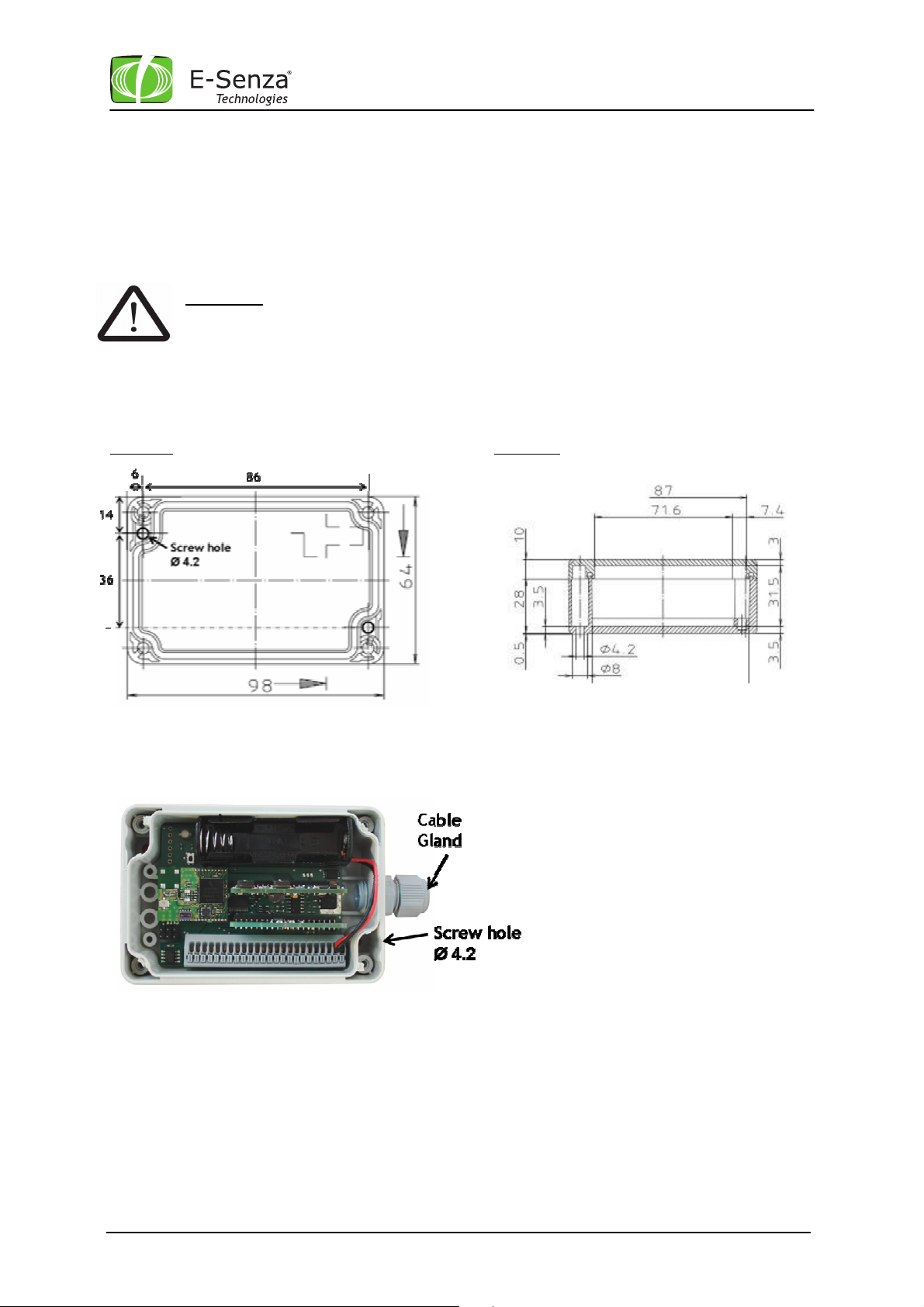
All dimensions in mm.
Leveraging Power of Wireless
®
2.2 Installation
2.2.1 Mechanical Installation
SenzaBlock’s standard enclosure can be wall-mounted using two screws of 4 mm diameter. See
photo and drawings below to locate the screw holes. After mounting SenzaBlock and completion of
electrical installation, make sure the cable gland is properly closed and the front cover is fixed
firmly using its four screws.
Important: Check cable gland, front screws and proper sealing of enclosure to ensure
adequate closure, as this is IP65 protected!
If no cable is used out of the SenzaBlock, the cable gland will not close properly.
Therefore a blanking plug MUST be fitted into the Cable Gland to obtain IP65 ingress
Protection !
Top view
Side view
Manual SenzaBlock SB130 3 SenzaNET-Release: V4.0.1
 Loading...