

Manual
E-Senza Technologies GmbH | Bücklestr. 82b | 78467 Konstanz | Germany
SenzaBlock SB110-T
Tel.: +49 7531 36599- 10, Fax: +49 7531 36599-29 | info@e-senza.de | www.e-senza.de
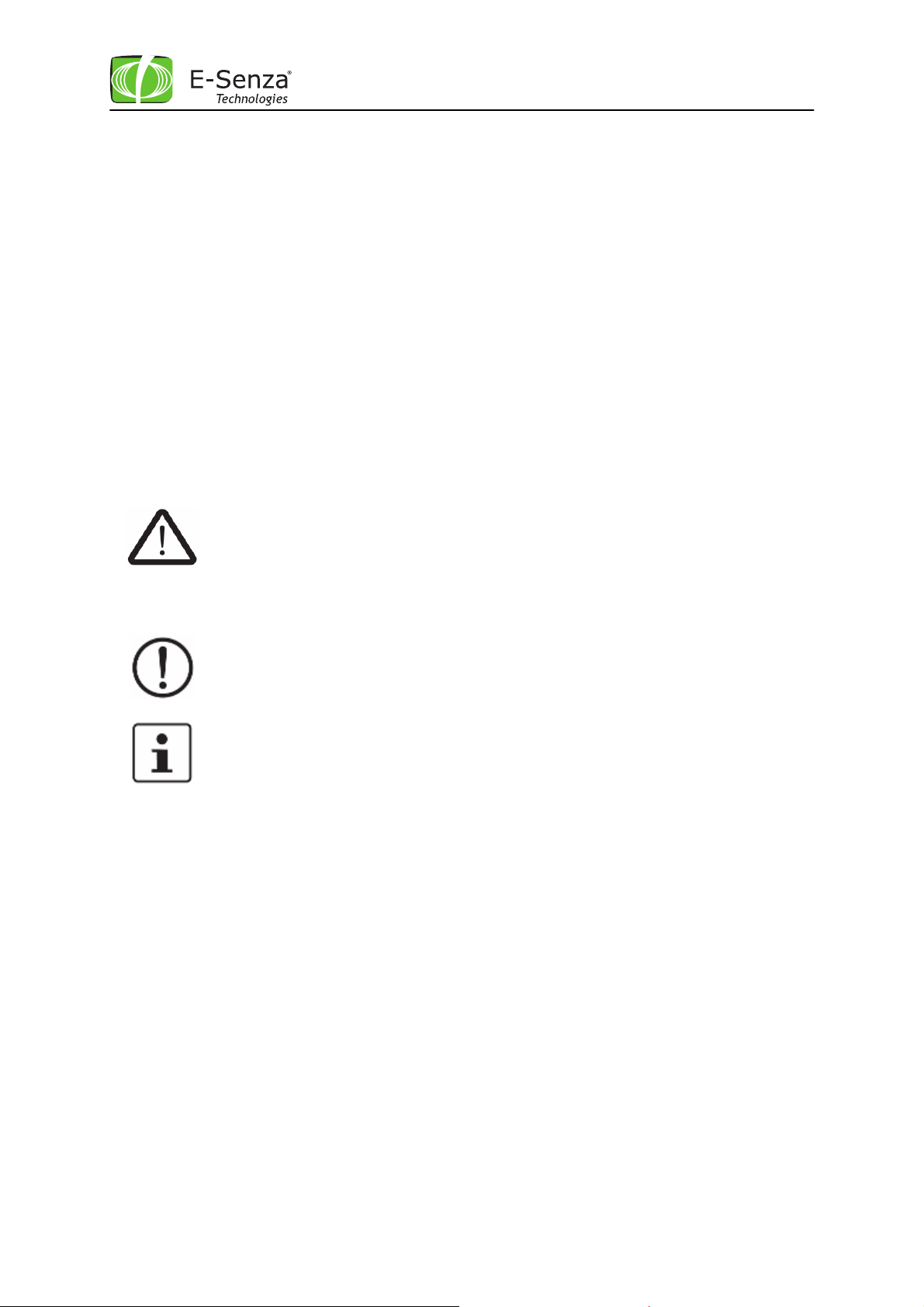
This is the safety alert symbol. It is used to alert you to pote
ntial personal injury
This symbol and the accompanying text ale
rts the reader to a situation which may
Doc V1.1.
Leveraging Power of Wireless
®
Safety Information
In order to ensure the safe use of the product described, you have to read and understand this
manual. The following notes provide information on how to use this manual.
User group of this manual
The use of products described in this manual is oriented exclusively to
– qualified electricians or persons instructed by them, who are familiar with applicable
standards and other regulations regarding electrical engineering and, in particular, the
relevant safety concepts.
– qualified application programmers and software engineers, who are familiar with the safety
concepts of automation technology and applicable standards.
E-Senza Technologies accepts no liability for erroneous handling or damage to products from ESenza Technologies or third-party products resulting from disregard of information contained in this
manual.
Explanation of symbols used and signal words
The following types of messages provide information about possible property damage and general
information concerning proper operation and ease-of-use.
hazards. Obey all safety messages that follow this symbol to avoid possible injury
or death.
The following types of messages provide information about possible property damage and general
information concerning proper operation and ease-of-use.
Battery Handling Guidelines
• Insert the battery correctly (+/-).
• Do not recharge
• Do not open or dispose in fire
• Do not heat above 100°C
• Do not expose contents to water
• Do not mix with used batteries or other battery types
Not considering the above steps may lead to explosion, leaking of battery and can cause damage!
SenzaBlock is ESD sensitive!
• Prevent SenzaBlock OEM module or PCB inside the enclosure from touching your clothing.
Most clothing is insulative and retains a charge even when you are wearing a wrist strap.
• Wear a grounded wrist strap against your skin to eliminate static on your body
• Hold SenzaBlock by its enclosure or its edge. If you are removing a pluggable module, use
the correct tool.
cause damage or malfunction to the device, either hardware or software, or
surrounding property.
This symbol and the accompanying text provide additional information to the
reader. It is also used as a reference to other sources of information (manuals,
data sheets) on the subject matter, product, etc.
Leveraging Power of Wireless
®
Content
1 SenzaNET ..........................................................................................................1
1.1 Communication in SenzaNET ...........................................................................1
1.2 Network Elements ........................................................................................2
1.2.1 SenzaBlock .............................................................................................2
1.2.2 Gateway ................................................................................................2
1.2.3 SenzaWMS ..............................................................................................2
2 SenzaBlock SB110-T..............................................................................................2
2.1 Features....................................................................................................2
2.2 Installation.................................................................................................2
2.2.1 Mechanical Installation...............................................................................2
2.2.2 Electrical Installation.................................................................................3
2.2.2.1 Connecting Sensor and Power-supply..............................................................3
2.2.2.2 SB110-T Input Combination Options ...............................................................5
2.2.2.3 Antenna Connection ..................................................................................5
2.2.2.4 Software Configuration ..............................................................................7
2.3 Operation ..................................................................................................7
2.3.1 LED Indicator Light....................................................................................7
2.3.2 Buttons..................................................................................................8
3 Troubleshooting ..................................................................................................9
4 Technical Support and Training ............................................................................. 10
5 Warranty ......................................................................................................... 11
6 Environmental Compliance ................................................................................... 11
7 CE conformity ................................................................................................... 12
Copying of this document in full or in part, and giving it to others and the use or communication
of the contents there of, are forbidden without express authority. Offenders are liable to the
payment of damages. All rights reserved for E-Senza Technologies GmbH, Konstanz, Germany in the
event of the grant of a patent or the registration of a utility model or design. (DIN 34-1-E)
Leveraging Power of Wireless®
1 SenzaNET
SenzaBlock is always operated as part of a wireless device network running the SenzaNET protocol.
This chapter gives a basic overview of SenzaNET, the devices involved, terminology and features.
Please refer to your SenzaWMS manual for more detailed information.
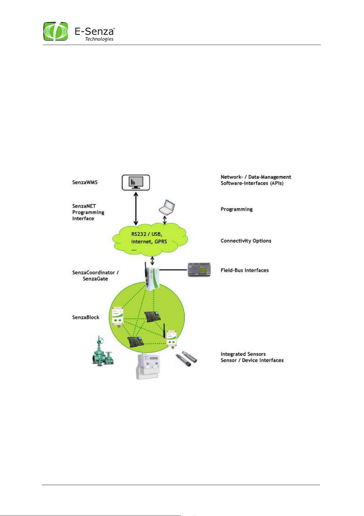
1.1 Communication in SenzaNET
The gateway (SenzaCoordinator/SenzaGate) is the network master, responsible for all
communication to/from the wireless network.
Hence, all communication to any network node is done through the gateway. This is possible either
via the SenzaWMS, the SenzaNET programming interface or through Field-Bus interfaces.
Fig. 1 SenzaNET System Overview
Manual SenzaBlock SB110-T 1 SenzaNET-Release: V4.0.1

Leveraging Power of Wireless
®
1.2 Network Elements
1.2.1 SenzaBlock
SenzaBlock represents the basic component of SenzaNET. SenzaBlock has mesh networking
capabilities and can interface with devices (e.g. sensors, actuators) at the same time.
SenzaBlocks are available from E-Senza Technologies in different variations for a multitude of
applications.
As adapter-devices or built-in modules, they enable all kinds of sensor and actuator devices to be
controlled wirelessly and exchange data through a self-organizing wireless mesh network with ultralow power consumption.
1.2.2 Gateway
SenzaNET supports integration of the Wireless Network with existing systems or products through
the gateway. You always need a network master to communicate to or from the SenzaBlock. It can
be a SenzaCoordinator or a SenzaGate. They not only support Network Layer functionality but also
provide interfacing to upper layers.
The gateways are available for a multitude of industrial interfaces: Ethernet, Serial, Modbus,
Profibus etc.
1.2.3 SenzaWMS
SenzaWMS is the software-suite accompanying SenzaNET. It provides a very friendly user-interface
for a comfortable administration of the wireless network and monitoring of each individual node.
With SenzaWMS, multiple networks can be managed in parallel, networked devices can be reconfigured, alarm messaging and data acquisition are automated. Comprehensive software-APIs and
data-export options allow seamless integration into existing IT-infrastructures.
2 SenzaBlock SB110-T
SenzaBlocks of the SB1x0 product family are integrated measurement transducers and wireless data
transmitters. They provide interfaces to standard sensors and field devices allowing them to
communicate wirelessly using SenzaNET.
2.1 Features
SenzaBlock SB110-T is designed for Temperature measurement. It features an on-board internal
temperature sensor and an interface for connecting an external 2-wire PT100 sensor. PT100 sensors
are standardized resistors, whose resistor-value changes with temperature. SenzaBlock SB110-T
measures this resistor value and directly converts it into temperature applying the conversion table
defined under DIN EN 60751.
For detailed specifications of SB110-T, please refer to it’s datasheet available at:
http://www.e-senza.de/products/senzablock.html
2.2 Installation
2.2.1 Mechanical Installation
SenzaBlock’s standard enclosure can be wall-mounted using two screws of 4 mm diameter. See
photo and drawings below to locate the screw holes. After mounting SenzaBlock and completion of
electrical installation, make sure the cable gland is properly closed and the front cover is fixed
firmly using its four screws.
Manual SenzaBlock SB110-T 2 SenzaNET-Release: V4.0.1

All dimensions in mm.
Important: Check cable gland, front screws and proper sealing of enclosure to
ensure adequate closure, as this is IP65 protected !
If no cable is used out of the SenzaBlock, the cable gland will not close properly.
Therefore a blanking plug MUST be fitted into the Cable Gland to obtain
IP65 ingress protection !
Top view
Side view
Leveraging Power of Wireless
®
2.2.2 Electrical Installation
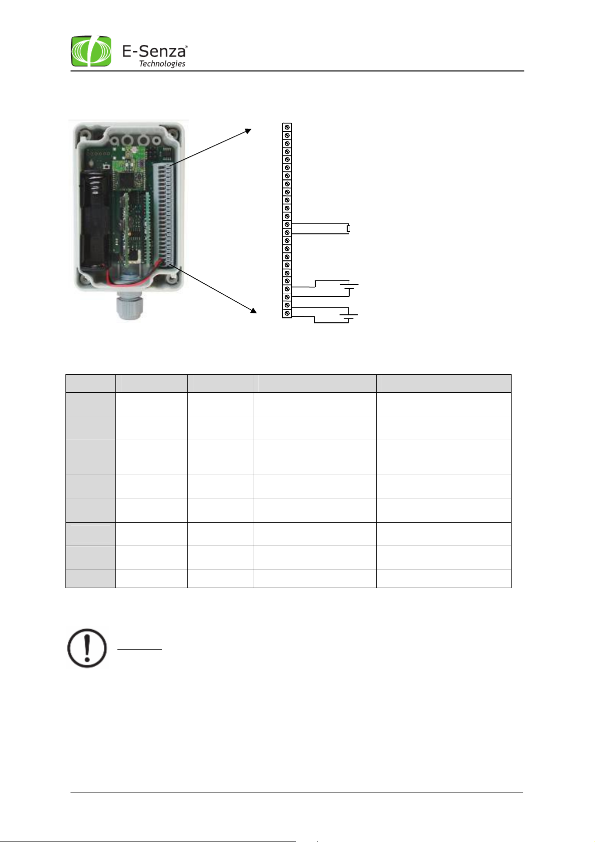
2.2.2.1 Connecting Sensor and Power-supply
SB110-T can be powered either with 2 x 1,5V “AA”-type batteries or with an external power supply,
with a supply-voltage ranging from 12V to 24V. Both power-supply options are connected
differently, please refer to the table below to identify correct connector pins.
The PT100-sensor is connected to SenzaBlocks pins as in table below.
Both external power supply and PT100 connection cables have to be lead through the enclosures
cable glands before being connected.
Manual SenzaBlock SB110-T 3 SenzaNET-Release: V4.0.1
Important: An external power supply must not be connected to Pins
reserved for battery-power. Doing so will damage SB110-T !
Pin 24
Pin 23
Pin 1
+
-
GND
GND
-
PT100
GND
Pin 13
Pin 14
Pin 21
Pin 22
+
Leveraging Power of Wireless
V
external
V
external
V
V
Batt
Batt
Pin No Pin Name Pin Type Description Comments
®
1 to 12 N/A N/A Not used
13 PT_IN Input PT100 Input
14 PT_IN Input PT100 Input
15 to20 N/A - Not used
21 DC_IN Power Input
22 GND GND
23 Batt_In
24 GND GND
Table 1 Connector Details
Battery
Input
External Power Supply
Positive (+12 V / +24V)
External Power Supply
Ground
Battery Supply Positive
(+3V).
Battery Ground
Important: When Switching from Battery Power to External Power Supply,
don’t forget to short the pins of connector R13 (see picture below). This is achieved with
help of a jumper. The pins must be open when battery powered!
Do Not Connect any wire to
these Pins
Connect 1 wire of the
PT100 Sensor here
Connect second wire of
PT100 here
Pin is connected to GND
Do Not Connect any wire to
these Pins
Be careful about polarity
when connecting !
Battery Voltage must not
exceed 3V
Manual SenzaBlock SB110-T 4 SenzaNET-Release: V4.0.1

An Antenna cable is connected to the
R13
Interface
Board
S2
Foil Connector
S1
Radio
Board
Leveraging Power of Wireless
®
Fig. 2 SenzaBlock Board-Layout
2.2.2.2 SB110-T Input Combination Options
Following configurations option can be chosen for SB110-T, where DS75 is the internal temperature
sensor and PT100 the PT100-interface.
SB110-T Channel1
DS75
PT100
Disabled
2.2.2.3 Antenna Connection
2.2.2.3.1 SB110-T OEM-module (order-code SB110-T-O)
Manual SenzaBlock SB110-T 5 SenzaNET-Release: V4.0.1
onboard U.FL connector located on
radio board. Avoid mechanical stress
to the cable connection, since RFperformance will be affected in case
connector is not fixed properly.

Please note that whenever you open and
Leveraging Power of Wireless
®
2.2.2.3.2 SB110-T with IP54-enclosure (order-code SB110-T-E54)
SenzaBlock’s IP54-enclosure comes with a reverse-SMA
antenna connector (“male”) and an applicable IP54
Antenna. Just plug antenna onto connector and turn it in
clockwise direction until it is fixed tightly. Loose fixing
of the Antenna might affect RF-performance of
SenzaBlock.
2.2.2.3.3 SB110-T with IP65-enclosure (order-code SB110-T-E65)
Additionally to the installation of an IP54-Antenna, SenzaBlock’s IP65-enclosure requires to add a
sealing-washer and a sealing-rubber before putting antenna onto connector. Refer to pictures below
to follow the sequence of installing these parts.
2.2.2.3.4 SB110-T with internal antenna (order-code SB110-T-I)
Manual SenzaBlock SB110-T 6 SenzaNET-Release: V4.0.1
close the enclosure, do not forget to check
the antenna cable which is connected to the
onboard U.FL connector located on radio
board and to the internal antenna inside the
cover of the enclosure.

Leveraging Power of Wireless
®
For best RF performance SenzaBlock has to be kept or mounted at the highest possible
place (2m height is ideal) with the external antenna pointing to ceiling or sky.
When using the internal antenna, optimal performance is reached when axis of antenna
is oriented horizontally and the antennas surface is in upright position.
See following picture:
2.2.2.4 Software Configuration
Hardware and Software Configuration of SenzaBlock must be consistent for SenzaBlock to function
properly and to make sure that data collected is interpreted correctly by SenzaNET as well as for
output signals to be generated correctly.
SenzaBlock’s must be authenticated in SenzaNET and software-configured to the sensors / devices
connected to it before data is transmitted.
Such configuration is done through the networks’ gateway. You can either use the SenzaWMS
software-suite to do this or send AT-commands to the gateway.
Please refer to the SenzaWMS Manual and/or the SenzaNET Programming Manual.
2.3 Operation
SenzaBlock will mostly be controlled remotely through SenzaNET. To simplify setup and change
procedures, SenzaBlock’s enclosure are equipped with an LED indicator light and two buttons. They
allow to monitor and control some basic functions of SenzaBlock.
2.3.1 LED Indicator Light
The LED-indicator light gives you a quick indication of the SenzaBlocks operational status:
Normal operation: LED shows red when SenzaBlock reads sensor data and/or outputs data
through one of it’s device interfaces.
LED then turns green when data is sent wirelessly.
Network problem: LED blinks red whenever SenzaBlock has lost connection and is scanning for
a neighboring node to re-establish network connection.
Manual SenzaBlock SB110-T 7 SenzaNET-Release: V4.0.1

2.3.2 Buttons
Leveraging Power of Wireless
®
Power Button
This button is used to switch SenzaBlock ON or OFF. Press this button
shortly and release it, power status of the SenzaBlock will change.
In case of SenzaBlock OEM module without cover and key panel connected
to it, use the onboard button S2 (see Fig. 2 above).
When power was removed from SenzaBlock, the Power button
must be pressed to switch SenzaBlock ON after re-connecting
power.
In case of SenzaBlock OEM module without cover and key panel
connected to it, use the onboard button S2 (see picture above)
to switch ON / OFF.
When SenzaBlock is restarted, the configuration parameters set over
ATCommands or over SenzaWMS will be stored and will be active at Start
Up.
F1 Diagnostics Button
The following tests can be performed using the diagnostics button:
• Battery Status Test
• Radio Signal Strength
• Network Connection Test
The test sequence will be aborted, if there is no new action on the Test
button for 1 minute. At every pressing of this button, the LED shows red
color.
Start Test Procedure:
• Press button and hold it
• After 2 seconds, the LED will toggle between green and red to
indicate Test Mode was started
1. Battery Test
• Press button once again to enter battery test
• LED will indicate Battery status:
o LED green: Battery is full
o LED red: Battery is turning empty
In case of power supply, LED will be always green.
2. Radio Signal Strength
• Press button again to enter Radio Signal Strength Test
• SenzaBlock reads last stored Radio Signal Strength data (from last
message received)
o LED green: Signal Strength good
o LED orange: Signal Strength medium
o LED red: Signal Strength bad
3. Network Connection Test
• Press button again to enter Network Connection Test
• SenzaBlock reads number of data packets waiting for transmission
o LED green: network connection stable
Manual SenzaBlock SB110-T 8 SenzaNET-Release: V4.0.1

R13 Connected /
Internal Reset
Switch S1
o LED red: communication with parent very weak.
End Test
• Press button again to leave test mode
• LED blinks orange for 1 second
• Reentering Test Mode is possible only after that time
Throughout the test procedure, SenzaBlock’s normal network functionality
will not be stopped.
Press S1 (refer to Fig. 2) to set the SenzaBlock to default factory settings.
Please pay attention, pressing this switch will remove all the
configuration data from the block and set it to the default
conditions as received from the factory.
The default factory settings can be found in the SenzaWMS
manual or in the AT Commands Manual.
Leveraging Power of Wireless
®
3 Troubleshooting
Problem Possible Reason
SenzaBlock not
powered
External Voltage
No Connection to
In case of
Battery level
dropping very
fast
SenzaBlock not in
Low Battery Check Battery Voltage Nominal battery voltage
too low
SenzaBlock or
Reverse Polarity
or Connections at
the Wrong Pins
External power
R13 Not Shorted
shorted
Network
Possible cause Remarks
is 3V, minimal battery
voltage is 2,4V. In case of
empty battery use
Energizer L91 1.5V AA
Batteries for best
performance.
Check the Voltage Level External voltage must be
between 12V to 24V.
Check connection as per
Table 1
Short R13, see Fig. 2
Remove R13
Check network connection SenzaBlock will consume
Connecting the power
supply at the wrong Pins
can damage the
SenzaBlock!!
battery faster, if it has to
scan for the Network.
See Below to section
SenzaBlock not
connecting to
Coordinator
Manual SenzaBlock SB110-T 9 SenzaNET-Release: V4.0.1
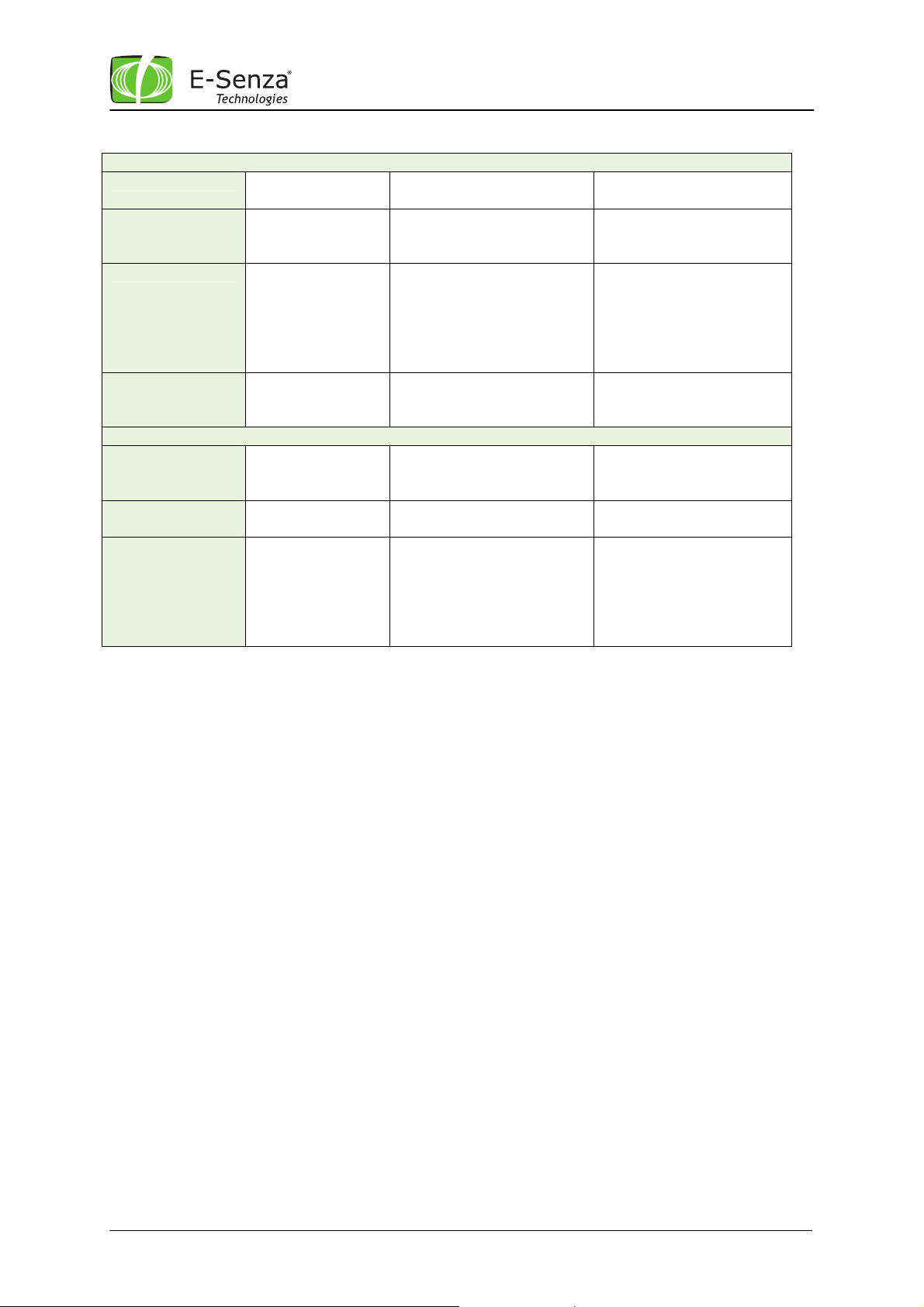
No Sensor Value No Sensor
Connected
Wrong DIP Switch
Setting
Wrong software-
configuration
Interface Board
Not Connected
Properly
SenzaBlock not
connecting to
Coordinator
No power or low
SenzaBlock is
Antenna
Connection not
proper
Battery Voltage
denied to access
the network.
Check the Sensor
Connection as per Table 1
Set the DIP switch as per
the setting shown in Fig.3
Select the right Sensor
Type for the SenzaBlock
from the Edit Window in
the Status Tab of
SenzaWMS or re-send ATCommand (AT+1)
Check the Connection and
Direction for the Interface
Board
Check antenna connection
Check voltage level
The user has denied the
access of that specific
block into one specific
network (for one gateway)
via SenzaWMS or with AT
Commands.
4 Technical Support and Training
Leveraging Power of Wireless
By pressing the Internal
Reset Switch S1 the
denial list will be
cleared. Block should be
now able to connect to
your network.
®
Send your technical questions directly to our team of product specialists.
Email: support@e-senza.de
Phone: +49 7531 365 99 – 19 9am – 5pm Central European Time
Trainings are available on a regular basis and can be arranged on request as well.
Visit our website for the latest training schedule:
http://www.e-senza.de/en/sales/training.html
or get in touch with our team in case of questions or specific training needs:
training@e-senza.de
Manual SenzaBlock SB110-T 10 SenzaNET-Release: V4.0.1
Leveraging Power of Wireless
®
5 Warranty
E-Senza Technologies warrants that its product will at the time of shipment be free and clear of all
liens and encumbrances and will be free from defects in material and workmanship and will
conform to specifications. If products sold are not as warranted, E-Senza shall, at its option, refund
the purchase price, repair or replace the product, provided proof of purchase and written notice of
nonconformance is received within one year from date of initial shipment, and provided said
nonconforming products are, with E-Senza’s written authorization, returned FOB E-Senza’s plant or
authorized repair center within 30 days from expiration of said 1-year period. Upon verification that
the product does not conform to this warranty, E-Senza will pay the cost of transporting such
replacement or repaired goods to Buyers plant within Germany. This warranty shall not apply to any
products E-Senza determines have been, by Buyer or otherwise, subjected to testing for other than
specified electrical characteristics or to operating and/or environmental conditions in excess of the
maximum values established in applicable specifications, or have been subject to mishandling,
misuse, neglect, improper testing, repair, alteration, damage, assembly or processing that alters
physical or electrical properties. This warranty excludes all costs of shipping, customs clearance and
related charges outside Germany.
In no event will E-Senza be liable for any incidental or consequential damages. This warranty
extends to Buyer only and not to buyers customers or users of buyers products and is in lieu of all
other warranties whether express, implied or statutory including implied warranties of
merchantability or fitness.
6 Environmental Compliance
All products from E-Senza are RoHS compliant.
Dispose off SenzaBlock and batteries in accordance with WEEE regulations of your country.
Manual SenzaBlock SB110-T 11 SenzaNET-Release: V4.0.1

7 CE conformity
SenzaBlock SB110-T is authorized for use in Europe.
Leveraging Power of Wireless
®
Manual SenzaBlock SB110-T 12 SenzaNET-Release: V4.0.1

Leveraging Power of Wireless
®
Manual SenzaBlock SB110-T 13 SenzaNET-Release: V4.0.1
 Loading...