

Page 1

Portable Ionization Test Kit
Operation and Maintenance
PS-2062 6/05 Page 1 of 4
Tech Brief
Made in America
© 2005 DESCO INDUSTRIES INC.
Employee Owned
Description
Our Portable Ionization Test Kit is a
portable and cost effective means of
verifying the performance of a wide
variety of ionization equipment. The
Test Kit includes a 42721 Digital
Fieldmeter, an Isolated Plate
Assembly, and a Charger. The
Charger is used to place a 1000V
charge on the isolated adapter plate
assembly, making it possible to also
measure the neutralization
performance of air ionization
equipment.
NOTE: Our 42721 Digital
Fieldmeter is designed to operate
with our 42755 Portable Ionization
Test Kit. It is not compatible with
other brands.
Currently there are no established
standards describing a periodic
verification device or procedure for
air ionizers. The ESD Systems.com
Portable Ionization Test Kit has been
designed to make measurements that
correspond to those made by using a
charged plate analyzer and ESD
Association's Standard 3.1. While
the Ionization Test Kit provides
convenience and portability, it does
not meet all of the requirements of
the ESD Association Standard. ESD
Systems.com recommends our
model 42630 Charged Plate
Analyzer if precise measurements
are required.
The Portable Ionization Test Kit
includes a slide-on isolated plate
assembly, a ±1000 volt charging unit
and a durable thermoplastic carrying
case with custom cut-outs for all of
the above components along with
the model 42721 fieldmeter. The
42721 Digital Fieldmeter can be
purchased separately.
Inspection
Remove the kit from the carton and
inspect for damage. Each kit
includes:
1 Digital Fieldmeter (Item 42721)
1 Isolated Plate Assembly
1 ± 1000 Volt Charger
1 9 Volt alkaline battery (installed)
1 Carrying case
Taking Balance
Measurements
The Portable Ionization Test Kit has
been designed to match the compact
size and hand held convenience of
the 42721 Digital Fieldmeter. Use
the following procedure to verify the
balance of air ionization equipment.
This quick and easy procedure will
indicate if the piece of ionization
equipment is working within the
manufacturer's specifications or user
requirements. It is extremely
important that ionizers be checked
regularly for balance. An ionizer
operating in an out-of-balance state
can damage sensitive electronic
components or assemblies.
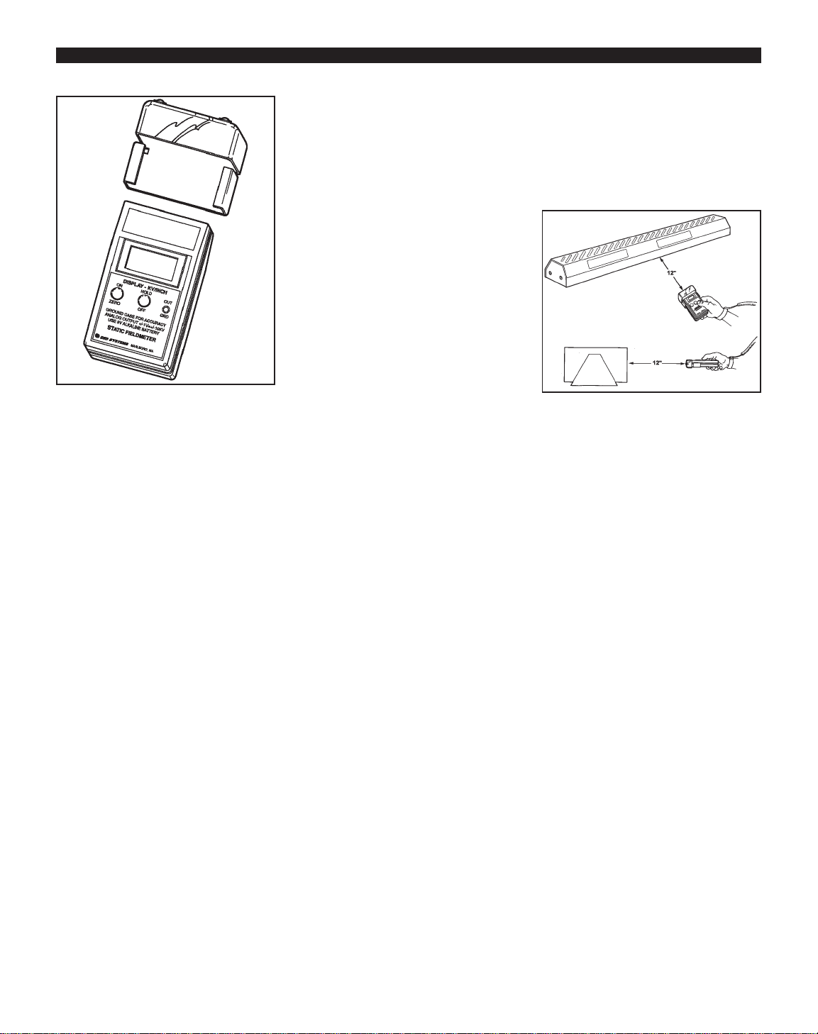
1. INSTALLING THE ISOLATED
PLA TE ASSEMBLY- The case of
the Model 42721 Fieldmeter has two
slots along its slides. The top slot is
closest to the front of the instrument.
Slide the tabs of the Isolated Plate
Assembly into the top slot of the
meter case as far as they go.
Figure 1. 42755 Portable Ionization Test Kit
Page 2
PS-2062 Page 2 of 4
© 2005 DESCO INDUSTRIES INC.
Employee Owned
2. ZERO THE INSTRUMENT -
Make connection between the
Adapter Plate Assembly and the
Digital Fieldmeter case either
through your finger or a test lead.
Face the Fieldmeter away from
charged objects and press the
ON/ZERO button. Hold until the
display reads zero. The instrument
may also be zeroed by pointing it
toward a known grounded surface
(such as the palm of the opposite
hand) and depressing the ON/ZERO
button. Although you must be
careful not to contact the recessed
sensor plate, the amount of spacing
between the instrument and the
target is not critical when zeroing the
instrument.
NOTE: The 42721 has a conductive
case that provides a ground
reference for the measuring circuit.
For accurate measurements it is
necessary that the person holding
the meter be properly grounded.
3. TAKE A MEASUREMENT -
Locate the meter in an ionized
environment at the appropriate
distance from the device under test
(typically 12"). The static field
displayed is the actual balance of the
ionizer or voltage offset. NOTE:
When testing pulsed ionizer systems,
the voltage displayed is constantly
changing. This pulse rate may be
faster than the display update rate of
the fieldmeter, therefore the
displayed voltage is an average of
the actual voltage. This average
reading is more accurate than
analog style meters which only
display positive or negative values.
AUTO SHUTDOWN TIMER
During normaloperation (not during
ZERO) a blinking decimal point
indicates the AUTO SHUTDOWN
TIMER is enabled. If the AUTO
SHUTDOWN TIMER is disabled
the decimal point will be on
continuously.
Holding down the ZERO button,
while unit is ON, for less than 3
seconds resets the AUTO
SHUTDOWN TIMER (if enabled).
The AUTO SHUTDOWN TIMER is
enabled or disabled by turning on the
unit and keeping the ON/ZERO
button pressed then toggling the
HOLD/OFF button. Enable/disable
of the AUTO SHUTDOWN TIMER
is indicated by the decimal point:
DP on
= timer on, DP off = timer off.
AUTO SHUTDOWN TIMER state
is maintained during power off.
AUTO SHUTDOWN TIMER can be
continually toggled as long as the
ON/ZERO button remains pressed,
up to 20 seconds, after which the
unit will turn off. A blinking decimal
point indicates the AUTO
SHUTDOWN TIMER is active.
During the last minute before power
off ALL annunicators will blink at a
fast rate. Pressing any button will
reset the timer. Timeout is nominally
15 minutes.
Taking Discharge Measurements
In order to verify that an ionizer is
operating properly it is also
important that its ability to neutralize
or discharge static electricity is
measured. The following procedure
will measure an ionizer's discharge
time.
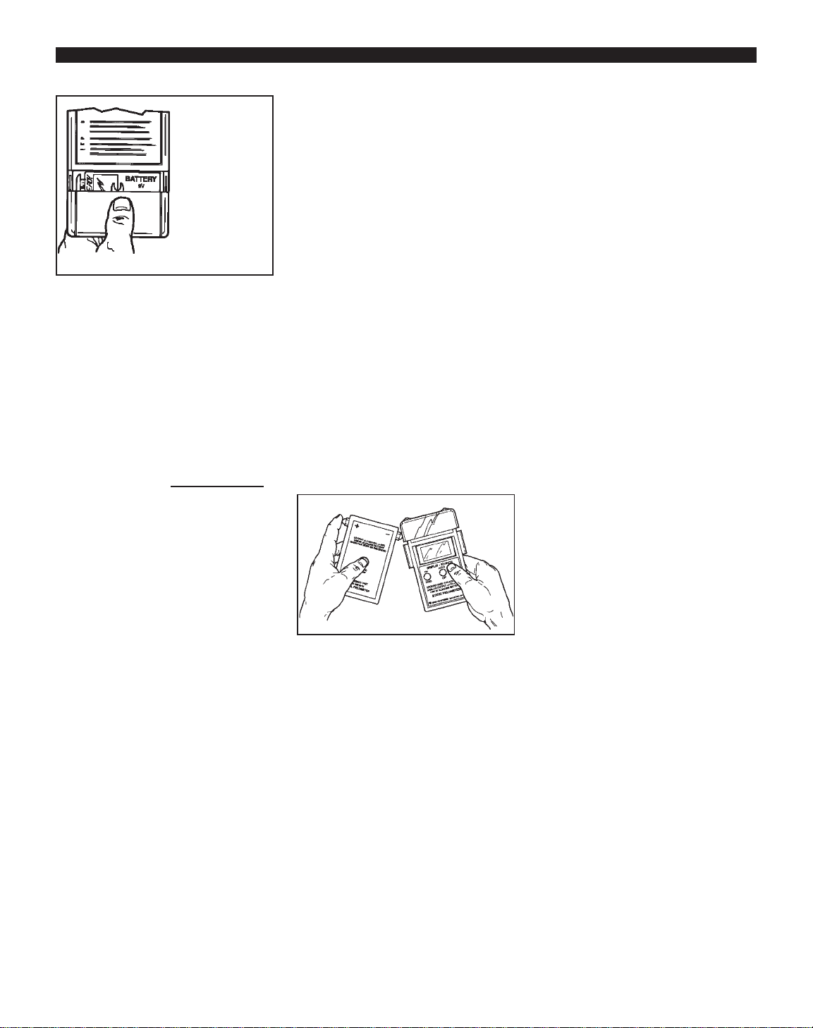
1. OPERATING THE
CHARGING UNIT - The Charger
has a momentary push-button that
turns on the power to the unit.
Holding the button down supplies
power to the output terminals.
2. OUTPUT CONTACTS - Two
output contacts are provided on the
Charger. They are connected to an
internal power source. When one
contact is connected to ground the
other contact will provide a charge
of the indicated polarity. The
Charger is designed so that an
operator can press the power button
and touch an output contact,
simultaneously with the fingers of
the same hand.
Figure 2. Installing the Isolated Plate
Assembly on the 42721 Digital
Fieldmeter
Figure 4. Taking a balance
measurement.
Page 3
PS-2062 Page 3 of 4
© 2005 DESCO INDUSTRIES INC.
Employee Owned
3. POLARITY SELECTION - The
terminals are labeled (+) and (-). To
provide a POSITIVE voltage output,
connect the negative (-) terminal to
ground. Press and hold the power
switch. To provide a NEGATIVE
voltage output, connect the positive
(+) terminal to ground. Press and
hold the power switch.
4. GROUNDING - IMPORT
ANT!
For the charging unit to work
correctly, the operator or the
fieldmeter must be properly
grounded. Aground path from an
output contact must exist.
5. IONIZER DISCHARGE TIME
MEASUREMENTS - Locate the
42721 and the Isolated Plate
Assembly in the appropriate location
for measurements.
6. POSITIVE DISCHARGE
MEASUREMENT - For positive
discharge measurement, touch the
negative (-) terminal of the Charger
while pressing the charging button
on the Charger. Momentarily touch
the positive terminal to the Isolated
Plate Assembly. The 42721 reads
approximately +1.10kV. By using a
stop watch or other timing device,
determine the time needed for the
voltages to decrease from +1.10kV
to + 0.01kV. This is the positive
discharge time.
7. NEGATIVE DISCHARGE
MEASUREMENTS - For negative
discharge measurements, touch the
(+) output terminal while pressing
the charging button on the Charger.
Momentarily touch the negative
terminal to the Isolated Plate
Assembly. Follow the instructions
for the positive discharge
measurement above.
IMPORTANT: A ground path must
be provided between one of the
output terminals of the charging unit
and the ground reference of the
Fieldmeter and Adapter Plate. This
is normally provided by holding the
Charger in one hand and the
Fieldmeter with Adapter Plate in the
other. If this is not possible, test
leads must be used to connect one to
the Charger output terminals and the
Fieldmeter ground connection.
Calibration
The overall accuracy of the 42755
Test Kit is ± 5% nominal.
Calibration of the Ionization Test Kit
should only be performed by the
factory. The 42755 is calibrated to
NIST traceable standards. Contact
our Customer Service Department
for details.
Maintenance
BATTERY CARE
1. 42721 Fieldmeter - Change
batteries at least once a year. The
unit should be off when replacing the
battery. Normal battery life is about
40 hours of use. Replace the battery
when the “BAT” indicator appears in
the display above the “HOLD”
indicator position for more than an
instant.
2. Charging Unit - Replace the
battery when the charging unit fails
to charge the isolated plate to
±1.10kV.
See specifications for battery
replacement type.
CLEANING
It is important to keep the insulators
on the Isolated Plate Assembly clean
and free of contaminates that may
cause surface leakage. To test the
performance of the Isolated Plate
Assembly, charge the plate and note
the discharge rate in a non-ionized
area. The self discharge rate to 10%
of original voltage should not be less
than five minutes.
The area around the aperture of the
Model 42721 must be kept clean to
ensure accurate, drift-free readings.
Never touch the aperture with
anything. To remove dust or other
particulate matter, use low-pressure
instrument-grade air. To remove
more severe contamination, spray or
flush with the smallest practical
amount of clean technical-grade of
isopropyl alcohol. Then allow the
instrument to air dry for several
hours.
Figure 5. Charging unit controls.
Figure 6. Taking decay measurements.
Page 4

432 NORTHBORO ROAD CENTRAL
MARLBORO, MA 01752
PHONE (508) 485-7390
FAX (508) 480-0257
Visit our online
library of Tech Briefs:
http://www.esdsystems.com
PS-2062 Page 4 of 4
© 2005 DESCO INDUSTRIES INC.
Employee Owned
Specifications
ISOLATED PLATE ASSEMBLY
Plate Capacitance:
13 picofards ± 2 picofards
Range:
0 to ± 2kV, higher voltages may be
measured
Grounding:
Connection through conductive case
of Model 42721 Fieldmeter
Weight:
Approx. 1.5 oz.
CHARGING UNIT
Output:
1100VDC nomimal, <1:A Max.
Output Terminals:
Two acorn buttons labeled "+" for
positive and "-" for negative
Load Regulation:
Better than 8% NL to FL where
FL = 10
9
Ohms
Battery Type:
9 volt alkaline
Battery Life:
Approx. 40 hours
Temperature Range:
+0° to +30°C (+50° to +86°F)
Relative Humidity:
10% to 80% non-condensing
Dimensions:
3.75"L x 2.88"W x 1"D
(9.53 x 7.32 x 2.54cm)
Weight:
Approx. 2.8 oz. (79 gm)
TEST KIT
Weight:
Approx. 1.9 lbs.
Limited Warranty
ESD Systems.com expressly warrants that
for a period of one (1) year from the date of
purchase, our Portable Ionization Test Kits
will be free of defects in material (parts)
and workmanship (labor). Within the
warranty period, a unit will be tested,
repaired or replaced at our option, free of
charge. Call Customer Service at 508-4857390 for a Return Material Authorization
(RMA) and proper shipping instructions.
You should include a copy of your original
packing slip, invoice, or other proof of
purchase date. Any unit under warranty
should be shipped prepaid to the ESD
Systems.com factory. Warranty repairs will
take approximately two weeks.
If your unit is out of warranty, ESD
Systems.com will quote repair charges
necessary to bring your unit to factory
standards. Call Customer Service at 508485-7390 for a Return Material
Authorization (RMA) and proper shipping
instructions and address.
Warranty Exclusions
THE FOREGOING EXPRESS
WARRANTY IS MADE IN LIEU OF ALL
OTHER PRODUCT WARRANTIES,
EXPRESSED AND IMPLIED,
INCLUDING MERCHANTABILITY AND
FITNESS FOR APARTICULAR
PURPOSE WHICH ARE SPECIFICALLY
DISCLAIMED. The express warranty will
not apply to defects or damage due to
accidents, neglect, misuse, alterations,
operator error, or failure to properly
maintain, clean or repair products.
Limit of Liability
In no event will ESD Systems.com or any
seller be responsible or liable for any injury,
loss or damage, direct or consequential,
arising out of the use of or the inability to
use the product. Before using, users shall
determine the suitability of the product for
their intended use, and users assume all risk
and liability whatsoever in connection
therewith.
 Loading...