

ESD SYSTEMS 41290, 41292, 41291 Operation And Maintenance
Surface Resistance Test Kit
Operation and Maintenance
Tech Brief
PS-2111 September 2007 Page 1 of 7
Made in America
Description
The Surface Resistance Test Kit is a
portable, accurate, and versatile
instrument designed to measure
resistance between two points (RTT),
surface to ground (RTG), and surface
resistivity in accordance with ESD
Association Standard S4.1 including:
• Resistance measuring accuracy ± 10%
(E11 and greater ±20%)
• Resistance range <1.0 x 10E3 ohms
to >10E12 ohms
• Open circuit voltages of 10 and 100
volts ± 5%
• Electrification period of 15 seconds
• Electrodes (two) 5 pounds ± 2 oz with
50-70 durometer conductive pads
In addition, the Meter measures ambient
temperature and relative humidity.
The Surface Resistance Test Kit (or its
Meter) is referenced and designed to be
used to make measurements in
accordance with the test methods in:
• Worksurfaces - ANSI/ESD S4.1
Worksurfaces Compliance
Verification - ESD TR53 - Resistance
Measurements
• Floors - ANSI/ESD S7.1- Resistive
Characterization of Materials Floor
Materials
• Footwear - ESD S9.1 - Footwear Resistive Characterization
• Garments - ESD STM2.1 Garments
• Seating - ESD STM12.1- Seating Resistive Measurement
• Floor/Footwear - ESD STM97.1 Floor Materials and FootwearResistance Measurement in
Combination with a Person
• Workstations - ESD-ADV53.1 - ESD
Protective Workstations
Versatility:
Measures RTT, RTG or Resistivity
(requires optional Resistivity
Attachment, item 41292)
• Quick Checks - Surface resistance
exponent number illuminates
immediately i.e. 8 = 10E8 ohms or
100,000,000 ohms
• Periodic Checks of Installed
Products - Surface resistance
exponent number illuminates
immediately and displays
Temperature and Relative Humidity
during 15 second electrification
period making numerous measurements and calculations to then display
mantissa i.e. if LED displays 8 and
LCD displaying 7.14 as mantissa =
7.14 x 10E8 ohms or 714,000,000
ohms
• Test Lab Evaluation of Product -
Display same as Periodic Check
above
The Surface Resistance Test Kit is NIST
calibrated and items available are:
Inspection
Remove the meter from the carton and
inspect for damage. Each Surface
Resistance Test Kit should include the
following:
1 Protective carrying case
1 Meter
2 Test leads
2 5-pound electrodes
2 AA alkaline batteries
Properly store the Meter and component
assemblies when not in use.
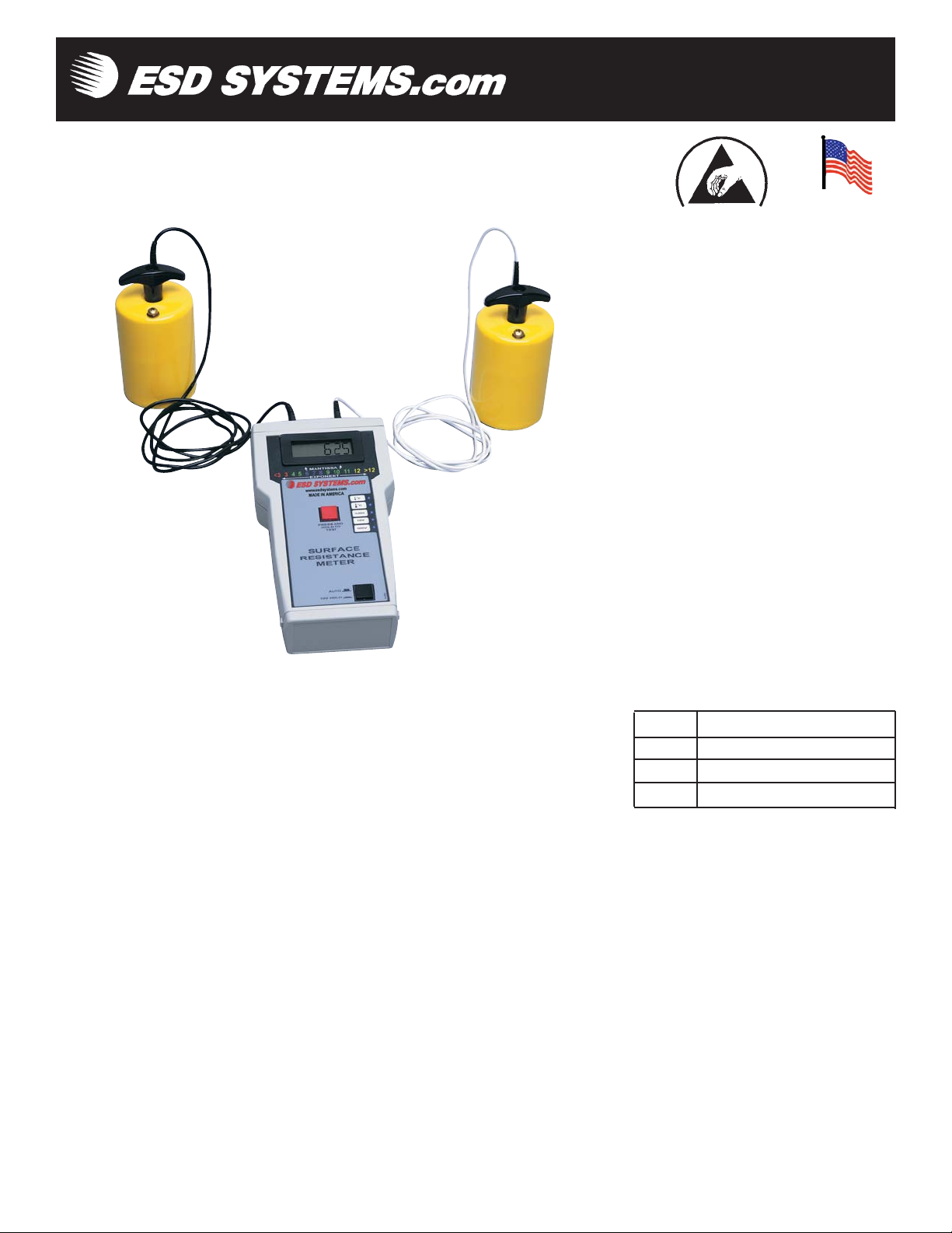
Figure 1. Item 41290 Surface Resistance Test Kit
© 2007 DESCO INDUSTRIES INC.
Employee Owned
Model Description
41290 Surface Resistance Test Kit
41291 Meter & Attachment
41292 Resistivity Attachment
PS-2111 Page 2 of 7
ESD protective products
should be tested:
A. Prior to installation to qualify for
listing in user's ESD control plan
approved ESD protective materials
B. During initial installation
C. For periodic checks of installed
products as part of ESD control plan
compliance verification plan
“A Compliance Verification Plan shall
be established to ensure the
Organization’s fulfillment of the
technical requirements of the ESD
Control Program Plan. Process
monitoring (measurements) shall be
conducted in accordance with a
Compliance Verification Plan that
identifies the technical requirements to
be verified, the measurement limits and
the frequency at which those
verifications shall occur. The
Compliance Verification Plan shall
document the test methods and
equipment used for process monitoring
and measurements. If the test methods
used by the Organization differ from
any of the standards referenced in this
document, then there must be a tailoring
statement that is documented as part of
the ESD Control Program Plan.
Compliance verification records shall be
established and maintained to provide
evidence of conformity to the technical
requirements.
The test equipment selected shall be
capable of making the measurements
defined in the Compliance Verification
Plan.” (ANSI/ESD S20.20-2007 section
7.3)
Electrification Period
The Surface Resistance Test Kit
provides the proper electrification
period of 15 seconds per ESD S4.1,
after numerous readings and
calculations are executed, then displays
surface resistance mantissa
measurement (Note: most analog type
meters display measurements
instantaneously).
When the Test Button is depressed, the
liquid crystal display (LCD) will
indicate:
• Temperature in degrees Fahrenheit
(tolerance ±5°F, typical)
• Temperature in degrees Celsius
(tolerance ±3°C, typical)
• Humidity as percentage (from 5% 95% tolerance, ±10 typical)
• Surface resistance mantissa (with
exponent displayed via LED,
measurement in ohms)
Measurement being displayed is
identified by the illuminated function
LED. The surface resistance exponent
(or power of number) is immediately
illuminated and remains illuminated
measuring the range the surface
resistance in ohms.
Reference Literature
In addition to those noted above:
ANSI/ESD S20.20 - Development of
ESD Control Program
ESD ADV1.0 - Glossary of Terms
ANSI/ESD S6.1 Grounding
These documents can be obtained
directly from the ESD Association, 7902
Turin Rd., Suite 4, Rome, NY 134402069, (315) 339-6937 or www.esda.org.
Other standards are available from the
agencies who produce them. MILHDBK 263A, EIA-IS-5-A,
ASTM-F-150, EN 100015, and EIA-
625. If you need help in obtaining these
documents, please contact our customer
service department.
Features
A. LED Displays: Surface resistance
exponent is displayed via light emitting
diodes illuminating 1/8" high number.
There are 12 LEDs displaying surface
resistance exponent measurement. They
are color coded for quick checks:
Exponent Color
<3, 3 Red
4, 5 Green
6, 7, 8 Blue
9, 10, 11 Green
12, >12 Yellow
Five Function LED’s identify the
measurement being displayed (see B
below).
• When battery voltage drops to
approximately 2 volts, one of the
Function LED's to the right of the red
pushbutton switch will begin to flash,
indicating the need to replace
batteries.
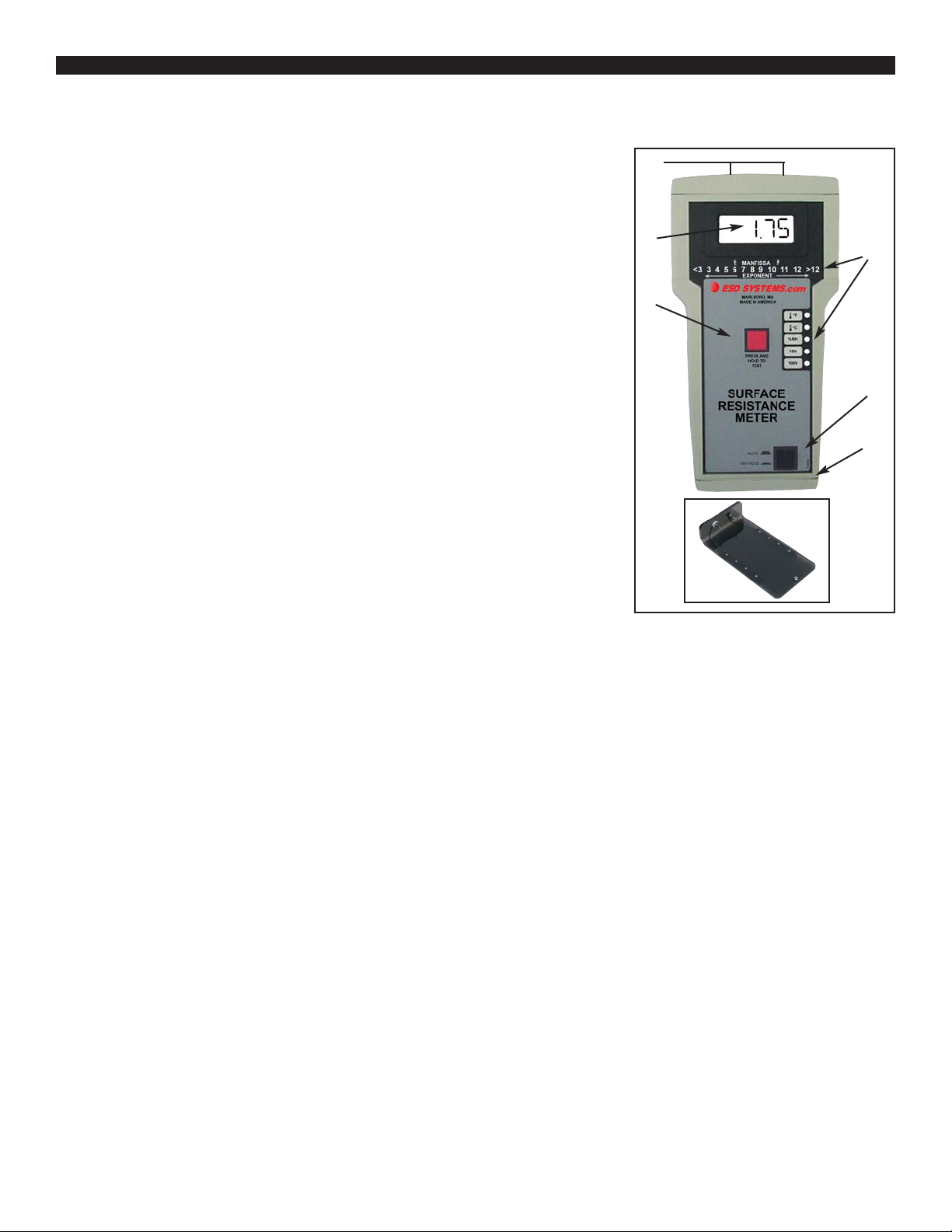
A
B
C
D
E
F
G
© 2007 DESCO INDUSTRIES INC.
Employee Owned
B. Liquid Crystal Display (LCD):
Mantissa is displayed via 9/16" high
liquid crystal display and provides easy
to read resistance (or resistivity)
measurements.
When the Test Button is depressed, the
LCD will indicate:
• Temperature in degrees Fahrenheit
• Temperature in degrees Celsius
• Humidity as percentage
• Surface resistance mantissa (with
exponent displayed via LED,
measurement in ohms)
Surface resistance ohm values are
expressed with a mantissa and exponent
or power of the number. For example, if
"8" is illuminated by its LED and the
LCD displays a mantissa of "7.14", the
measurement is 7.14 x 10E8 ohms or
714,000,000 ohms
If surface is over 10E13 ohms, the
following will appear:
• "1____" on the LCD display indicate
Overrange or that the reading exceeds
the display capabilities
Figure 2. Features of the Surface
Resistance Meter

PS-2111 Page 3 of 7
C. Test Button: This red button
activates electrical power to the Meter.
The exponent or power of the number is
displayed immediately with LED
illuminating number. If "8" is
illuminated, the measurement is in the
10
8
or 10E8 ohm range. To make a
measurement in accordance with ESD
S4.1, the button is to be depressed for
10-20 seconds for the unit to make
numerous readings and calculations.
(Testing in accordance with ESD S4.11997 requires 15 seconds of
electrification; in contrast, most analog
type meters display measurements
instantaneously.) The LCD will display
temperature (F), then temperature (C),
then relative humidity, and then the
surface resistance mantissa. For
example, if the LCD displays a mantissa
of "7.14", and "8" is illuminates by its
LED, the measurement is 7.14 x 10E8
ohms or 714,000,000 ohms.
During the entire period, surface
resistance exponent will be displayed by
LED illuminating number.
D. Override Test Range Voltage
Button: When in the “up” position,
during resistance portion of test, Meter
will automatically switch to the correct
voltage for the resistance range. LED
will illuminate noting selected voltage.
Conductive material 10E5 ohms or less
should be measured at 10 volts.
Dissipative material 10E6 or greater
ohms should be tested at 100 volts. The
button is a switch, which if depressed
will override automatic voltage
selection and test will be performed at
10 volts regardless of resistance level.
E. Jacks: One end of Test Leads has
3.5mm plug (fits Meter left jack). The
3.5mm plug is shielded (identified by
insulated tip and barrel black lead) - see
RTG test procedure: Per ESD S4.1 "The
sensing lead of the resistance meter
shall be connected to groundable point."
One end of Test Lead has standard
banana plug (fits 5# Electrode jack).
F. AA Battery Compartment.
G. Resistivity Parallel Attachment
with Electrodes. (optional Item number
41292)
Cleaning
Per ANSI/ESD S4.1 "Clean the
electrodes with a minimum 70%
isopropanol-water solution." Make sure
conductive pads are dry prior to use.
See specific product test standard for
test lab specimen cleaning instructions.
Per ANSI/ESD S4.1 Worksurfaces "The
test specimens and electrodes shall be
cleaned twice with a minimum 70%
isopropanol-water solution using a
clean, low-linting cloth each time."
(Note: then conditioned for 72 hours,
minimum.)
For installed product periodic testing, do
not clean surfaces. However, if any
measurements lie outside acceptable
range, then clean the surface and re-test.
(Note: for worksurfaces, use ESD
Systems.com Reztore™ Antistatic
Surface and Mat Cleaner (item 10630)
or other ESD cleaner not containing
silicone. Be sure the surface is dry
before testing.
Periodic maintenance - The area
surrounding the cable jacks at the top
end of the meter should be wiped with a
clean cloth moistened with alcohol to
remove skin oils that will accumulate
and affect the accuracy at high
resistances. The frequency of cleaning
will depend on usage; once a month
would be a good starting point. Other
items that should also be cleaned in this
fashion are the cable jackets and the
resistivity attachment, if included.
Power Requirements
The Meter is powered by two
replaceable alkaline AAbatteries.
Battery Replacement
Depress buttons on both sides of bottom
end cap of meter housing. Remove cap,
press on right edge of protruding battery
door, unlatching it, and swing door
open. Carefully replace batteries with
alkaline Type AA. Polarity must be
correct or damage may occur. Close
battery door and re-install bottom end
cap on meter housing.
Test Procedure
General Guidelines:
• Use both 5# Electrodes for RTT
• Use one 5# Electrode and one lead to
groundable point for RTG (note:
groundable points are usually snaps
installed on the material or
workstation)
• Use optional Resistivity Attachment
(removing leads & electrodes) for
Resistivity measurements
• Ensure that item being measured is
electrically isolated (i.e. placed on an
insulative surface) as Meter will
measure lowest resistance path
• Ensure that test leads are separated or
Meter may measure lower resistance
path
• When using 5# Electrodes:
• Place no closer than 2" from edge
of surface being measured
• Place no closer than 3" to any
groundable point
• Place 5# Electrodes 10" apart for
RTT
• Preferred placements include: most
commonly used surface portion,
most worn, center, and furthest
from groundable point.
• For RTG, connect the sensing lead
with shielded plug to groundable
point
• If surface has sections (like floor tiles
or garment panels), for RTT place a 5
pound electrodes on different sections
• Clean surface for Test Lab, but do not
initially clean surface for installed
products (if fails, clean and retest).
Test Lab Test Procedure
Guideline
For test lab use of ESD Worksurfaces,
Floor Materials, Footwear, Garments, or
Seating, best advice is to follow
procedures in applicable ESD
Association standards (see above) which
include details regarding:
• Cleaning (For example per S4.1 "The
test specimens and electrodes shall be
cleaned twice with a minimum 70%
isopropanol-water solution using a
clean, low-linting cloth each time).
Allow to dry.
• Environmental chamber (For example
per S4.1 control relative humidity to
© 2007 DESCO INDUSTRIES INC.
Employee Owned
 Loading...