

ESD SYSTEMS 41201, 41203, 41205 Operation Installation And Maintenance
Tester, Combo, 3-State
Operation, Installation and Maintenance
Pass Range 750K - 10M and 750K - 100M
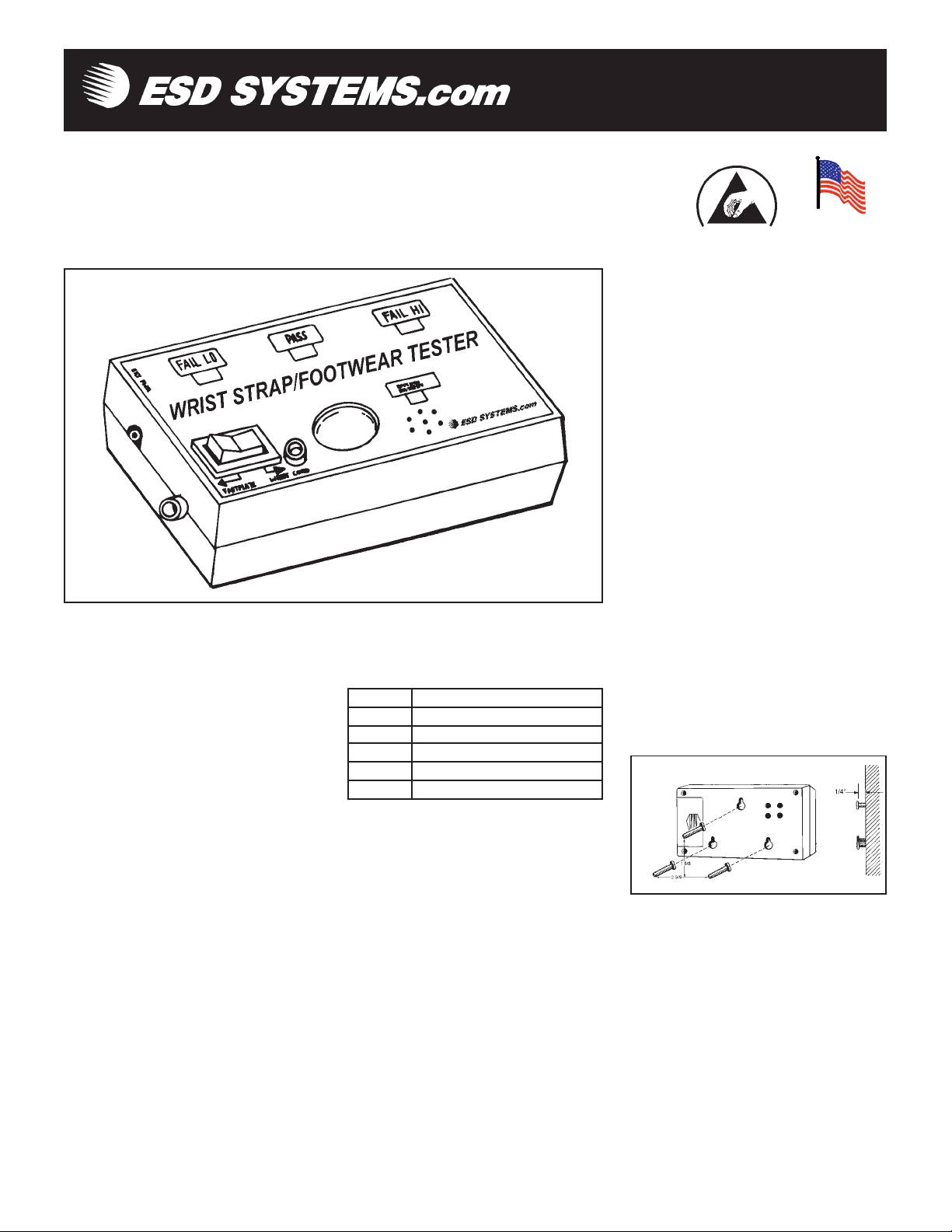
Figure 1. 41201 Combo Tester.
Tester is calibrated to NIST traceable
standards and is available in three models.
CAUTION: Use only the AC adapter
designed for this unit: Item 41228 (120
volt) or Item 41229 (220 volt). Using any
other adapters may damage the unit and
void the warranty.
Inspection
Remove the Tester from the carton and
inspect for damage.
Items included with model 41201:
1 Combo Tester
1 9 volt battery
Items included only with model 41205:
1 Combo Tester
1 Foot plate
1 Ground cord
1 9 volt battery
PS-2057 08/05 Page 1 of 4
Description
The ESD Systems.com 41201 Combo Tester
is a 3-state touch tester designed for fast,
frequent testing of ESD personnel
grounding devices. This product can be used
as one of the tools to fulfill the ANSI ESD
S20.20 paragraph 6.1.3.2 “Compliance
Verification Plan. Verification should
include routine checks of the Technical
Requirements of the Plan.” The Combo
Tester incorporates a unique dual test circuit
design which improves accuracy of testing
and eliminates the need for separate wrist
strap and foot grounder test units. The
41201 is equipped with a 750 Kilohm - 10
Megohm circuit, ideal for testing of wrist
straps and a 750 Kilohm - 100 Megohm
circuit designed for accurate testing of
footwear.
Test parameters are factory set but can be
adjusted to match your own specifications.
The 41201 is very simple to operate. A
green light signals the user that everything
is OK. Ared light and an audible indicator
means that the circuit resistance is either too
low or too high.
The Tester operates on either a 9 volt
battery or a special AC adapter. The Combo
Items included only with model 41203:
1 Combo Tester
1 Base plate
1 Pedestal tube with bracket and boot
installed
1 Banana plug connector
1 Vinyl insulator cap
1 Wall poster
1 5/32" hex wrench
1 9 volt battery
Model numbers 41205 and 41203 are
ideally suited for testing foot grounding
devices.
Installation of Model 41201
The Combo Tester may be used as a
portable unit, or may be permanently
mounted on either a table or a wall. Please
refer to the following instructions when
installing your tester.
Stationary Installation
If you will be using the tester as a portable
unit, you may prefer to mount the unit to a
table or wall. Three keyhole slots on the
back of the unit are included to allow you to
attach the tester to a stationary surface.
Figure 2. Mounting hole locations.
1. Select location for mounting Tester.
Install three #6 or #8 screws spaced as
illustrated in figure 3, into a wall or other
vertical surface. Make sure that the screw
heads do not project out more than 1/4"
from mounting surface. The template on
page four is actual size.
2. Mount the Tester on the screws, pulling
down to lock it in place.
Model Description
41201 Combo Tester
41205 Combo Tester w/ Footplate
41203 Combo Tester w/ Stand
41228 AC Adapter,120V
41229 AC Adapter 220V
Tech Brief
Made in America
© 2005 DESCO INDUSTRIES INC.
Employee Owned
ESD Systems.com • 432 Northboro Road Central Marlboro, MA 01752-1823 • (508) 485-7390 • Fax (508) 480-0257 • Web Site: http://www.esdsystems.com
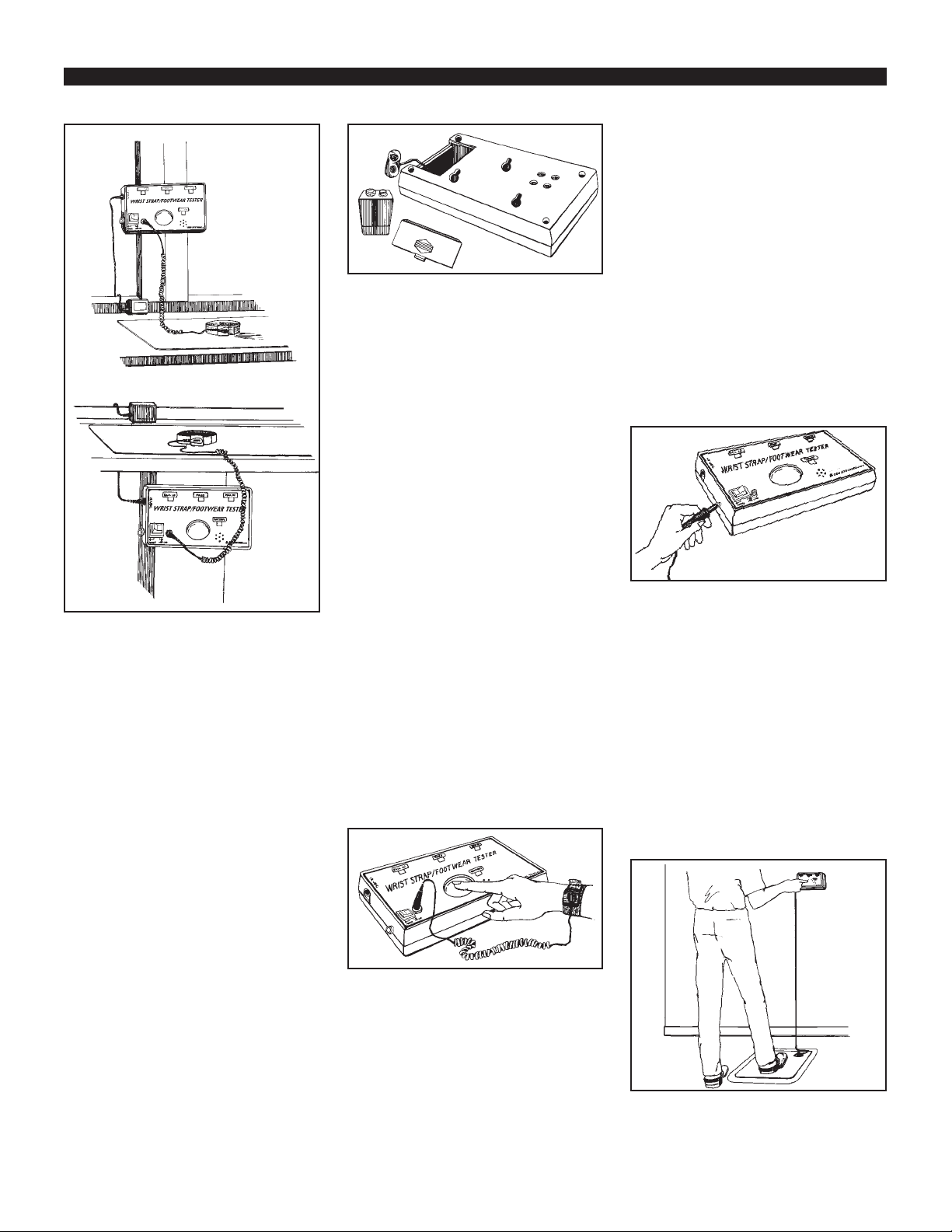
Figure 3. Stationary installation of the
Combo Tester
Operation
The Combo Tester can be operated either on
battery or AC power. The unit comes
equipped with a 9 volt alkaline battery. For
AC operation, plug the optional AC adapter
into the mini phone jack located on the
upper left hand corner of the tester. AC
adapters are sold separately as item 41228
(120 volt) or 41229 (220 volt).
LOW BATTERY INDICATOR
The Combo Tester includes a low battery
indicator alarm circuit. If both the audible
alarm and indicator LED turn on during use,
discontinue testing and replace the battery.
The tester will continue to operate with a
weak battery, but results should not be
considered accurate.
The battery can be easily replaced by
removing the battery compartment cover on
the back of the unit and installing a new 9
volt battery.
Figure 4. Replacing the battery
General Instructions
In the following test configurations, the
41201 can be used to test wrist straps while
they are worn. Models 41205 and 41203
will also allow the user to test footwear.
Insertion of the banana plug on the wrist
strap cord activates the wrist strap tester
circuit and deactivates the footwear test
circuit.
WRIST STRAPTESTING WITH
MODEL 41201
This test safely checks that a continuous
path between the operator, wrist strap and
ground cord exists.
A. While wearing the wrist strap, plug the
banana plug end of the cord into the jack on
the face of the unit.
B. Press rocker switch toward “WRIST
CORD”.
C. Press the test button so that the unit
activates. Hold down for 2-3 seconds while
flexing coil cord area near resistor. Note:
Often the initial intermittency will be failure
of strain relief connection to resistor as
simulated by ESD S1.1-1998 paragraph 5.7.
Bending Life Test.
Note: DO NOT TOUCH ANY OTHER
METAL WHILE PERFORMING TEST.
Figure 5. Testing of wrist strap grounding
assemblies.
D. Lighting of the green “PASS” LED
indicates that the wrist strap and ground
cord assemblies are functioning properly.
E. If either red “FAIL LO” or “FAIL HI”
LEDs light and the audible indicator sounds,
the wrist strap wearer should check the wrist
strap assembly immediately.
PS-2057 Page 2 of 4
TESTING FOOT GROUNDING
DEVICES
In order to test footwear you will need the
model 41205 or 41203 Combo Tester. The
following instructions are intended for use
while wearing foot grounding devices.
When testing conductive shoes, or foot
grounders worn on both feet, test each foot
separately to ensure proper operation and
complete protection.
A. Place the Foot Plate on the floor in front
of the Combo Tester.
B. Plug the plate’s ground cord into the
jack on the left hand side of the unit.
NOTE: Steps Aand B are not required with
the 41203.
Figure 6. Installing ground cord to
“footplate” jack.
C. Press the rocker switch toward
“FOOTPLATE”
D. Place one foot on the plate. If the floor is
conductive, lift the foot you are not testing
off of the floor during this test. Make sure
there is no cord plugged into the “WRIST
CORD” jack.
E. Press the test button so that the unit
activates. Hold for 2-3 seconds.
F. Lighting of the green “PASS” LED
indicates that the foot ground assemblies are
functioning properly.
Figure 7. Testing foot grounding devices
with 41205.
© 2005 DESCO INDUSTRIES INC.
Employee Owned
ESD Systems.com • 432 Northboro Road Central Marlboro, MA 01752-1823 • (508) 485-7390 • Fax (508) 480-0257 • Web Site: http://www.esdsystems.com
 Loading...