

Page 1
PMC-DVI Hardware Manual Rev. 1.0
PMC-DVI
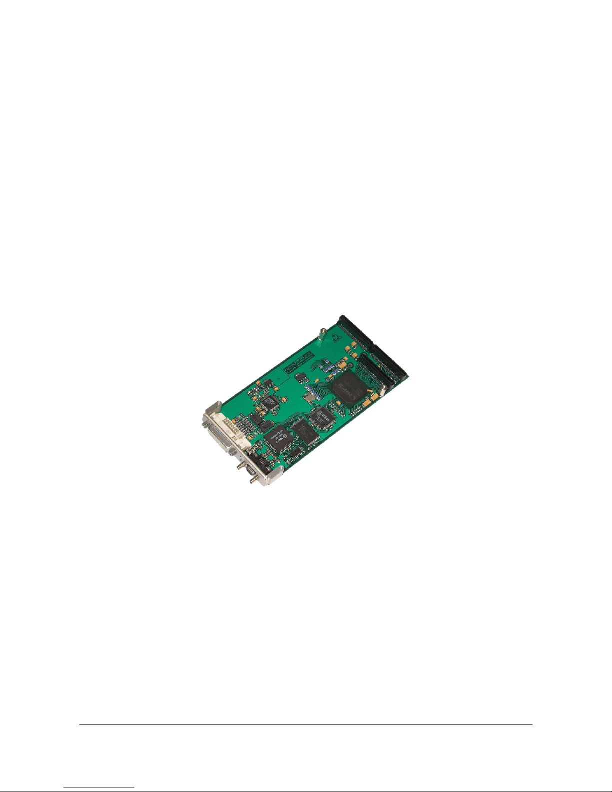
DVI-Graphics Card
Hardware Manual
Page 2
PMC-DVI Hardware Manual Rev. 1.0
Document File:
I:\texte\Doku\MANUALS\PMC\PMC-DVI\Englisch\PMC-DVI_10.en9
Date of Print:
07.04.2003
PCB Version:
PMCVGA Rev. 1.0
Changes in the chapters
The changes in the user’s manual listed below affect changes in the hardware, as well as changes in the
description of the facts only.
Chapter Changes versus previous version
- First version
-
Further technical changes are subject to change without notice.
Page 3

PMC-DVI Hardware Manual Rev. 1.0
N O T E
The information in this document has been carefully checked and is believed to be entirely reliable. esd
makes no warranty of any kind with regard to the material in this document, and assumes no
responsibility for any errors that may appear in this document. esd reserves the right to make changes
without notice to this, or any of its products, to improve reliability, performance or design.
esd assumes no responsibility for the use of any circuitry other than circuitry which is part of a product
of esd gmbh.
esd does not convey to the purchaser of the product described herein any license under the patent rights
of esd gmbh nor the rights of others.
esd electronic system design gmbh
Vahrenwalder Str. 207
30165 Hannover
Germany
Phone: +49-511-372 98-0
Fax: +49-511-372 98-68
E-mail: [email protected]
Internet: www .esd-electronics.com
USA / Canada
esd
PMB 292
20423 State Road 7 #F6
Boca Raton, Florida 33498-6797
USA
Page 4

PMC-DVI Hardware Manual Rev. 1.0 1
Contents
1. Overview .................................................................3
1.1 Description of the PMC-DVI Module .........................................3
1.2 Summary of Technical Data .................................................4
1.2.1 General Technical Data ..............................................4
1.2.2 PCI-Bus .........................................................5
1.2.3 Graphics Card ....................................................5
1.2.4 Software Support ..................................................5
1.2.5 Order Information ..................................................6
2. Hardware Installation .......................................................7
3. Front Panel View with LED-Display ...........................................8
3.1 LEDs and Connectors in the Front Panel ......................................8
4. Connector Assignment ......................................................9
4.1 DVI-I-Connector (X300) ...................................................9
4.2 DSUB-Micro Socket X500, PS2-Mouse and -Keyboard ..........................10
4.3 Assignment of the 64-pole PMC-Connector P11 (Pn1/Jn1 32 Bit PCI) ................11
4.4 Assignment of the 64-pole PMC-Connector P12 (Pn2/Jn2 32 Bit PCI) ...............12
4.5 Assignment of the 64-pole PMC-I/O Connector P14 (Pn4/Jn4 32 Bit PCI) ............13
Page 5

PMC-DVI Hardware Manual Rev. 1.02
This page is intentionally left blank.
Page 6
Overview
PMC-DVI Hardware Manual Rev. 1.0 3
IRQ
PLD
BIOS-EPROM
Digital
Graphics Signals
Graphics
Controller
Asiliant
69030
4 MByte
Memory
DVIConnector
RGB-Analog Signals and DDC
PS2-Keyboard
and Mouse
Interface
9-pole
DSUB-Micro
Connector
PMC-I/OConnector
PMC-
Connector
1. Overview
1.1 Description of the PMC-DVI Module
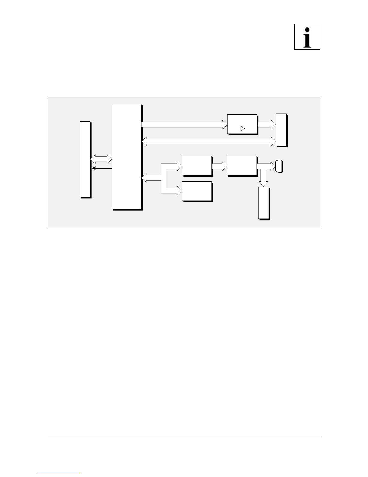
Fig. 1.1: Block-circuit diagram of PMC-DVI Module
The PMC-DVI is a graphics card in ‘Single’ PCI Mezzanine Card format. Keyboard and mouse can be
connected via a PS2-port on a DSUB-Micro socket.
The PMC-DVI module is equipped with a powerful graphics controller 69030 which offers frame rates
from 85 Hz at a resolution of 640x480 (True Colour) to 60 Hz at a resolution of 1600x1200 (16 bit
colours).
The DVI-I-interface can access CRT-monitors via analog video signals as well as TFT-displays via
digital video signals.
The connector of the DVI-I-interface and the connector for the keyboard and the mouse are easy to
access via the front panel.
The LEDs in the front panel show the current status of the PMC-DVI module.
Page 7
Overview
PMC-DVI Hardware Manual Rev. 1.04
1.2 Summary of Technical Data
1.2.1 General Technical Data
Ambient temperature 0...50 °C
Humidity max. 90 %, non-condensing
Power supply
via CompactPCI-Bus,
nominal voltage: 3.3 V,
5 V
Connectors
P11 (64-pol. PMC-connector) - PCI-signals
P12 (64-pol. PMC-connector) - PCI-signals
P14 (64-pol. PMC-connector) - PS2-signals
X300 (DVI24+1, DVI-socket) -
CR T-Monitor and TFT-display
X500 (9-pol. DSUB9-Micro socket) -
PS2-mouse and -keyboard
X200 (8-pole socket, e.g.: CLT-104-02-G-D-BE-A by
Samtec) - only for programming and testing
(ISP-programming)
Dimensions 148.33 mm x 74.04 mm
Fixing four screws M2.5 x 6 mm and distance bolts
Weight 90 g
Table 1.1: General technical data
Page 8
Overview
PMC-DVI Hardware Manual Rev. 1.0 5
1.2.2 PCI-Bus
Host bus PCI-bus according to PCI Local Bus Specification 2.2
PCI-data 32 bit
Controller Asiliant B69030
Interrupt Interrupt signal A
Table 1.2: PCI-bus interface
1.2.3 Graphics Card
Number 1
Outputs
The displays of the digital TFT-display and the analog CRT-monitor
run concurrent and independent from each other
Controller Assiliant B69030
Memory 4 Mbyte on-chip high performance SDRAM
Display Modes
VGA (640x480) with True Colour (24 bit) at 85 Hz
SVGA (800x600) with True Colour at 85 Hz
XGA (1024x768) with High Colour (16 bit) at 85 Hz
SXGA (1280x1024) with 8-bit Colour at 75 Hz
UXGA (1600x1200) with 16-bit Colour at 60 Hz
Table 1.3: Graphics card
1.2.4 Software Support
Graphics drivers for VxW orks, R TOS/UH, Linux and QNX are available for the CPCI-DVI module.
W indows98/NT/2000 is supported as well. Further drivers are available on request.
Page 9
Overview
PMC-DVI Hardware Manual Rev. 1.06
1.2.5 Order Information
Type Properties Order No.
PMC-DVI Graphics card V.2022.02
PMC-DVI-VxW VxWorks driver V.2022.31
PMC-DVI-ME English manual 1*) V.2022.20
PMC-DVI-ENG Engineering manual in English 2*)
Content: circuit layouts, positions of
components and data sheets of important
components
V.2022.25
1*) The manual is free, if it is ordered together with the product.
2*) This manual is liable for costs, please contact our support.
Table 1.4: Order information
Page 10

Installation
PMC-DVI Hardware Manual Rev. 1.0 7
2. Hardware Installation
Because the PMC-DVI module can be inserted to various circuit boards, the carrier system is described
as ‘computer’ in the following.
Attention!
Electro-static discharges may cause damage to electronic components. In order to avoid this please
make sure to follow the steps below before touching the CAN-module:
@ Switch off the power supply of your computer, but leave it connected to mains.
@ Now touch the metal enclosure of the computer to discharge yourself.
@ Even your clothes must not touch the CAN-module.
Installation:
1. Switch off your computer and all connected peripheral devices (monitor, printers, etc.).
2. Discharge yourself as described above.
3. Disconnect the computer from mains.
If the computer is tightly connected to mains and does not have any flexible mains power line,
disconnect the mains via the fuse. Make sure that the fuse cannot be switched on unintentionally.
4. Open the enclosure.
5. Insert the PMC-DVI module to a suitable carrier board.
6. Install the carrier board in the system.
7. Close the enclosure again
8. Connect monitor, mouse and keyboard. An adapter for mouse and keyboard is available.
9. Switch on the power supply of the computer again (power plug or fuse).
10. Switch on the computer, the monitor and the peripheral devices.
8. End of hardware installation.
9. Now, you can configure the PS2-interface. For further information refer to the documentation of
your operating system.
Page 11
Front panel View with LED-Display
PMC-DVI Hardware Manual Rev. 1.08
1
5
9
6
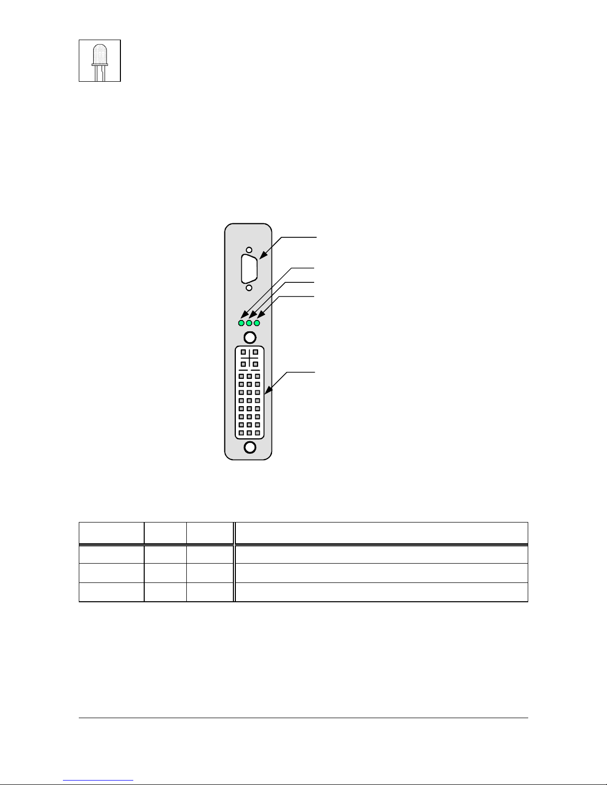
LED D400A (green): Controller
LED D400B (green): PS2-mouse
LED D400C (green): PS2-keyboard
X300
DVI-I-socket
X500
PS2-mouse and PS2-keyboard connector
3. Front Panel View with LED-Display
The Module is equipped with three green LEDs in the front panel.
3.1 LEDs and Connectors in the Front Panel
Fig. 3.1: Front panel view
LED Colour Name Display function (LED on)
LEDD400A green ACT Access to 69030 graphics controller
LEDD400B green MOU Mouse, interrupt
LEDD400C green KEY Keyboard, interrupt
Table 3.1: Display functions of the LEDs
Page 12
Connector Assignment
PMC-DVI Hardware Manual Rev. 1.0 9
1
9
17
8
16
24
C1
C3
C5A
C5B
C2
C4
4. Connector Assignment
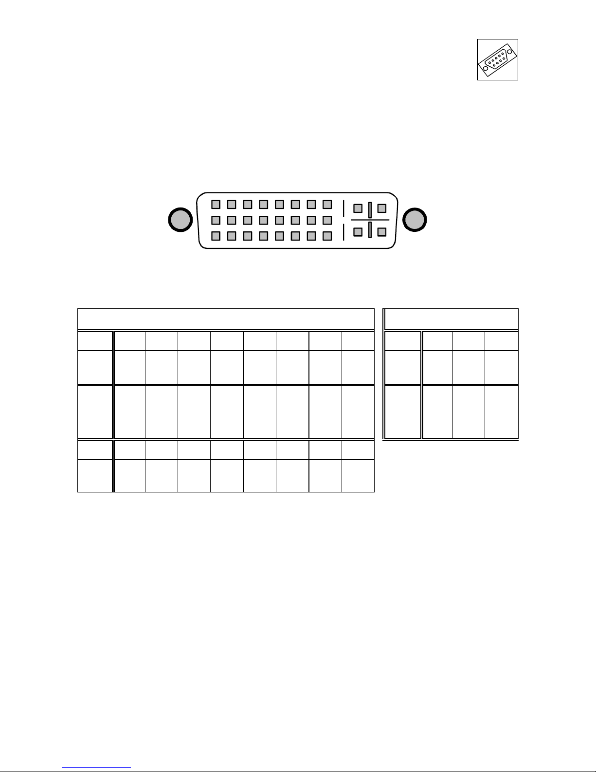
4.1 DVI-I-Connector (X300)
Pin Position:
Pin Assignment:
Digital Signals Analog Signals
Pin 1 2 3 4 5 6 7 8 Pin C1 C5A C2
Signal
DVI_
TX2-
DVI_
TX2+
DVI_
S2/4_
GND
n.c. n.c.
XDDC_
CLK
XDDC_
DATAA_VSYNC
Signal
A_
RED
DAC
GND
A_
GREEN
Pin 9 10 11 12 13 14 15 16 Pin C3 C5B C4
Signal
DVI_
TX1-
DVI_
TX1+
DVI_
S1/3_
GND
n.c. n.c.
XVCC1 XGND1
n.c.
Signal
A_
BLUE
DAC
GND
A_
HSYNC
Pin 17 18 19 20 21 22 23 24
Signal
DVI_
TX0-
DVI_
TX0+
DVI_
S0/5_
GND
n.c. n.c.
DVI_
CLK_
GND
DVI_
TXC+
DVI_
TXC-
Page 13
Connector Assignment
PMC-DVI Hardware Manual Rev. 1.010
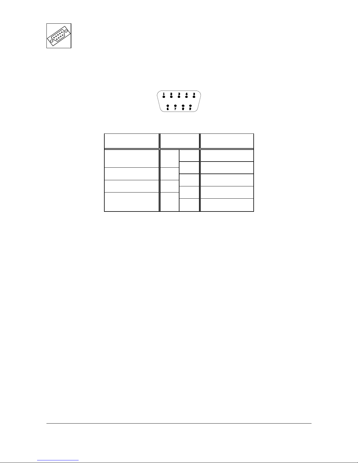
4.2 DSUB-Micro Socket X500, PS2-Mouse and -Keyboard
Pin Position:
Pin Assignment:
Signal Pin Signal
1 XK_DATA
XGND2 6
2 XK_CLK
XVCC2 7
3 XGND2
XVCC2 8
4 XM_CLK
XGND2 9
5 XM_DATA
9-pole DSUB-Micro connector
Signal Description:
XK_DATA,
XK_CLK... keyboard signal lines
XM_DATA,
XM_CLK... mouse signal lines
XVCC2 ... power supply
XGND2 ... reference potential
An adapter for the connection of customary PS2-connectors of mouse and keyboard is available.
Page 14
Connector Assignment
PMC-DVI Hardware Manual Rev. 1.0 11
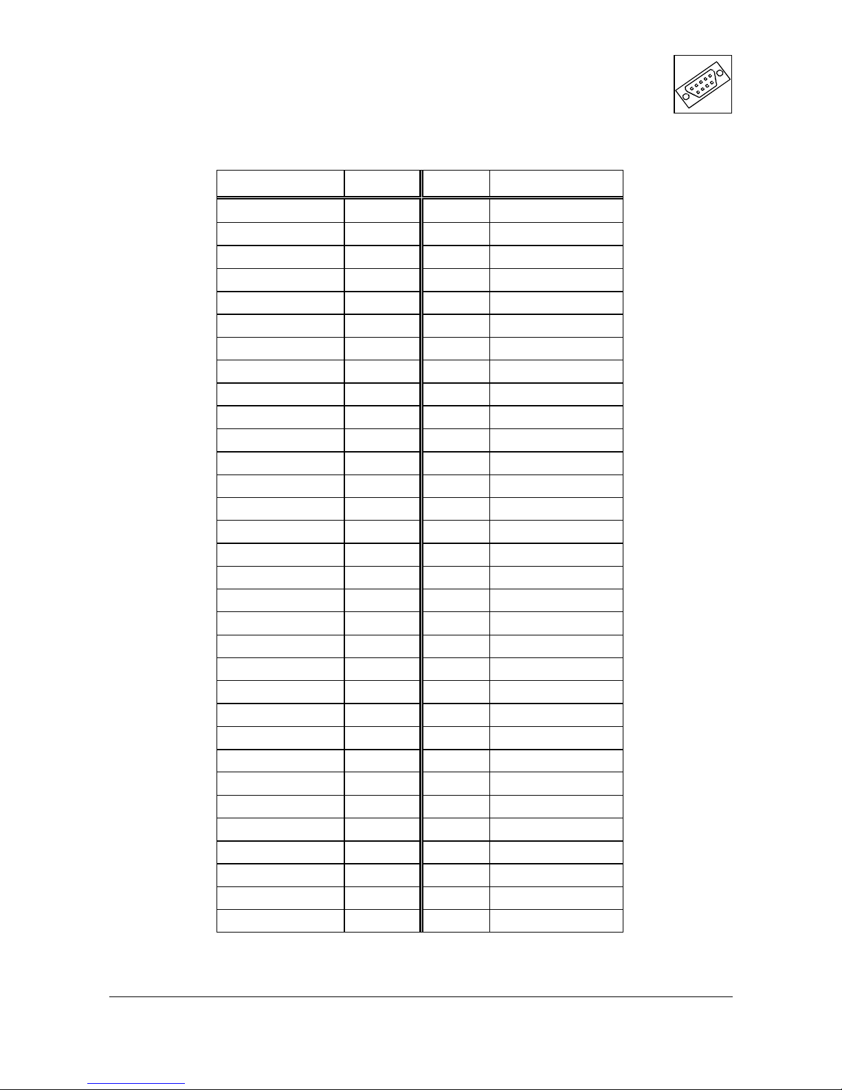
4.3 Assignment of the 64-pole PMC-Connector P11 (Pn1/Jn1 32 Bit PCI)
Signal Pin Pin Signal
n.c. 1 2 -12V
GND 3 4 INTA#
INTB# 5 6 INTC#
GND 7 8 VCC
INTD# 9 10 n.c.
GND 11 12 n.c.
PCLK 13 14 GND
GND 15 16 n.c.
n.c. 17 18 VCC
V IO 19 20 AD31
AD28 21 22 AD27
AD25 23 24 GND
GND 25 26 C/BE3#
AD22 27 28 AD21
AD19 29 30 GND
VIO 31 32 AD17
FRAME# 33 34 GND
GND 35 36 IRDY#
DEVSEL# 37 38 VCC
GND 39 40 n.c.
n.c. 41 42 n.c.
PAR 43 44 GND
VIO 45 46 AD15
AD12 47 48 AD1 1
AD9 49 50 VCC
GND 51 52 C/BE0#
AD6 53 54 AD5
AD4 55 56 GND
VIO 57 58 AD3
AD2 59 60 AD1
AD0 61 62 VCC
GND 63 64 n.c.
Page 15
Connector Assignment
PMC-DVI Hardware Manual Rev. 1.012
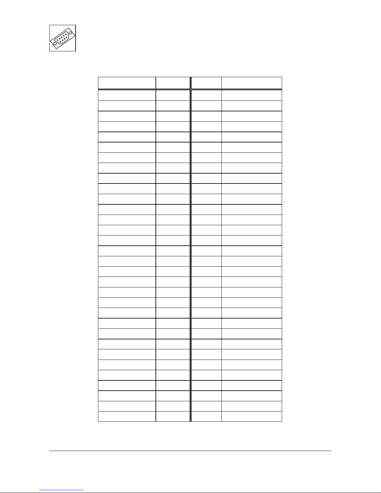
4.4 Assignment of the 64-pole PMC-Connector P12 (Pn2/Jn2 32 Bit PCI)
Signal Pin Pin Signal
+12 V 1 2 n.c.
n.c. 3 4 TDO
TDI 5 6 GND
GND 7 8 n.c.
n.c. 9 10 n.c.
n.c. 11 12 +3,3V
RST# 13 14 n.c.
+3,3V 15 16 n.c.
n.c. 17 18 GND
AD30 19 20 AD29
GND 21 22 AD26
AD24 23 24 +3,3V
IDSEL 25 26 AD23
+3,3V 27 28 AD20
AD18 29 30 GND
AD16 31 32 C/BE2#
GND 33 34 n.c.
TRDY# 35 36 +3,3V
GND 37 38 STOP#
PERR# 39 40 GND
+3,3V 41 42 SERR#
C/BE1# 43 44 GND
AD14 45 46 AD13
GND 47 48 AD10
AD8 49 50 +3,3V
AD7 51 52 n.c.
+3,3V 53 54 n.c.
n.c. 55 56 GND
n.c. 57 58 n.c.
GND 59 60 n.c.
n.c. 61 62 +3,3V
GND 63 64 n.c.
Page 16
Connector Assignment
PMC-DVI Hardware Manual Rev. 1.0 13
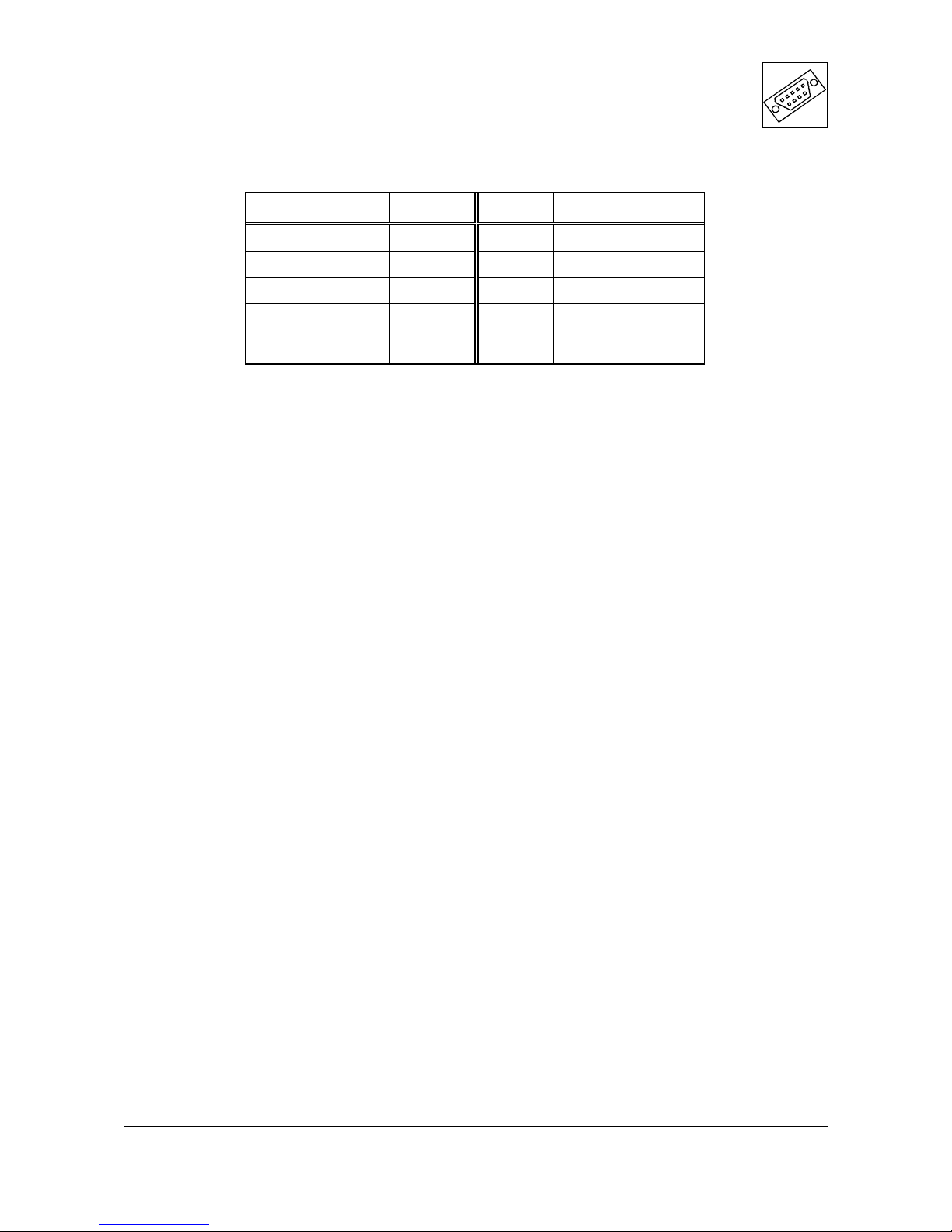
4.5 Assignment of the 64-pole PMC-I/O Connector P14 (Pn4/Jn4 32 Bit PCI)
Signal Pin Pin Signal
M_CLK 1 2 M_DATA
GND 3 4 GND
K_CLK 5 6 K_DATA
n.c.
7
:
63
8
:
64
n.c.
 Loading...