

Page 1
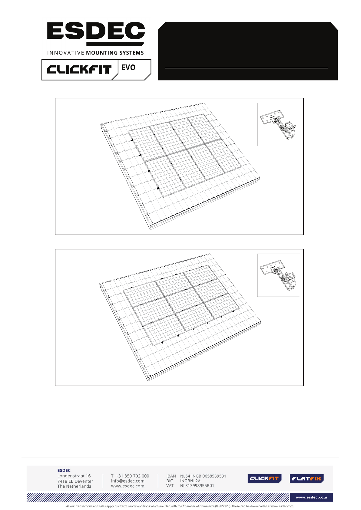
MANUAL
MOUNTING SYSTEM WITH TRUSSHOOK FOR PITCHED ROOF WITH TILES
EN
portrait layout
Rev. 31.10.18
landscape layout
ClickFit Evo mounting system with trusshook for
solar panels, for pitched roofs with roof tiles
© ESDEC BV 2018
Page 2

CONTENTS
page
1. Introduction 1
2. General installation conditions 1
3. Product description 3
4. Parts overview 3
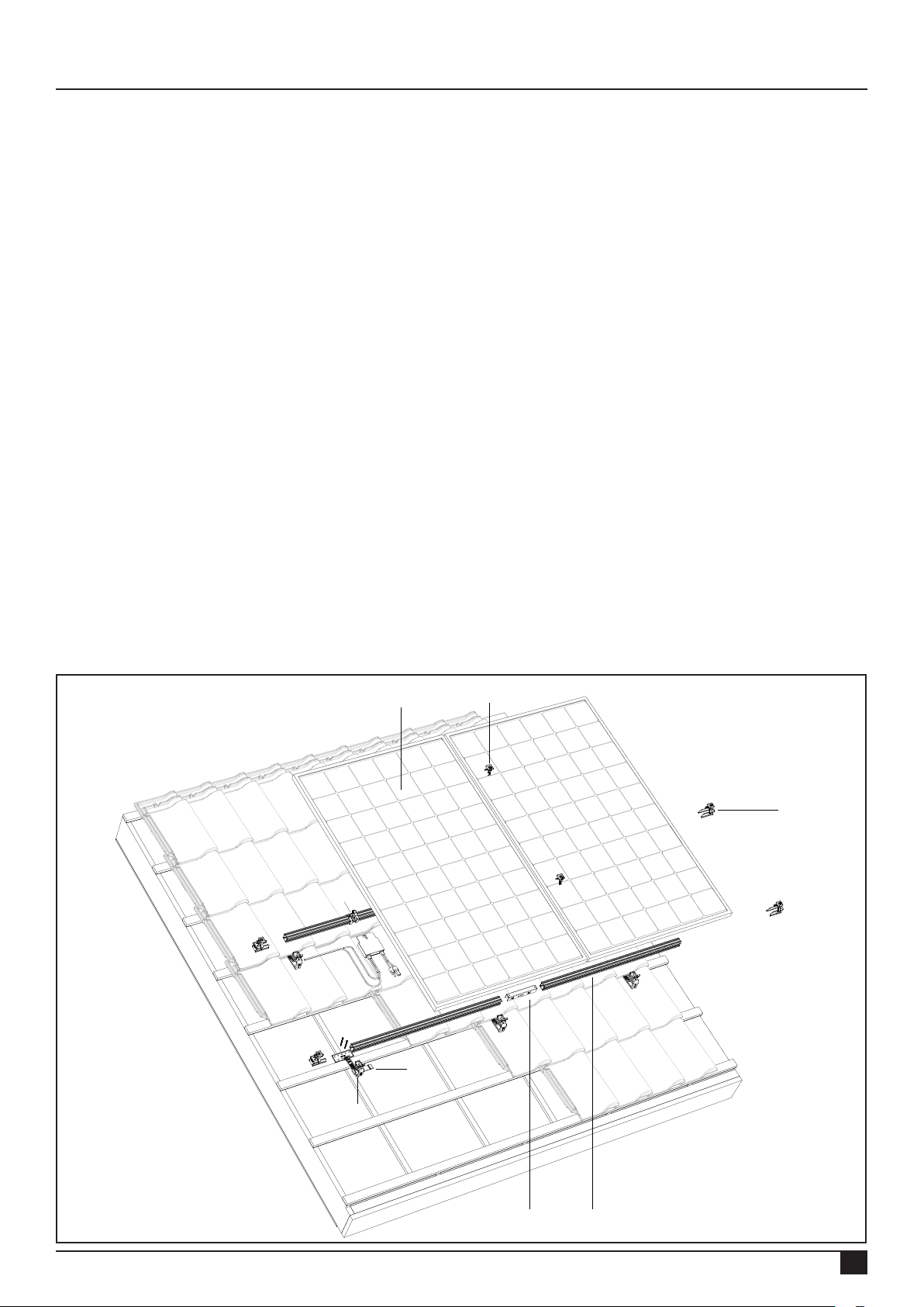
4.1 Exploded-view mounting system in portrait layout 3
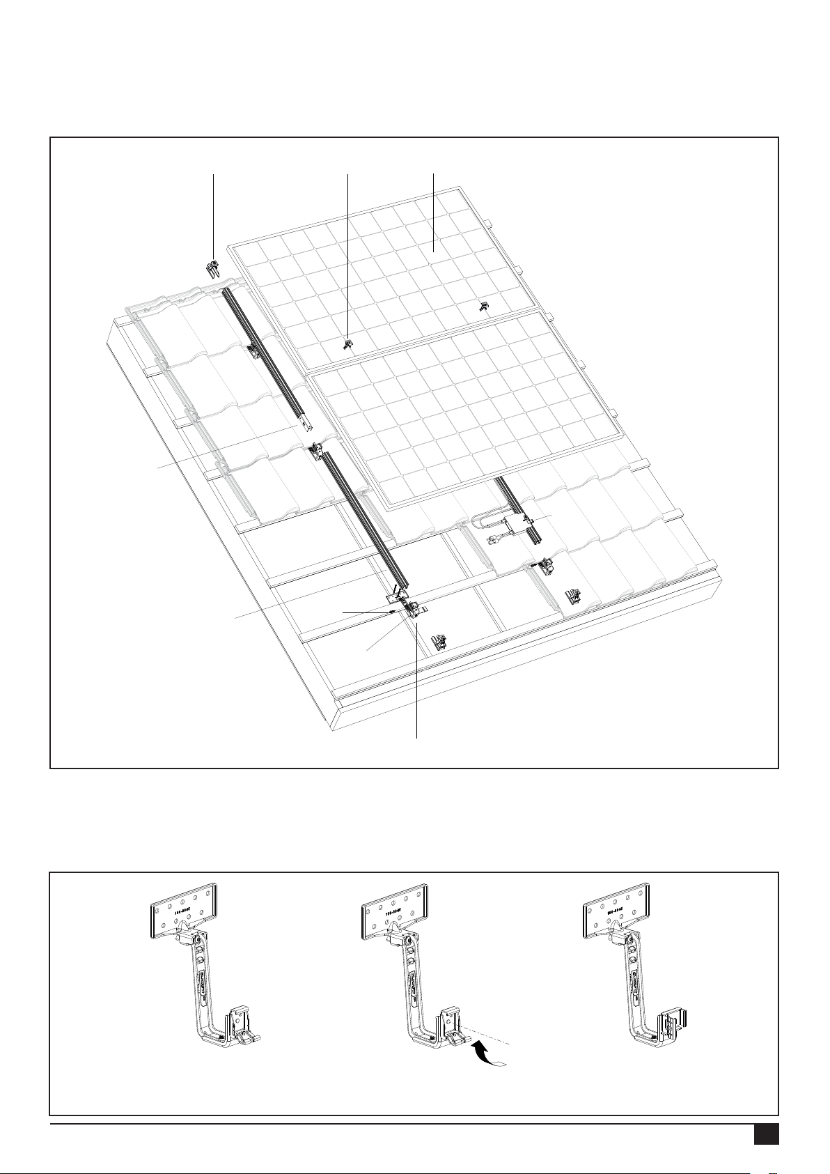
4.2 Exploded-view mounting system in landscape layout 4
4.3 Trusshook for portrait or landscape layout 4
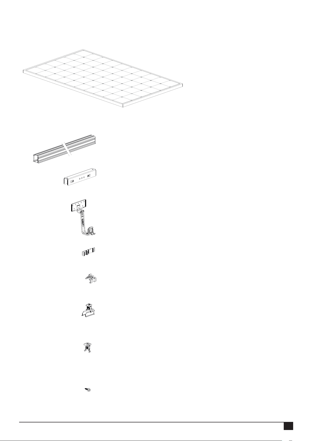
4.4 Parts list 5
5. Mounting preparation 5
5.1 Checking tools and accessories 5
5.2 Cleaning the roof 6
5.3 Determining and measuring the position of the solar panels 7
6. Installation of mounting system in portrait layout 8
6.1 Pre-mounting the mounting rail connector 8
6.2 Fastening trusshooks 9
6.3 Fastening the mounting rail 10
6.4 Mounting the mounting rail cable clip optimizer ready and optimizer 11
(option)
6.5 Mounting the 1st solar panel on the rails 12
6.6 Mounting other solar panels on the rails 13
6.7 Completing the mounting of the 1st row of solar panels 14
6.8 Completing the mounting of several rows under each other 15
7. Installation of mounting system in landscape layout 16
7.1 Pre-mounting the mounting rail connector 16
7.2 Fastening trusshooks 17
7.3 Fastening the mounting rail 18
7.4 Mounting the mounting rail cable clip optimizer ready and optimizer 19
(option)
7.5 Mounting the 1st solar panel on the rails 20
7.6 Mounting other solar panels on then rails 21
7.7 Completing the mounting of the 1st row of solar panel above each other 22
7.8 Completing the mounting of several rows next to each other 23
8. Appendix 24
8.1 Specifications for installation 24
8.2 Tightening moments 25
THIS MOUNTING MANUAL MUST BE CAREFULLY STORED FOR FUTURE USE!
We recommend that you contact your supplier for the duration and conditions relating to guarantees. We also refer you to our
General Terms and Conditions of Sale and Delivery, which are available on request.
The manufacturer rejects all responsibility for damage or injuries caused by failure to meticulously follow this mounting manual and
failure to exercise the usual caution during the transportation, mounting and use of the ClickFit Evo mounting system with trusshook.
As a consequence of constant efforts to improve it may occur that a detail of the product deviates from what is described in this
manual. For this reason, the instructions given serve only as a guideline for the installation of the product specied in this manual.
This manual was created with great care, but the manufacturer cannot accept responsibility for any errors in this manual or their
consequences.
All rights are reserved and nothing in this manual may be copied in any manner whatsoever.
Rev. 31.10.18 MANUAL FOR MOUNTING SYSTEM WITH TRUSSHOOK FOR PITCHED ROOF WITH TILES
Page 3

1. Introduction
This manual describes the installation of the ClickFit Evo mounting system with trusshook on a pitched roof with roof tiles
(for solar panels in portrait and landscape layout).
Read the manual carefully so that you are aware of its entire contents. Follow the instructions in the manual meticulously.
Always execute the actions in the correct sequence.
Store the manual in a safe and dry place. If you lose the manual you can request a new copy from Esdec B.V.
2. General installation conditions
General
Failure to comply with the instructions in this document can result in the nullication of all guarantee and product liability claims.
The information, comments and recommendations in this document are binding and must be checked for completeness and current
relevancy. Esdec BV reserves the right to alter this document without further announcement.
Stability and condition of the roof
The roof must be in good condition and sufciently strong to bear the weight of the solar panels and the additional materials, wind and
snow loads. Check the stability of the roof and alter the roof/construction where necessary. If in doubt, use a construction rm. Ensure
that the load reserve of the roof is not exceeded either completely or at specic points.
Safety warnings
• Mounting the ClickFit Evo mounting system must always be executed by qualied technical personnel (minimum of 2 professionally
qualied persons).
• The addition or omission of parts can have a detrimental effect on the function and is advised against in the strongest terms!
• The roof must be clean, dry, even and free of algae, etc. for placement of the solar panels.
• Avoid mounting if there is a strong wind and a wet roof surface.
• Always work on a pitched roof with a safety harness and safety nets and edge safety if necessary.
• Slide roof tiles upwards so that gaps are created in which you can place your feet. Attention!: Never stand in the gutter.
• Wear shoes with reinforced toecaps and strong anti-slip soles.
• Always wear the correct protective clothing when executing the work.
• Always use a lifting/hoisting installation when moving the material (solar panels, etc.).
• Always place a ladder on a strong and stable surface.
• Always place the ladder at an angle of approximately 75º and allow it to protrude above the edge of the roof.
• If possible, secure the top of the ladder with a rope or tensioning strap.
• Preferably work in accordance with the “working safely on roofs” manual.
• Attention: The trusshook must be placed against the roof batten!
Range of application ClickFit Evo
• Solar panels of all brands and models with a frame height between 30 and 50 mm with a maximum dimension of 2 x 1m (2m2) per
solar panel.
• Range of adjustable trusshook (tiling batten thickness + roof tile thickness): 37 - 62mm
• Wind zone (1 to 3)
• Roof height (3 - 12 m). Contact your supplier if your roof is higher
• Roof covering type: Pitched roof with roof tiles
• Roof incline: Between 15 - 60 degrees (35 degrees is optimum)
Edge zone
The distance from the solar panels to the roof ridge and the gutter must be a minimum of 30 cm, in consideration of the wind load.
The distance from the solar panels to the side of the roof must be a minimum of 30 cm. Solar panels may not be placed here either
completely or partially.
Rev. 31.10.18 MANUAL FOR MOUNTING SYSTEM WITH TRUSSHOOK FOR PITCHED ROOF WITH TILES
01
Page 4

Standards, prescriptions and regulations
When installing the mounting system, it is important to follow the mounting manual and meet the accompanying standards
in order to prevent accidents. In particular, take account of the following standards, prescriptions and regulations:
• Buildings Decree Construction
• PPE Personal Protective Equipment
• KEMA Inspection of Electrotechnical Materials
• DIN 1055 Design loads for buildings
• DIN 18299 General rules for all building sectors
• DIN 18451 Scaffolds
Removal and disassembly
Remove the product in accordance with the local laws and regulations.
Guarantee
Guarantee in accordance with guarantee conditions and general terms and conditions of Esdec BV. These can be viewed
at the website www.esdec.com.
Liability
The manufacturer does not accept any liability whatsoever for damage and or injury caused by failure to (stringently)
comply with the safety regulations and instructions in this manual, or due to inattentiveness during the installation of the
product specied in this document and any accompanying accessories.
• Printing errors reserved
Rev. 31.10.18 MANUAL FOR MOUNTING SYSTEM WITH TRUSSHOOK FOR PITCHED ROOF WITH TILES
02
Page 5
3. Product description
The ClickFit Evo mounting system consists of the patented adjustable trusshooks, mounting rails and the mounting
materials necessary to mount the solar panels on a tiled roof in portrait or landscape layout. The trusshook has a rotatable
click bracket that enables the mounting rails to be clicked onto the trusshook both horizontally and vertically. The ClickFit
Evo mounting system for tiled roofs can be used for all roof tiles, regardless of their type.
Roof fastening
The universal roong tiles are fastened to the roof battens with a minimum of 2 teller head screws. Every trusshook has
9 mounting holes, which makes the position of the trusshook on the roof batten laterally adjustable.
Differences in height in the roof can easily be bridged with the aid of the adjustable trusshook.
Fastening the mounting rail
The mounting rail is fastened to the trusshooks by means of a click connection. No further materials or tools are required for
this.
Fastening the panels
The solar panels are fastened to the mounting rails with the aid of the universal module clamps.
4. Parts overview
4.1 Exploded-view mounting system in portrait layout
1 8
6
7
5
4
23
Rev. 31.10.18 MANUAL FOR MOUNTING SYSTEM WITH TRUSSHOOK FOR PITCHED ROOF WITH TILES
03
Page 6
4.2 Exploded-view mounting system in landscape layout
7 8 1
3
6
2
9
5
4
4.3 Trusshook for portrait or landscape layout
The trusshook has rotatable click bracket so that the mounting rail can be clicked onto the trusshook both vertically and
horizontally. This allows the trusshook to be applied for both portrait and landscape layouts.
Trusshook with click bracket
in portrait layout
Rev. 31.10.18 MANUAL FOR MOUNTING SYSTEM WITH TRUSSHOOK FOR PITCHED ROOF WITH TILES
Trusshook with click bracket
in landscape layout
04
Page 7
4.4 Parts list
1. Solar panel
2. ClickFit Evo Mounting rail
Article no: 100-800_
3. ClickFit Evo Mounting rail connector
Article no: 100-8061
4. ClickFit Evo trusshook
Article no: 100-80
5. ClickFit Evo trusshook lling rubber
Article no: 100-8063
6. ClickFit Evo Mounting rail cable clip optimizer ready
Article no: 100-8062
7. ClickFit Evo Mounting rail end cap grey
Article no: 100-8060
7B. ClickFit Evo Mounting rail end cap black
Article no: 100-8060-B
8. ClickFit Evo Universal module clamp grey
Article no: 100-8020
8B.ClickFit Evo Universal module clamp black
Article no: 100-8020-B
9. Self-tapping sheet metal
screw Article no: 100-3010
(for landscape)
Rev. 31.10.18 MANUAL FOR MOUNTING SYSTEM WITH TRUSSHOOK FOR PITCHED ROOF WITH TILES
05
Page 8
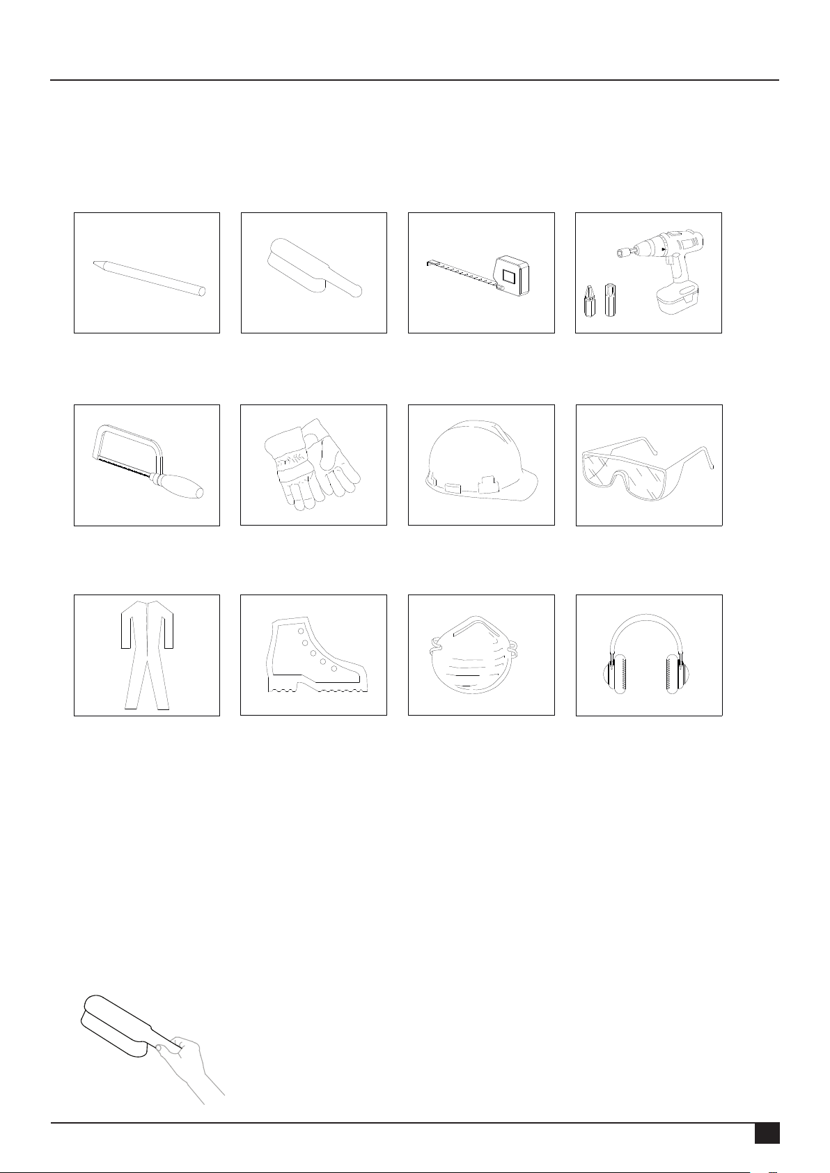
5. Mounting preparation
5.1 Checking tools and accessories
Here is a list of the required tools/aids:
Marker / chalk Brush Tape measure Battery-powered drill
T30
Metal saw Safety gloves
Safety shoes Mouth mask Hearing protectionSafety clothing
Scaffold or stable safe
ladder
Safety helmet
Safety glasses
5.2 Cleaning the roof
Clean the roof tiles on the pitched roof with a brush.
Remove algae, moss, etc. to limit unevenness to a minimum during the installation!
Rev. 31.10.18 MANUAL FOR MOUNTING SYSTEM WITH TRUSSHOOK FOR PITCHED ROOF WITH TILES
06
Page 9
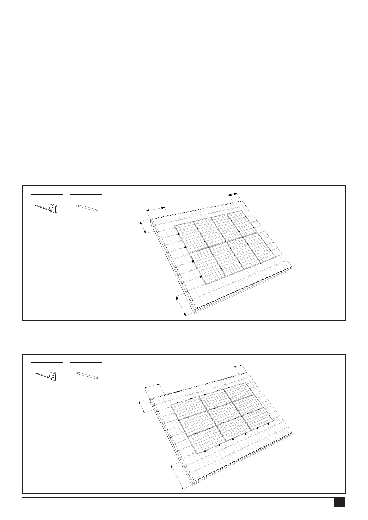
5.3 Determining and measuring the position of the solar panels
When determining the position of the solar panels on the pitched roof it is very important to pay attention to the amount of
sunlight received during the entire day and during the entire year. Place the panels on a roof surface that is not shaded. The
shadows of a chimney, dormer window, trees and nearby buildings have a detrimental effect on the yield of the solar panels.
Measuring and marking
For the placement of the solar panel (in the portrait or landscape layout) you need a space of approximately 160x80 cm or
160x100 cm or 200x100 cm per panel (depending on the type of solar panel).
Ensure that a minimum of 30 cm is kept free all around the solar panels on the roof. This means 30 cm from the roof ridge
and the gutter, and 30 cm from the sides in connection with turbulent wind loads.
Mark the contours of the panel eld on the tiles with a marker pen or chalk.
Marking mounting rails and trusshooks for portrait layout:
Mark the position of the mounting rails: on ¼ of the top and bottom edges of the panel.
Now mark where the trusshooks must be placed. The trusshook distance depends on several variables (wind load, building
height, location, condition of the roof, etc.). Follow the instructions given by the calculator with regard to the gaps between
each trusshook. They are an important guide. The maximum lateral gap is 1.20 m.
min. 30 cm
min. 30 cm
min. 30 cm
min. 30 cm
Marking mounting rails and trusshooks for landscape layout:
Mark the lines for the mounting rail placement: on 1/4 of the panel side edges. Now mark where the trusshooks must be
placed.
min. 30 cm
min. 30 cm
min. 30 cm
min. 30 cm
Rev. 31.10.18 MANUAL FOR MOUNTING SYSTEM WITH TRUSSHOOK FOR PITCHED ROOF WITH TILES
07
Page 10
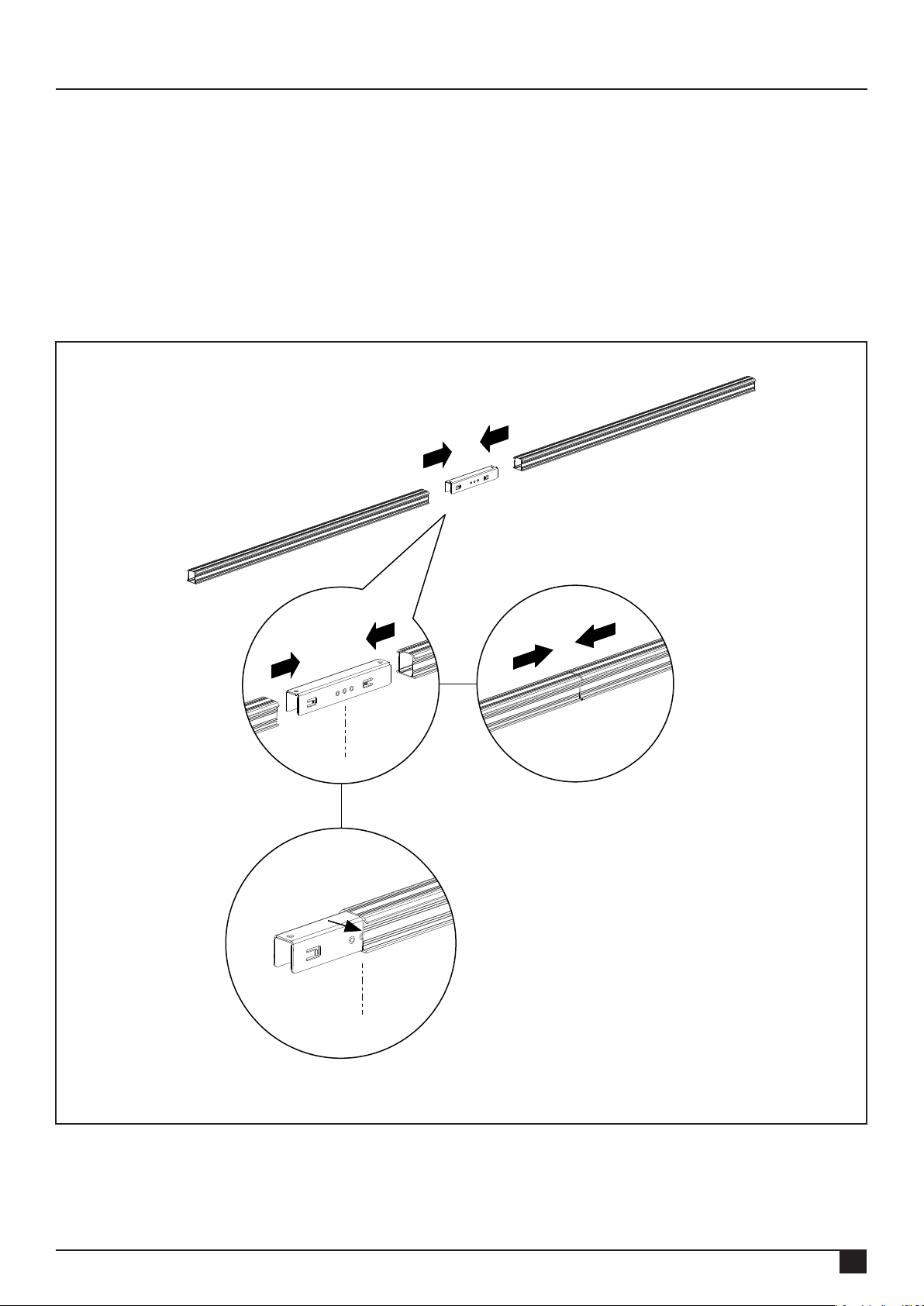
6. Installation of mounting system in portrait layout
6.1 Pre-mounting the mounting rail connector
First determine the rail length required for the row of solar panels.
You can connect the mounting rails to each other with mounting rail connectors. There are small clamps with teeth on the
mounting rail connector that grip the inside of the rail.
Slide the connector into the ends of the mounting rail. Slide the connector to the centre of the middle stud of the connector.
Connect the number of rails to each other until the total required rail length is reached.
Attention! See appendix for restrictions and other details.
Rev. 31.10.18 MANUAL FOR MOUNTING SYSTEM WITH TRUSSHOOK FOR PITCHED ROOF WITH TILES
08
Page 11
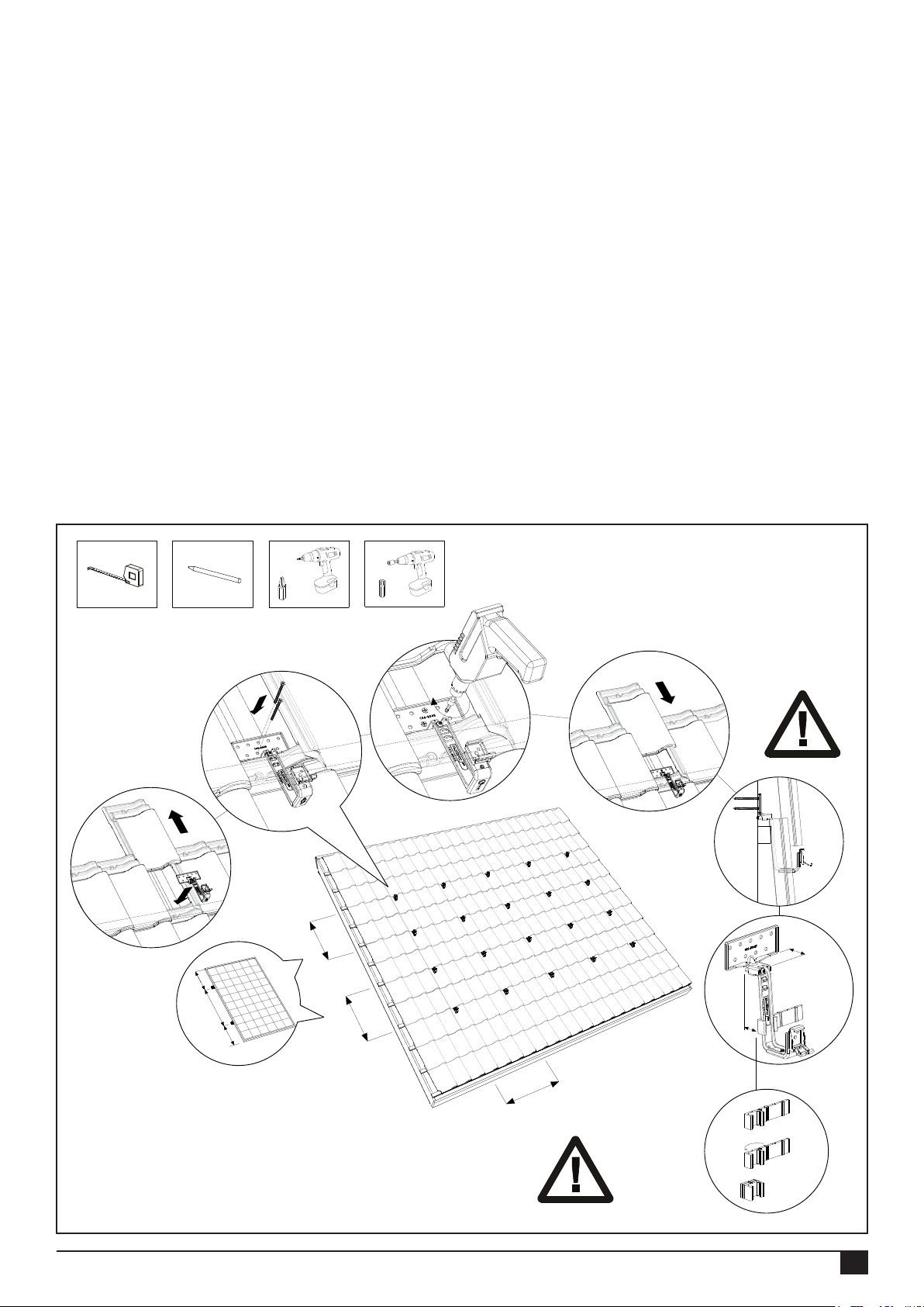
6.2 Fastening trusshooks
1. Slide the tile above the trusshook upwards, under the tile on top of it. Place the mounting ange of the trusshook on the
roof batten, ensure that it connects correctly and pull the trusshook against the tile. Place the trusshook in the concave part
(dip) of the underlying tile. The top adjustable part of the trusshook is a minimum of 37 mm and a maximum of 62 mm.
2. Fasten the trusshook with a minimum of 2 teller head screws 6x50/60 to the roof batten. Attention! These screws are not
supplied.
3. Tighten the torx screw on the top of the trusshook rmly with a cordless screwdriver. Attention! The tightening moment
of the screw connection is 4.5 Nm.
4. Slide the tile above the trusshook down again. With some roof tiles the top tile must be adapted to the trusshook with an
angle grinder or a le so that the tiles close correctly again. *
5. Follow the instructions given by the calculator with regard to the gaps between each trusshook. They are an important
guide. The maximum lateral gap is 1.20 m. Divide the number of trusshooks produced by the calculation over possible roof
battens, with a maximum span of 1.20m. Ensure that the trusshooks are aligned with each other.
*Option: For tiles with a high water retaining edge, the lling rubber can be placed under the trusshook so that it rests neatly
on the tile. Fold the rubber to produce the desired thickness. The lling steps are 5,10 and 15 mm.
Attention! Ensure that the click bracket on every trusshook is in the correct position so that the mounting rail can be
fastened to the trusshook horizontally (see chapter 5.3).
1
1/4H
2/4H
2
1/4H
T30
3
4
4,5 Nm
Min. 2x
5
2/4H
37-62 mm
2/4H
See calculator
Max. 1,20 m.
Rev. 31.10.18 MANUAL FOR MOUNTING SYSTEM WITH TRUSSHOOK FOR PITCHED ROOF WITH TILES
OPTION
09
Page 12
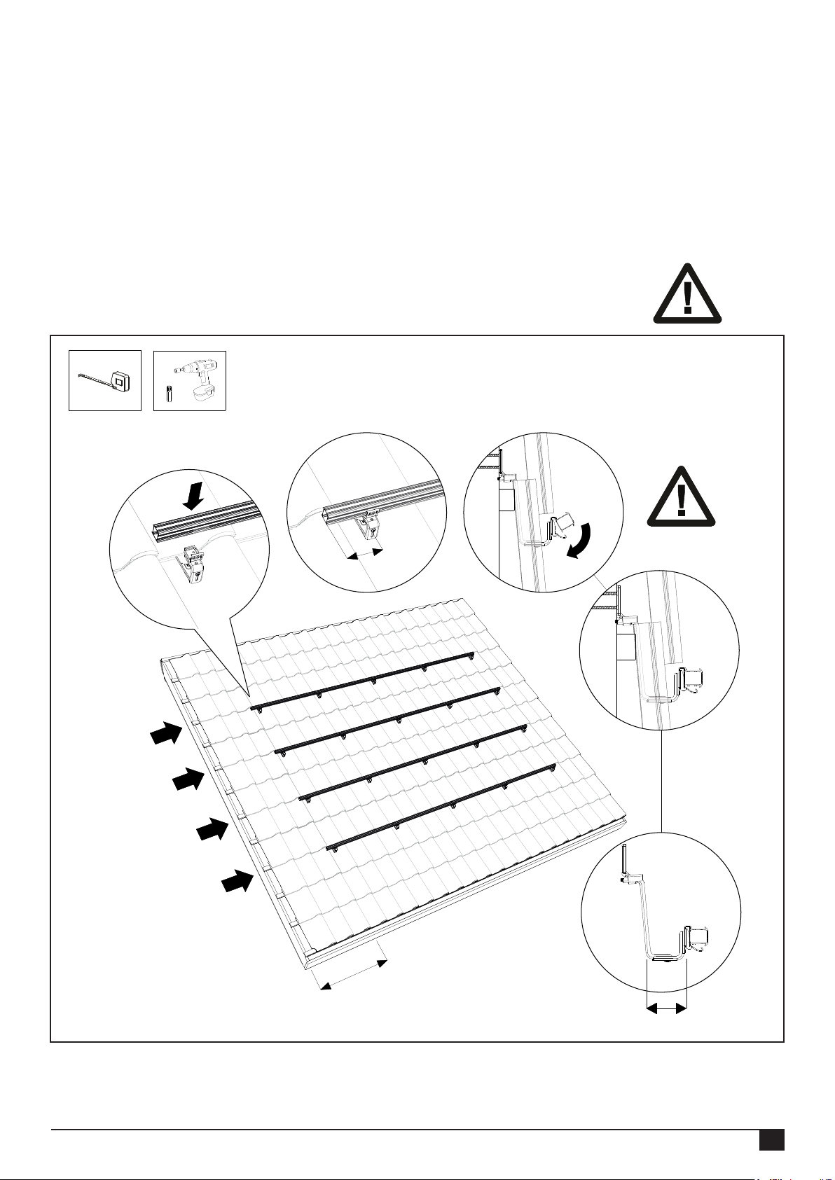
6.3 Fastening the mounting rail
1. Place the mounting rail in the installed trusshooks.
2. Ensure that the end of the mounting rail protrudes 90 - 250 mm from the last trusshook.
3. Now click the mounting rail onto the trusshooks. Ensure that it clicks on rmly.
4. Ensure that the mounting rail and the trusshooks are correctly aligned with each other and the mounting rail is positioned
correctly on the trusshook. Ensure that the mounting rails are directly above each other in connection with the alignment of
the solar panels!
5. The mounting rails can be aligned if necessary by means of the height adjustment on the trusshook. Slightly unscrew the
torx screw on the underside of the trusshooks. Adjust the desired height and tighten the torx screws again. Attention! The
tightening moment of the screw connection is a minimum of 6 Nm.
Attention! See appendix for restrictions and other details.
T30
1
4e
3e
2e
2
min. 90 mm
3
Click!
4
1e
min. 30 cm
Rev. 31.10.18 MANUAL FOR MOUNTING SYSTEM WITH TRUSSHOOK FOR PITCHED ROOF WITH TILES
68 - 98 mm
10
Page 13
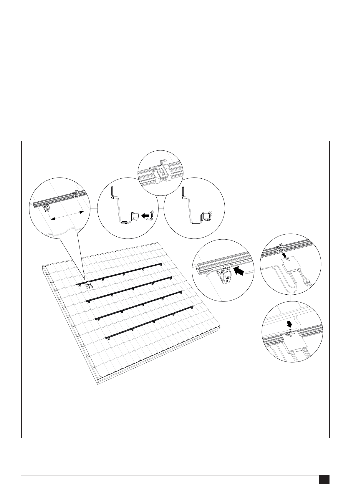
6.4 Mounting the mounting rail cable clip optimizer ready and optimizer (option)
1. Position the cable clip on the top mounting rail of a row. One cable clip is used per solar panel. The cable clips are under
the middle of the panel. Place the cable clips approximately 1m from each other.
2. Click the cable clip onto the mounting rails.
3. Lead the cabling through the click bracket of the trusshook and the cable clip.
Optional:
4. Click the optional optimizer onto the cable clip.
5. Lead the cables of the optimizer through the cable clip.
Attention! See appendix for restrictions and other details.
21
30 cm
Click!
4
3
5
Click!
Rev. 31.10.18 MANUAL FOR MOUNTING SYSTEM WITH TRUSSHOOK FOR PITCHED ROOF WITH TILES
11
Page 14
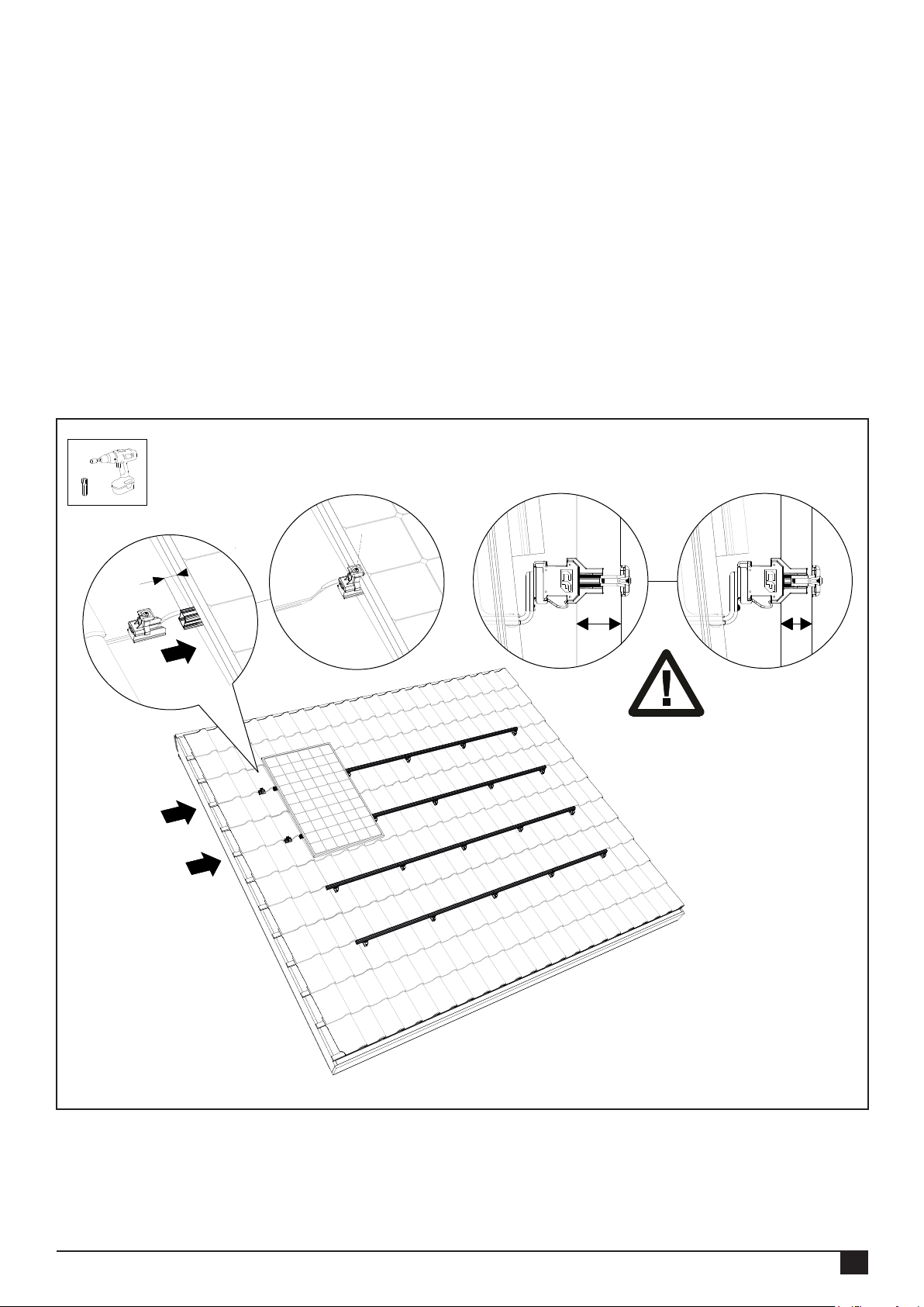
6.5 Mounting 1st solar panel on the mounting rails
Mounting aid (Option):
Click the mounting aid (2x) onto the frame on the back of the solar panel. Use the mounting holes at the top of the frame for
this. Click the cables of the solar panel securely into the cable clamp on the mounting aid.
Hang the solar panel, including the mounting aid, on the mounting rail. Click the cables of the solar panel into the cable clip
that has already been placed. Slide the rst solar panel to the side of the mounting rail. Leave 20 - 35 mm of rail protruding
visibly beside the solar panel.
Now slide the mounting rail end cap with universal module (end) clamp onto the mounting rail. Choose the correct recess so
that the universal module (end) clip connects to the solar panel. Now tighten the universal module (end) clamp.
Attention! The tightening moment of the screw connection is 4.5 Nm.
Attention! The minimum panel thickness Y = 30 mm and the maximum panel thickness X = 50 mm.
Attention! See appendix for restrictions and other details.
T30
1
20 - 35 mm
2
X
Y
Rev. 31.10.18 MANUAL FOR MOUNTING SYSTEM WITH TRUSSHOOK FOR PITCHED ROOF WITH TILES
12
Page 15
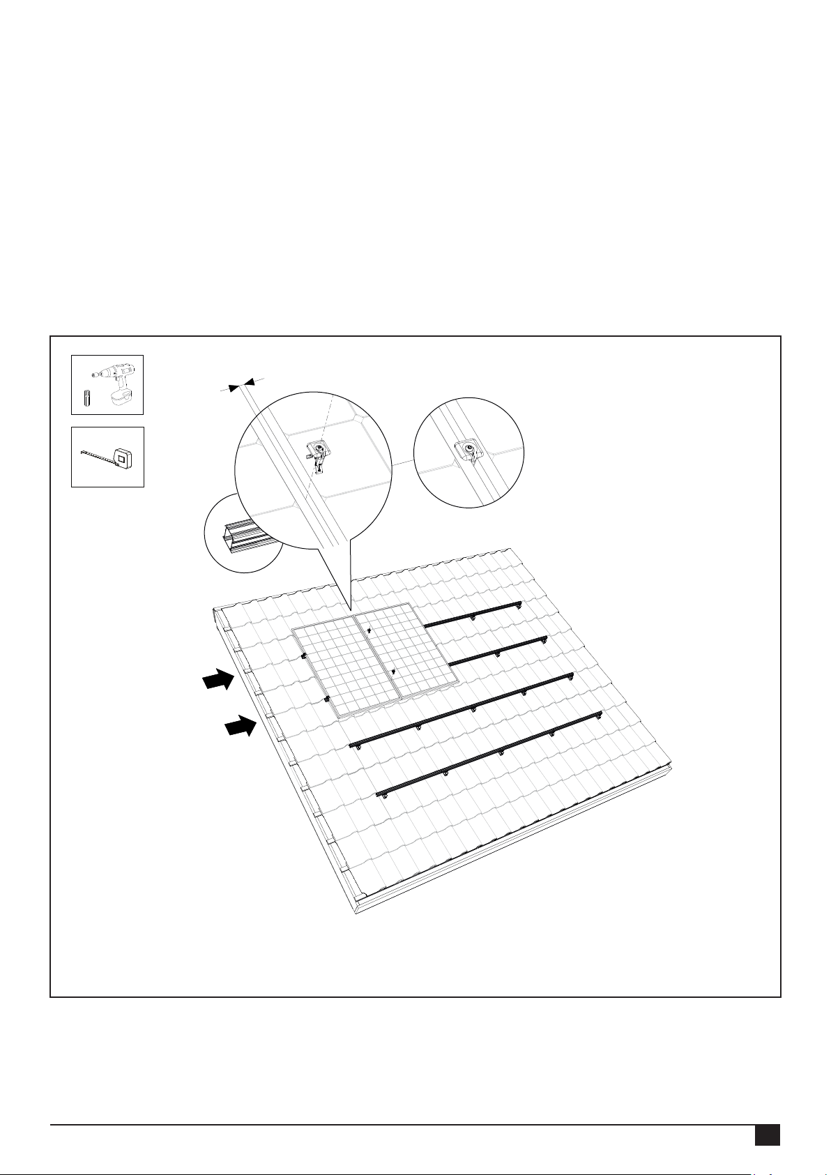
6.6 Mounting other solar panels on the mounting rails
Click the universal module clamps onto the mounting rails. Slide them against the rst solar panel. Place the second solar
panel on the mounting rail, click the cables of the solar panel securely into the cable clip and slide the solar panel to the rst
against the universal module clamp. Now tighten the universal module clamp screw.
Attention! The tightening moment of the screw connection is 4.5 Nm.
Ensure that the solar panels are lying completely straight before you tighten the torx screw! Repeat this with the remaining
solar panels.
Attention! See appendices for restrictions and other details.
12 mm
T30
Rev. 31.10.18 MANUAL FOR MOUNTING SYSTEM WITH TRUSSHOOK FOR PITCHED ROOF WITH TILES
13
Page 16
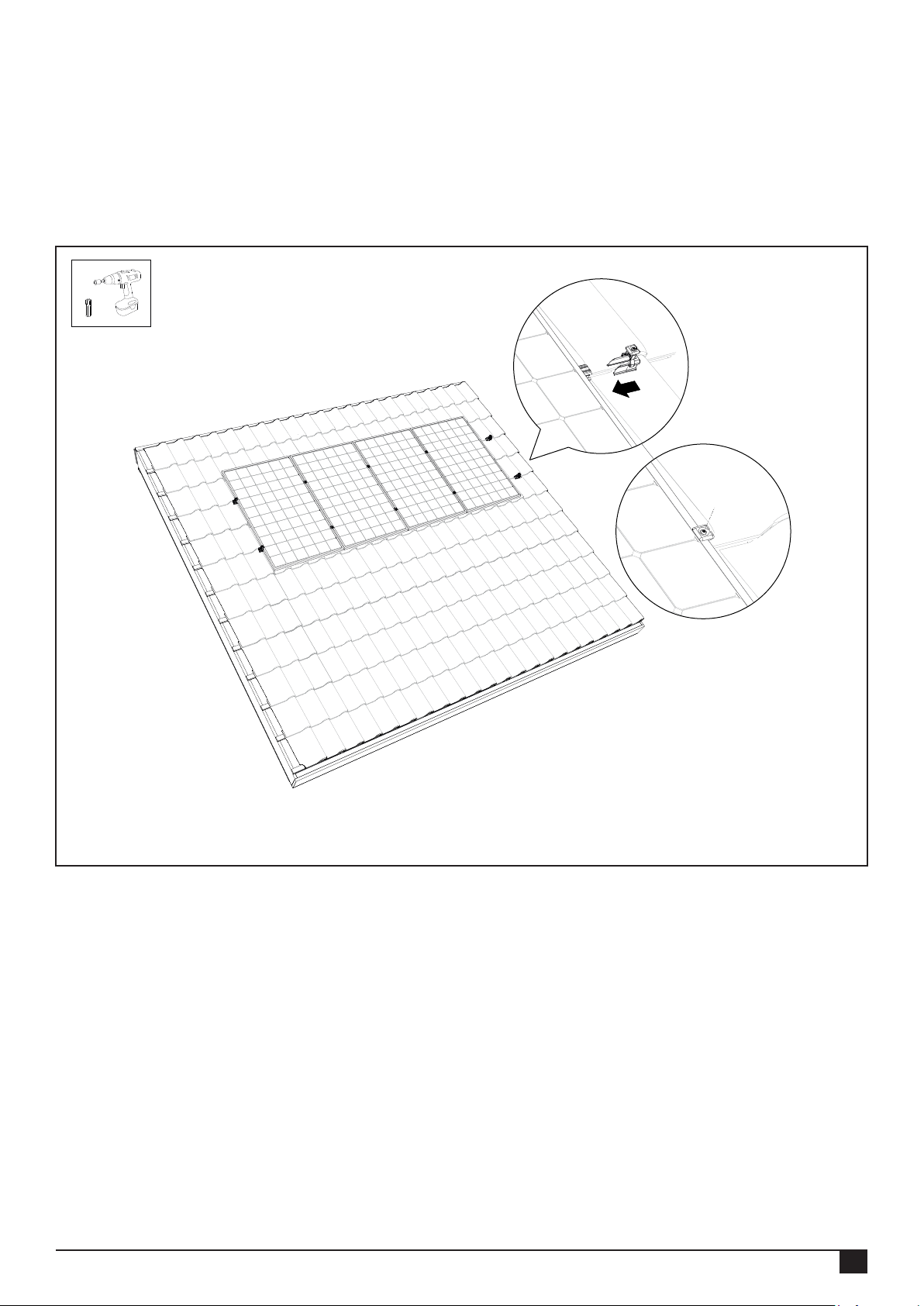
6.7 Completing the mounting of the 1st row of solar panels
1. Allow the mounting rail to protrude 20 - 35 mm from the edge of the solar panel. Slide the mounting rail end cap with
universal module (end) clip onto the mounting rail. Attention! Choose the correct recess so that the end clip connects to the
solar panel.
2. Now screw the end clip tight with the torx screw. Attention! The tightening moment of the screw connection is 4.5 Nm.
T30
Rev. 31.10.18 MANUAL FOR MOUNTING SYSTEM WITH TRUSSHOOK FOR PITCHED ROOF WITH TILES
14
Page 17
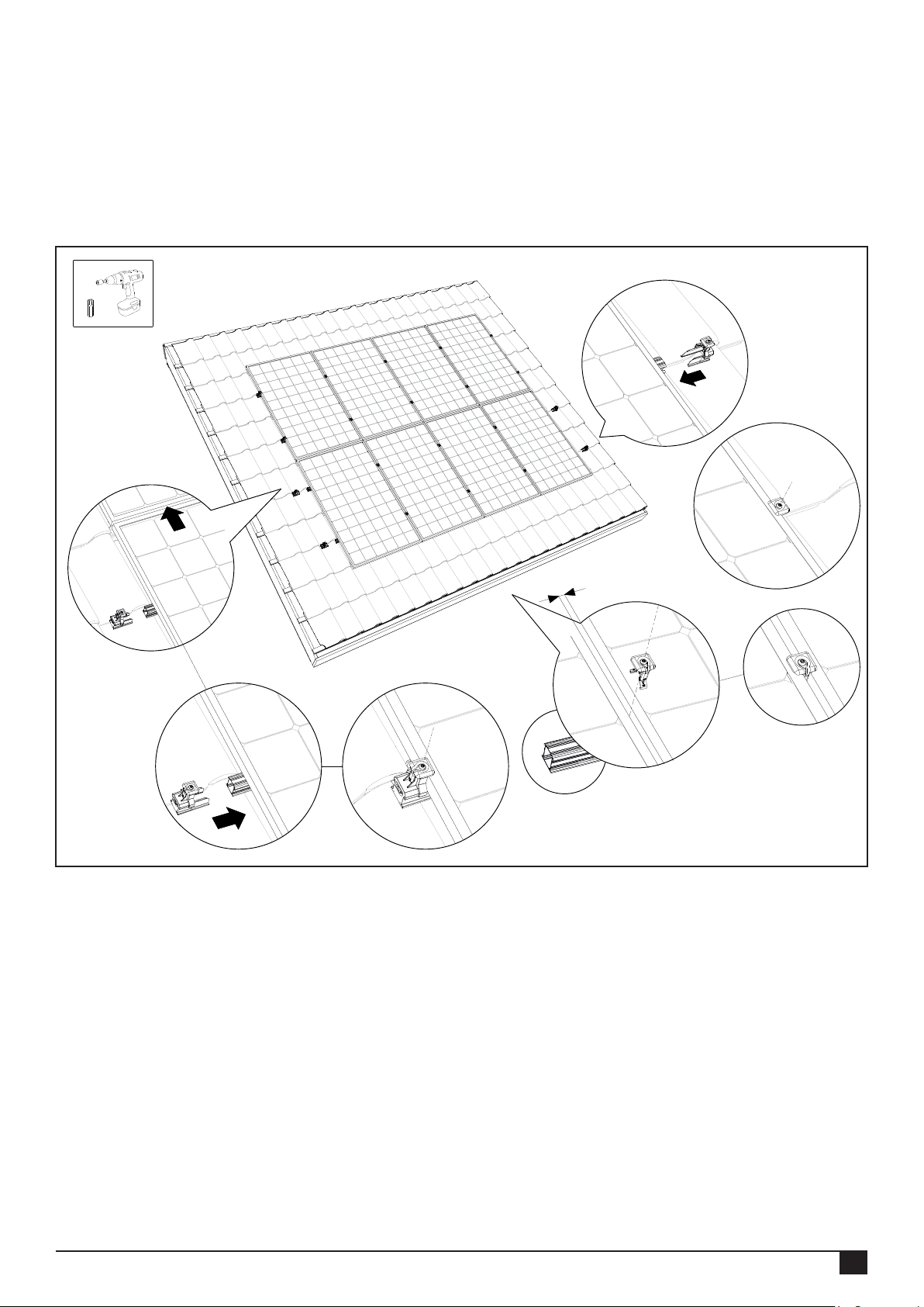
6.8 Completing the mounting of several rows under each other
1. To obtain an uninterrupted eld of panels you slide the underlying solar panels against the row of solar panels above
them.
2. Repeat the steps of chapter 6.5 - 6.7. The eld of panels is now nished!
Attention! See appendix for restrictions and other details.
T30
4
1
2
12 mm
3
Rev. 31.10.18 MANUAL FOR MOUNTING SYSTEM WITH TRUSSHOOK FOR PITCHED ROOF WITH TILES
15
Page 18
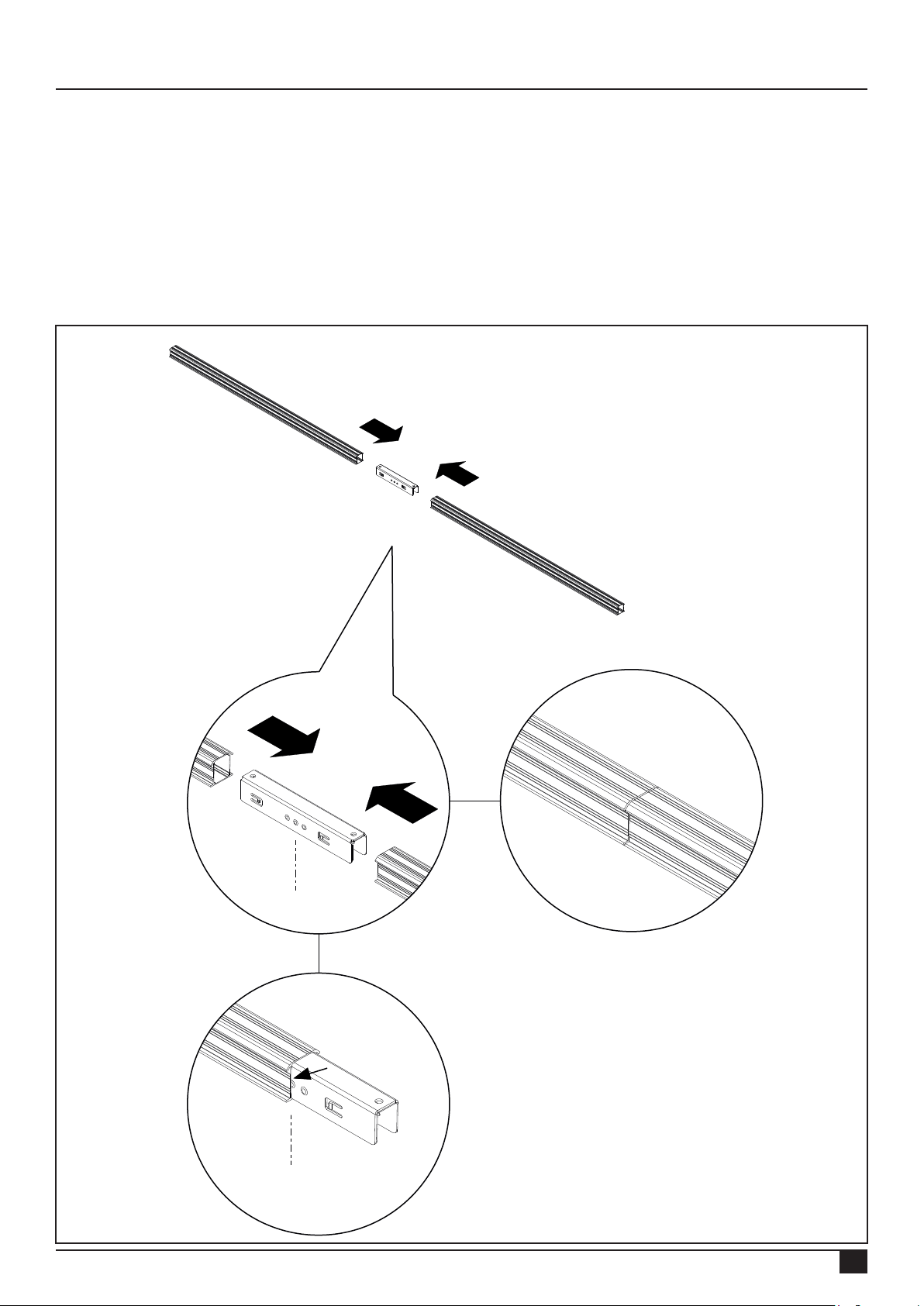
7. Installation of mounting system in landscape layout
7.1 Pre-mounting the mounting rail connector
First determine the total rail length required for the solar panels under each other.
You can connect the mounting rails to each other with mounting rail connectors. The mounting rail connector has small
clamps with teeth that grip the inside of the rail.
Slide the connector into the ends of the mounting rail. Slide the connector to the centre of the middle stud of the connector.
Connect the number of rails together until the total rail length required is reached.
Attention! See appendix for restrictions and other details.
Rev. 31.10.18 MANUAL FOR MOUNTING SYSTEM WITH TRUSSHOOK FOR PITCHED ROOF WITH TILES
16
Page 19
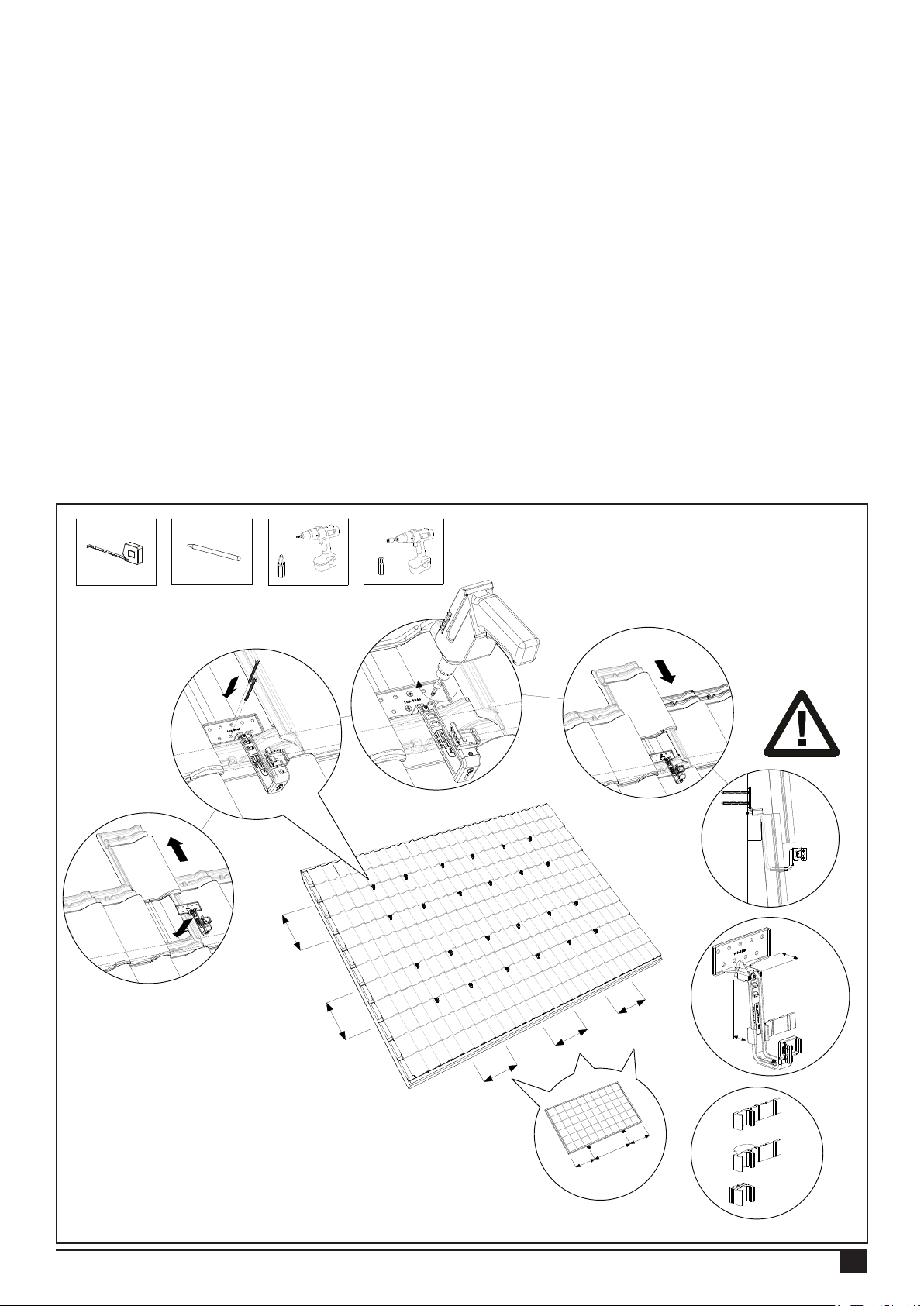
7.2 Fastening trusshooks
1. Slide the tile above the trusshook upwards, under the tile above it. Place the mounting ange of the trusshook on the roof
batten, ensure that it connects correctly and pull the trusshook against the tile. Place the trusshook in the concave section
(dip) of the underlying tile. The top adjustable part of the trusshook is a minimum of 37 mm and a maximum of 62 mm.
2. Fasten the trusshook with a minimum of 2 teller head screws 6x50/60 to the roof batten. Attention! These screws are not
supplied.
3. Tighten the torx screw at the top of the trusshook rmly with a cordless screw driver. Attention! The tightening moment of
the screw connection is 4.5 Nm.
4. Slide the tile above the trusshook down again. Some tiles must be adapted to the trusshook with an angle grinder or le
so that the tiles close correctly again. *
5. Follow the instructions of the calculator with regard to the gaps between each trusshook. They are an important guide.
The maximum lateral gap is 1.20 m. divide the number of trusshooks produced by the calculation over the possible roof
battens, with a maximum span of 1.20m. Ensure that the trusshooks are aligned with each other.
*Option: For tiles with a high water retaining edge, the lling rubber can be placed under the trusshook so that the trusshook
rests neatly on the tile. Fold the rubber to create the desired thickness. The lling steps are 5,10 and 15 mm.
Attention! Ensure that the click bracket on every trusshook is in the correct position so that the mounting rail can be
fastened to the trusshook horizontally (see chapter 5.3).
1
2
Min. 2x
30-60 cm
30-60 cm
T30
3
4,5 Nm
2/4B
4
5
37-62 mm
2/4B
2/4B
2/4B
2/4B
OPTION
1/4B
2/4B
1/4B
Rev. 31.10.18 MANUAL FOR MOUNTING SYSTEM WITH TRUSSHOOK FOR PITCHED ROOF WITH TILES
17
Page 20
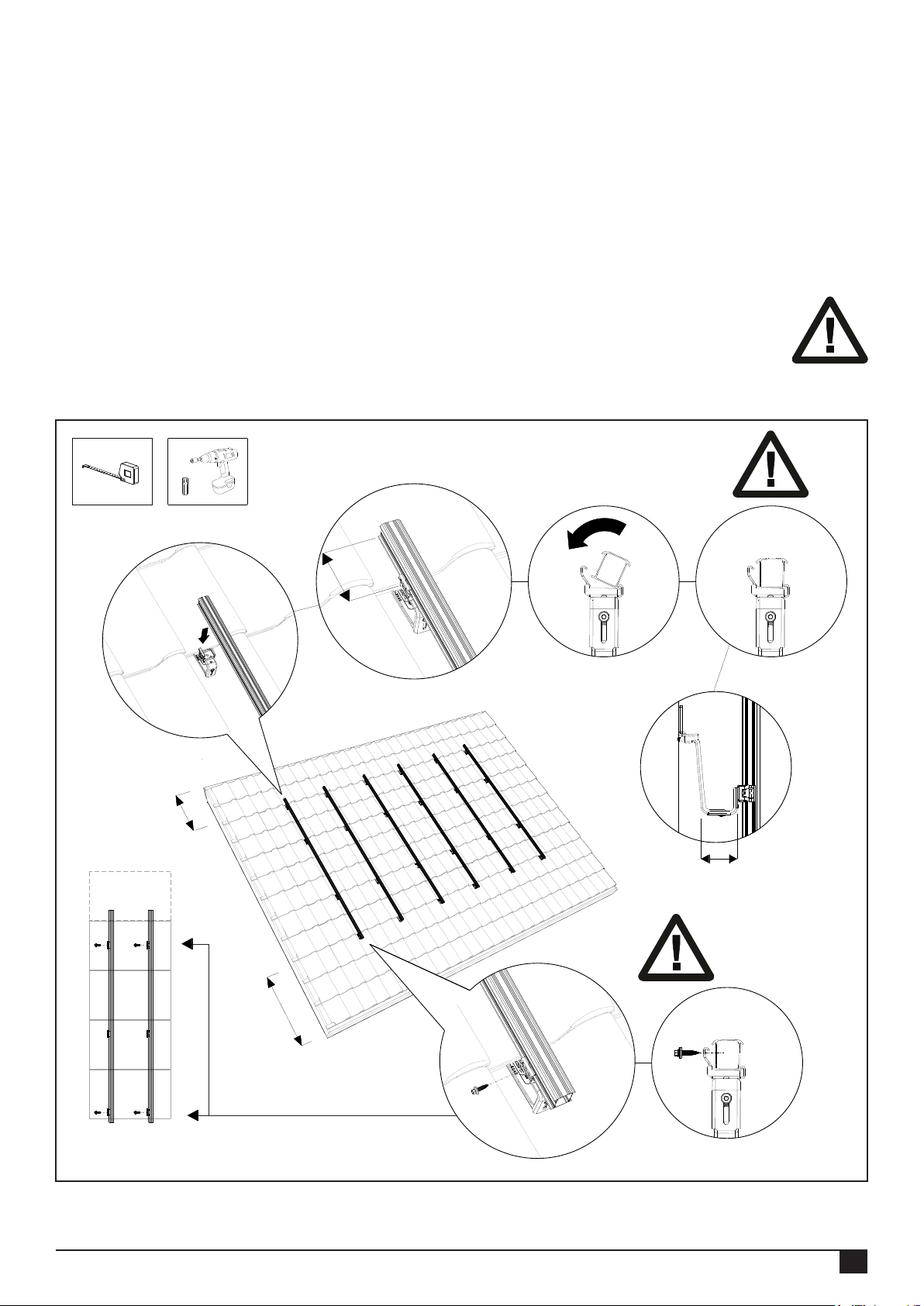
7.3 Fastening the mounting rail
1. Place the mounting rail in the installed trusshooks.
2. Ensure that the end of the mounting rails protrudes 90 - 250 mm from the last trusshook.
3. Now click the mounting rail onto the trusshooks. Ensure that it is rmly clicked into place.
4. Ensure that the mounting rail and the trusshooks are correctly aligned with each other and that the mounting rail is
positioned correctly on the trusshook. Ensure that the mounting rails are horizontally aligned with each other in connection
with the alignment of the solar panels!
The mounting rails can be aligned by means of the height adjustment on the trusshook where necessary. Unscrew the
torx screw on the underside of the trusshooks slightly. Set the desired height and retighten the torx screws. Attention! The
tightening moment of the screw connection is a minimum of 6 Nm.
5. Secure the mounting rails with a self-tapping sheet metal screw to the bottom trusshook to prevent the rails
from sliding down. Attention! Place this locking screw every three solar panels (above each other) and always
start at the bottom trusshook.
Attention! See appendix for restrictions and other details.
1
min. 30 cm
T30
2
3
Click!
min. 90 mm
4
68 -98 mm
5
min. 30 cm
Rev. 31.10.18 MANUAL FOR MOUNTING SYSTEM WITH TRUSSHOOK FOR PITCHED ROOF WITH TILES
18
Page 21
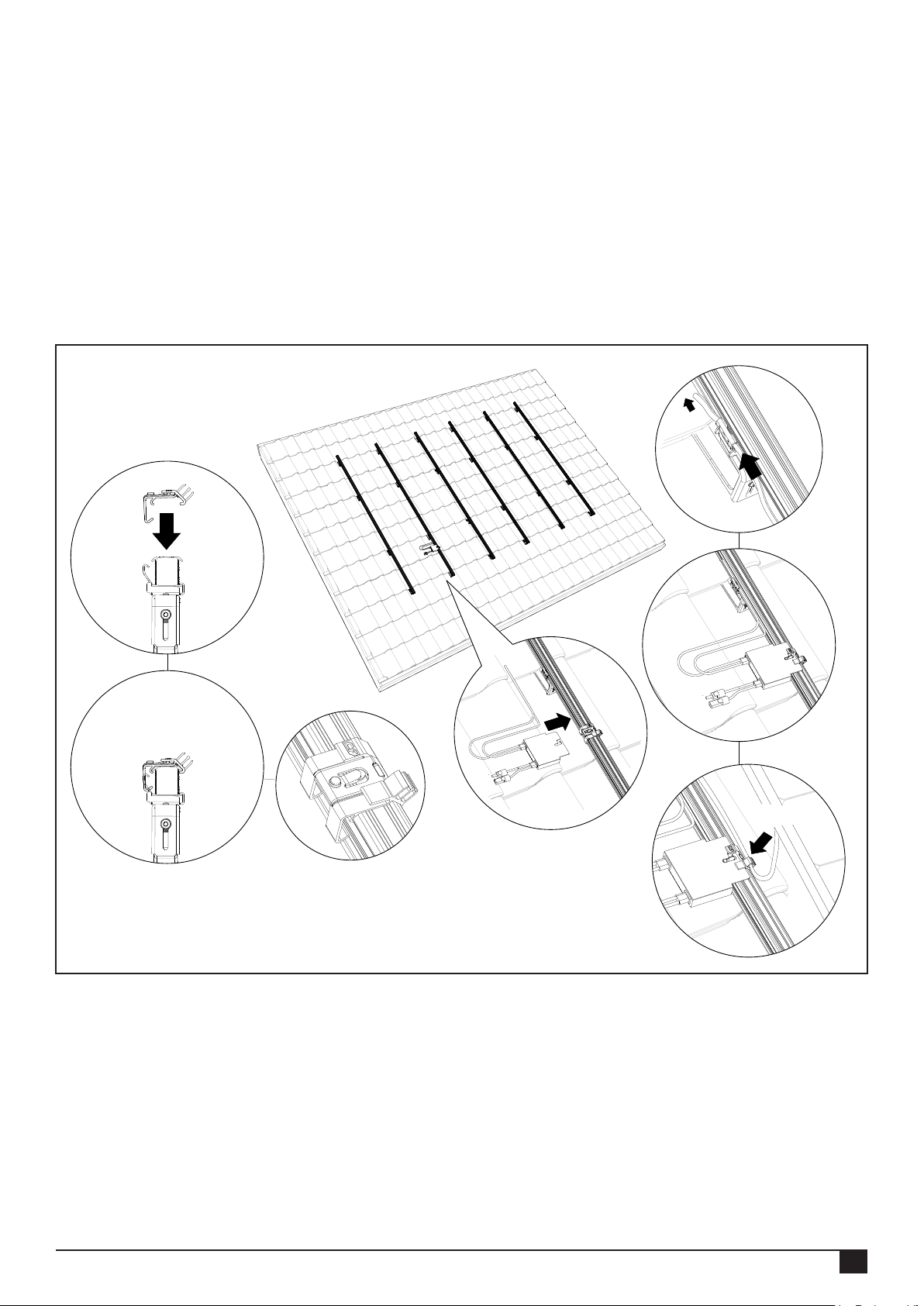
7.4 Mounting the mounting rail cable clip optimizer ready and optimizer (option)
1. Position the cable clip on the mounting rail of a row. One cable clip is used per solar panel. The cable clips are positioned
under the centre of the panel. Place the cable clips approximately 1 m apart.
2. Click the cable clip onto the mounting rails.
3. Lead the cabling through the click bracket of the trusshook and the cable clip.
Optional:
4. Click the optional optimiser onto the cable clip.
5. Lead the cables of the optimiser through the cable clip.
Attention! See appendix for restrictions and other details.
3
1
Click!
4
2
5
Click!
Rev. 31.10.18 MANUAL FOR MOUNTING SYSTEM WITH TRUSSHOOK FOR PITCHED ROOF WITH TILES
19
Page 22
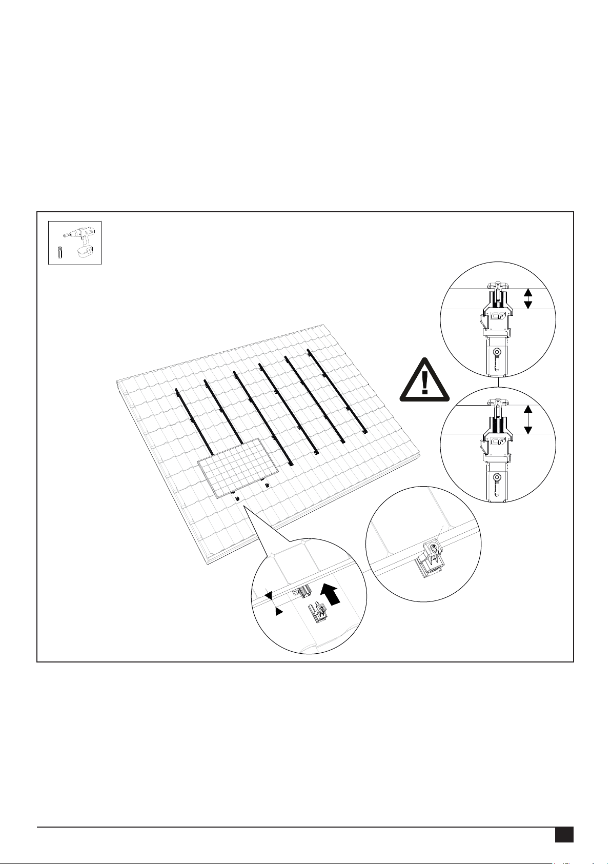
7.5 Mounting the 1st solar panel on a mounting rails
Hang the solar panel on the mounting rail. Click the cables of the solar panel into the cable clip that has been installed.
Slide the rst solar panel to the bottom of the mounting rail. Leave 20 - 35 mm of the rail protruding visibly under the solar
panel.
Now slide the mounting rail end cap with universal module (end) clip onto the mounting rail. Choose the correct recess so
that the universal module clamp connects with the solar panel. Now tighten the universal module (end) clip. Attention! The
tightening moment of the screw connection is 4.5 Nm.
Attention! The minimum panel thickness Y = 30 mm and the maximum panel thickness X = 50 mm.
Attention! See appendix for restrictions and other details.
T30
Y
1
X
2
20 - 35 mm
Rev. 31.10.18 MANUAL FOR MOUNTING SYSTEM WITH TRUSSHOOK FOR PITCHED ROOF WITH TILES
20
Page 23
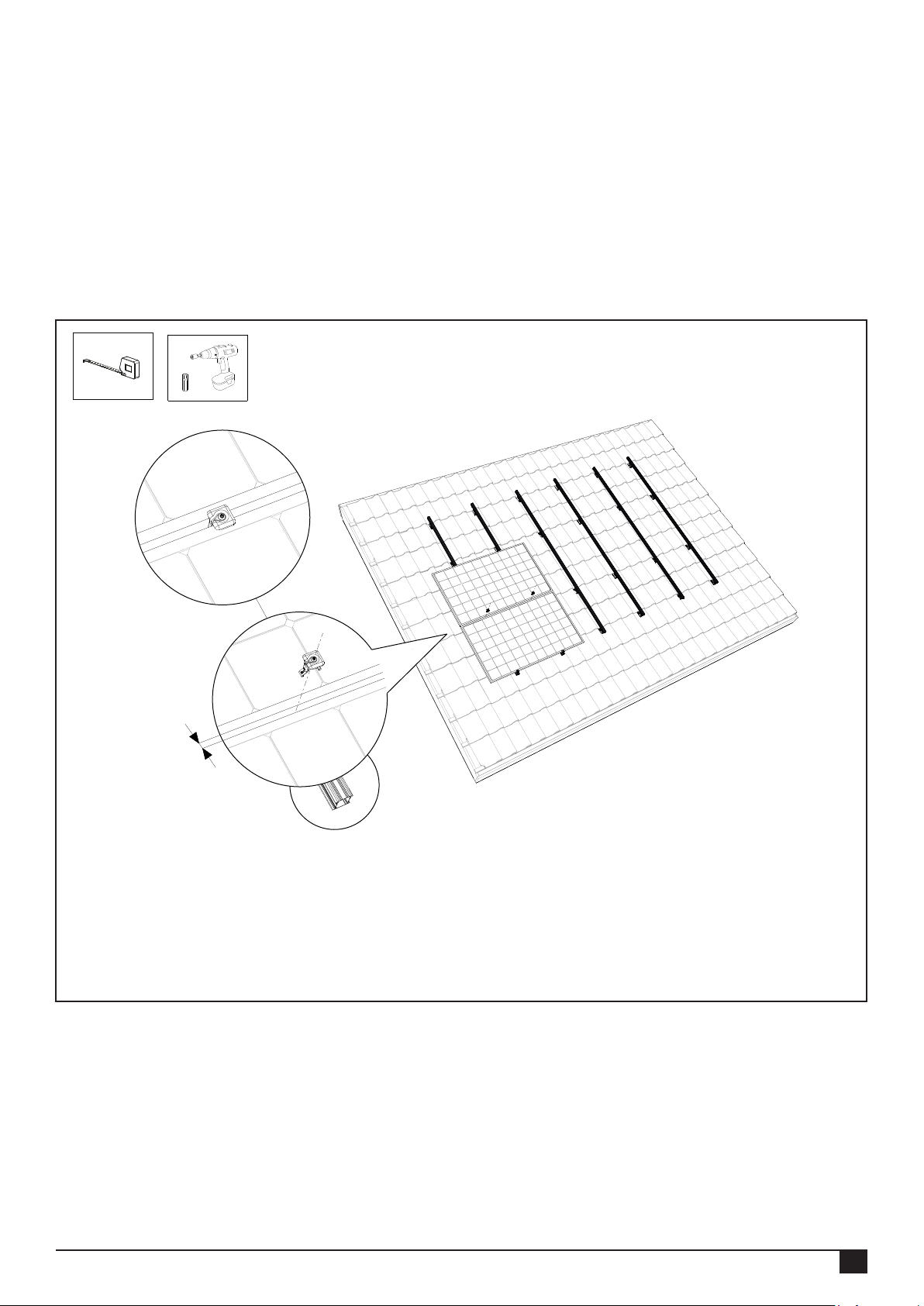
7.6 Mounting other solar panels on the rails
Click the universal module clamps onto the mounting rails. Slide them against the rst solar panel. Place the second solar
panel on the mounting rail, click the cables of the solar panel securely into the cable clip and slide the solar panel to the rst
against the universal module clamp. Now screw the universal module clamp tight.
Attention! The tightening moment of the screw connection is 4.5 Nm.
Ensure that the solar panels are lying straight before you tighten the torx screw! Repeat this with the remaining solar panels.
Attention! See appendix for restrictions and other details.
T30
12 mm
Rev. 31.10.18 MANUAL FOR MOUNTING SYSTEM WITH TRUSSHOOK FOR PITCHED ROOF WITH TILES
21
Page 24
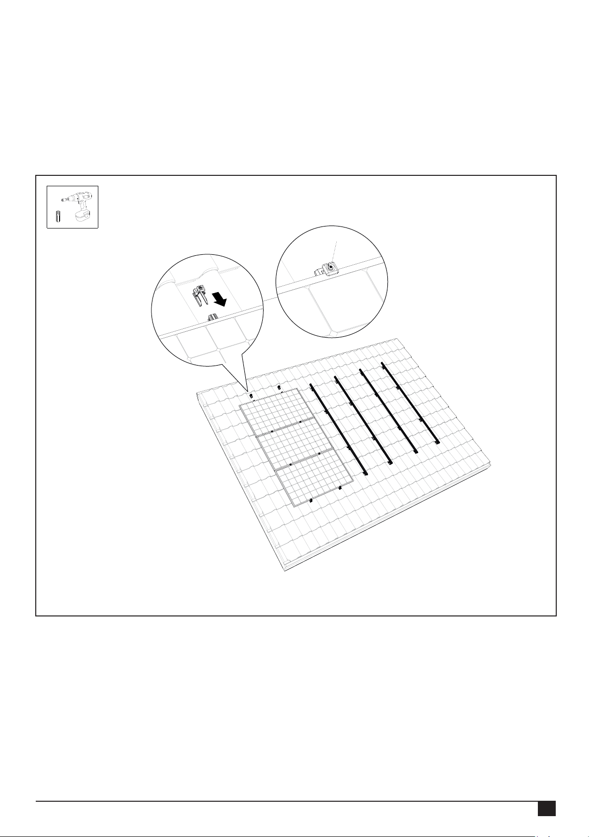
7.7 Completing the mounting of the 1st row of solar panels above each other
1. Allow the mounting rail to protrude 20 - 35 mm from the edge of the solar panel. Slide the mounting rail end cap with
universal module (end) clip onto the mounting rail. Attention! Choose the correct recess so that the end clip connects with
the solar panel.
2. Now screw the end clip rmly into position with the torx screw. Attention! The tightening moment of the screw
connection is 4.5 Nm.
Attention! See appendix for restrictions and other details.
T30
Rev. 31.10.18 MANUAL FOR MOUNTING SYSTEM WITH TRUSSHOOK FOR PITCHED ROOF WITH TILES
22
Page 25
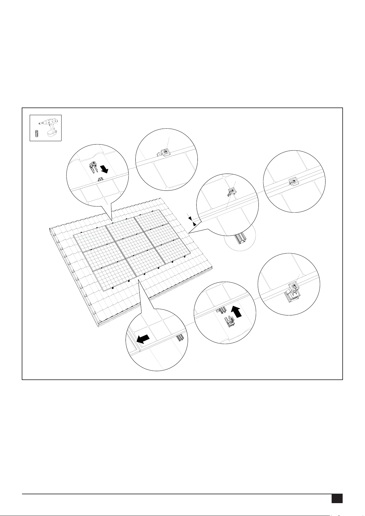
7.8 Completing the mounting of several rows next to each other
1. To obtain an uninterrupted eld of solar panels you slide the adjacent solar panels against the row of solar panels.
2. Repeat the steps of chapter 7.5 - 7.7. The panel eld is now nished!
Attention! See appendix for restrictions and other details.
T30
4
3
12 mm
1
2
Rev. 31.10.18 MANUAL FOR MOUNTING SYSTEM WITH TRUSSHOOK FOR PITCHED ROOF WITH TILES
23
Page 26
8. APPENDIX
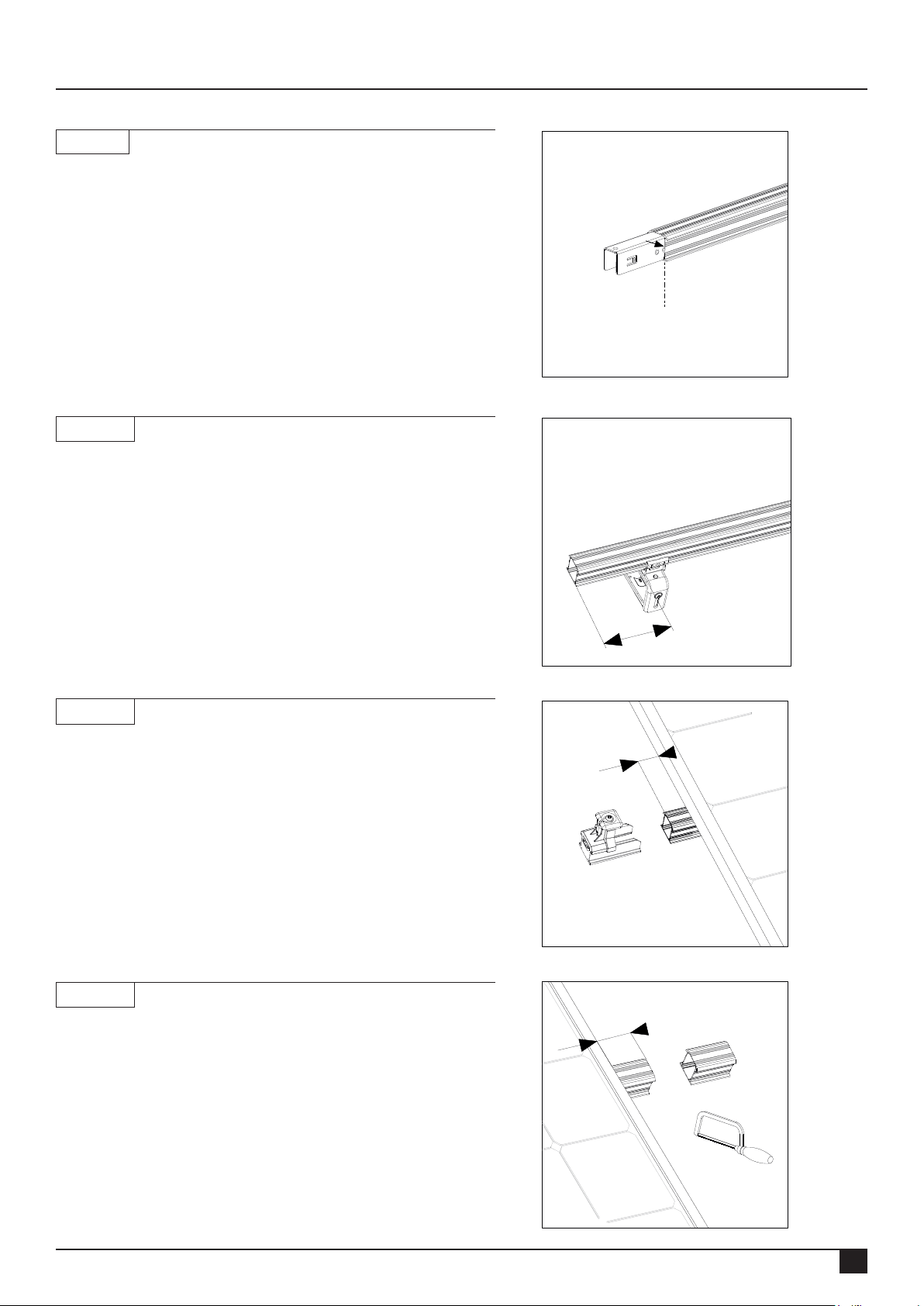
8.1 Specifications for installation
8.1 - 01
Slide the connector into the ends of the mounting rails. Slide the
connector to the centre of the middle stud of the connector.
This ensures that the connector is divided equally over the 2 rail ends.
8.1 - 02
The rst trusshook must be tted a minimum of 90 mm
from the end of the mounting rail. And a maximum of 250 mm.
8.1 - 03
The mounting rails must protrude 20 - 35 mm from the edge of the solar
panel.
8.1 - 04
The mounting rails must protrude 20 - 35 mm from the edge of the solar
panel. Saw the mounting rails to the correct length.
min. 90 mm
20 - 35 mm
20 - 35 mm
Rev. 31.10.18 MANUAL FOR MOUNTING SYSTEM WITH TRUSSHOOK FOR PITCHED ROOF WITH TILES
24
Page 27
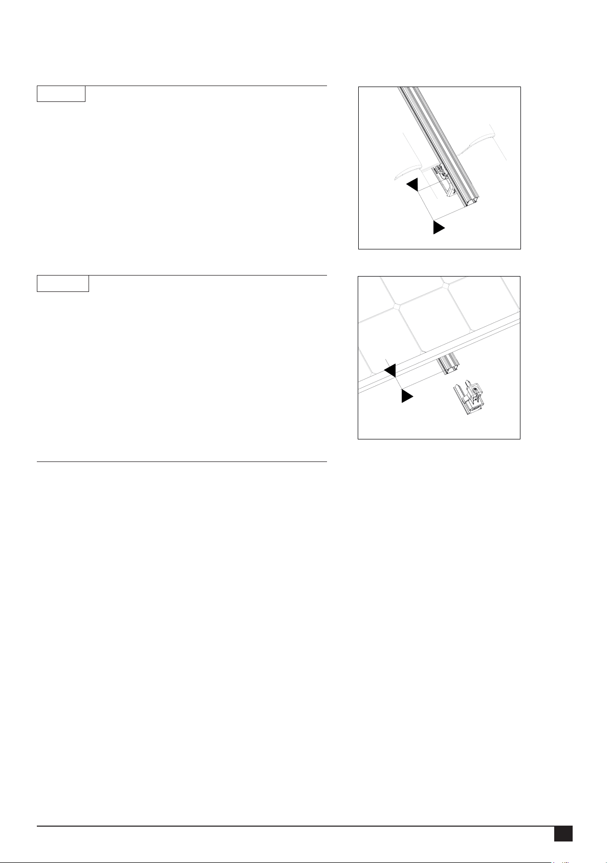
8.1 - 05
The trusshook must be mounted a minimum of 90 mm
from the end of the mounting rail. And a maximum of 250 mm.
8.1 - 06
The mounting rails must protrude 20 - 35 mm from the edge of the solar
panel.
min. 90 mm
20 - 35 mm
8.2 Tightening moments
Screws for fastening trusshooks to battens (minimum of 2 screws per trusshook):
Screws for fastening trusshooks (= screw on the top of the trusshook): 4,5 Nm
Screws for height adjustment of trusshooks (= screw on the underside of the trusshook): minimum 6,0 Nm
Screws for fastening module clamps: 4,5 Nm
Rev. 31.10.18 MANUAL FOR MOUNTING SYSTEM WITH TRUSSHOOK FOR PITCHED ROOF WITH TILES
25
 Loading...