

Page 1
TECHNICAL BULLETIN TB-20686
SPI Ground Gard 5 / 5.5
Operation, Installation, and Maintenance
S1.1 paragraph 6.1.3 Frequency of Functional Testing
“Daily (Wrist Strap) testing may be omitted if constant
monitoring is used.”
“Because wrist straps have a nite life, it is important to
develop a test frequency that will guarantee integrity of
the system. Typical test programs recommend that wrist
straps that are used daily should be tested daily.
However, if the products that are being produced are
of such value that knowledge of a continuous, reliable
ground is needed, and then continuous monitoring
should be considered or even required.” (ESD Handbook
TR 20.20 section 5.3.2.4.4)
Made in the
United States of America
SPI-20686
94391
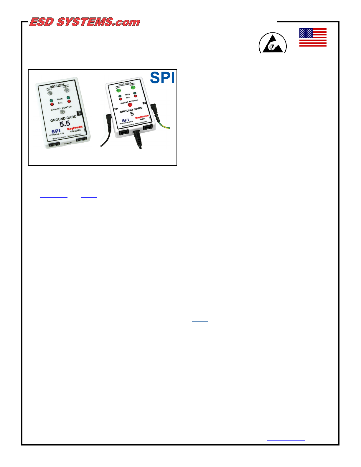
Figure 1. SPI Ground Gard items SPI-20686 and 94391.
Description
The SPI-20686 and 94391 are wrist strap and ground
monitoring devices for the electronics work station. It is
designed to constantly monitor two single wire wrist
straps using a Remote Operator Module for each user.
These units provide continuous monitoring of:
• One or two users wearing a wrist strap
• Ground (Verication between electrical and ESD
ground)
Leading companies use continuous monitors as a cost
eective component in satisfying the paragraph 6.1.3
Complicance Verication Plan requirements of ANSI/
ESD S20.20. The SPI-20686 and 94391 Continuous
Monitors provide continuous monitoring of two operators
and also functions to ensure connection to ground. If the
monitor, using capacitance technology, detects improper
grounding of the operator, the monitor will issue an
audible alarm along with an illuminated red LED to notify
the user of a problem.
Many customers are eliminating periodic testing and are
utilizing continuous monitoring to better ensure that their
products were manufactured in an ESD controlled
environment. Continuous monitoring is superior to
periodic testing. “While eective at the time of testing,
wrist strap checker use is periodic. The failure of a wrist
strap between checks may expose products to
damage from electrostatic charge. If the wrist strap
system is checked at the beginning of a shift and
subsequently fails, then an entire shift’s work could be
suspect.” (ESD TR 12-1 Section 1.0 Survey of Constant
Monitors for Wrist Straps)
Continuous Monitors eliminate the need for users to test
wrist straps and log the results; by their function, these
monitors satisfy the ISO 9000 and ANSI/ESD S20.20
Paragraph 6.2.2.2 test logging requirements. Per ESD-
The SPI-20686 and 94391 will alarm if preset values are
exceeded for capacitance, high resist and ground loss
conditions. The grounding system is redundant and will
still provide a limited grounding even if the utility ground
is lost and the system is in an alarm state.
Capacitance Type Continuous Monitors
“These types of monitors are used with a single wire
(single conductor) wrist strap. Monitors in this category
operate by “sensing” body capacitance. For capacitance monitors, an AC voltage is applied to the wrist
strap through the single conductor ground cord. Due to
capacitive coupling of the person to ground based on the
surroundings, the monitor will indicate either good or bad
depending on the manual adjustment or preset
tolerance. Since a capacitor or capacitive network
responds like a resistor to an AC current, the single
conductor wrist strap monitor only provides an estimate
of the wrist strap wearer’s apparent resistance.”
(ESD Handbook TR 20.20 section 5.3.9.2 Types of
Continuous Monitors)
Packaging
Item SPI-20686
1 Ground Gard 5.5 Monitor
2 94340 Remote Operator Modules
2 10 Foot Phone Cords
1 12 Foot Ground Cord
1 Velcro® Set
4 Screws
1 Power Adapter - 3 Prong, 12 Volts
Item 94391
1 Groud Gard 5 Monitor
2 94340 Remote Operator Modules
1 Power Adapter - 2 Prong, 12 Volts
2 Remote Operator Cables
1 Black Ground Cord
1 Green ground Cord
2 Velcro® Strips
4 Screws
1 Certicate of Calibration
ESD Systems.com • 432 Northboro Road Central • Marlboro, MA 01752 • (508) 485-7390 • Website: ESDSystems.com
ESD Systems.com • 432 Northboro Road Central • Marlboro, MA 01752 • (508) 485-7390 • Fax (508) 480-0257 • Website: ESDSystems.com
TB-5545 Page 1 of 4 Revision May 2009
TB-20686 February 2016 Page 1 of 3
© 2009 DESCO INDUSTRIES INC.
Employee Owned
© 2016 DESCO INDUSTRIES INC.
Employee Owned
Page 2
Installation
1. SPI-20686 and 94391 Monitor Head:
The SPI-20686 and 94391 Monitors are designed to
maximize valuable work area and should be mounted at
eye level above the workstation, either on a post or shelf
support. A double-sided adhesive Velcro® attachment is
provided to hold the lightweight head in place.
2. GROUND CONNECTION:
The green wire extending from the monitor must be
attached to a facility ground.
Caution: The total amount of resistance through all
monitored parts should not exceed 10.0 megohms
total.
3. REMOTE OPERATOR MODULES:
The remote operator modules can be
mounted at the front of the work
surface, usually under the tabletop and
ush with the front edge. Two screws
for each unit are provided for mounting.
Connect each remote to the monitor unit using the
telephone cable with RJ11 connectors.
Calibration Procedure Using 94373
Tester
Testing the Remote Modules
Refer to Figure 2 to see the connection setup for the
94373 tester to the SPI-20686 and Figure 3 for the
94391 monitor. Make sure that the switch located on the
face of the tester is toggled to LEFT WS / RIGHT WS. If
connected properly, all three LEDs on the monitor should
be illuminated green.
SPI-20686
Remote
Remote
4. POWER UP TEST
After installing the Monitor , remote units, and making the
necessary connections without the wrist straps
connected, the unit should POWER UP with the wrist
strap LED’s OFF and the audible alarm SILENT. If you
have no response to power or a red LED, check AC
outlet for proper ground or refer to trouble shooting
section.
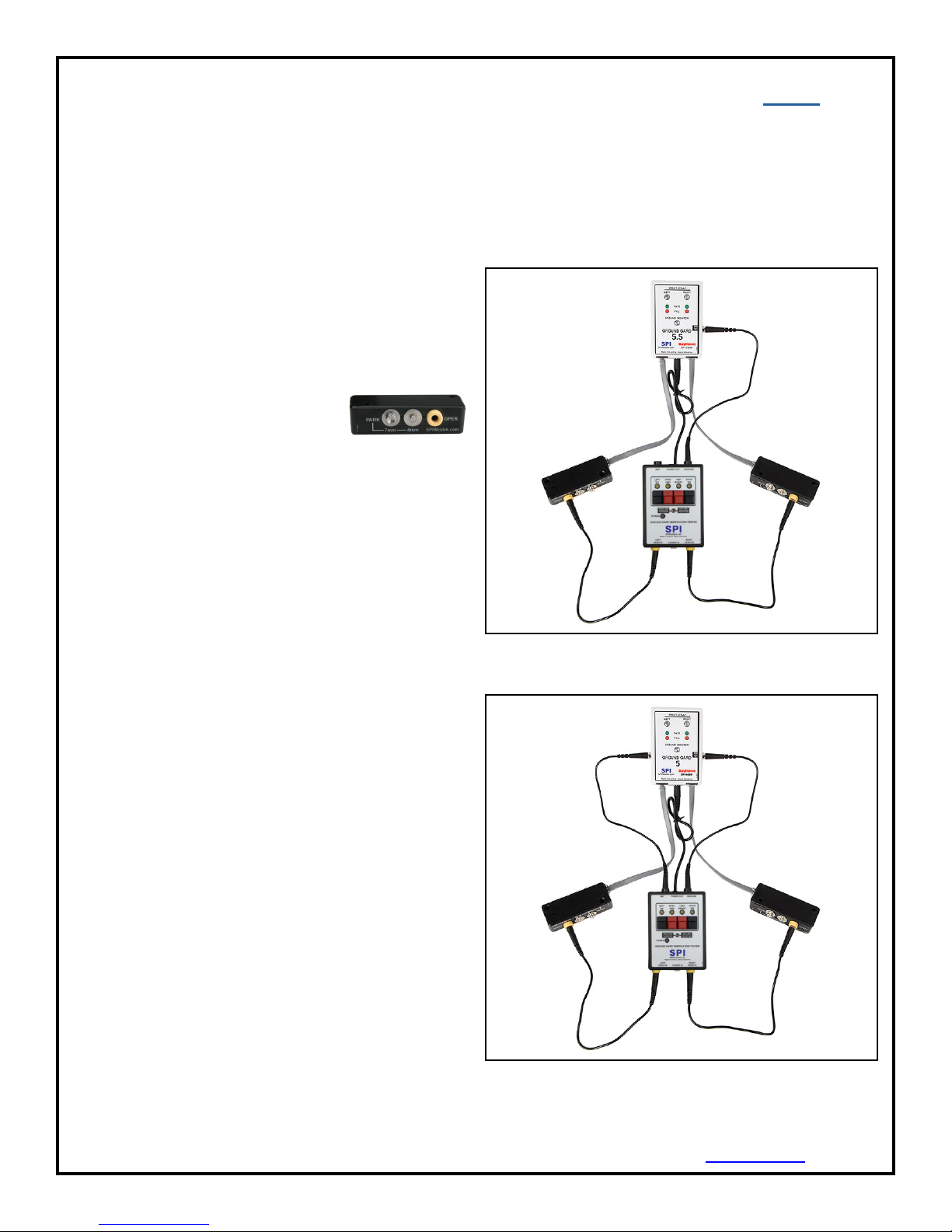
PARK SNAP
The audible alarm is designed to alert both operator and
supervisor. The Park Snap feature provides a means
for an operator to disconnect when normally leaving the
work area, without the audible alarm sounding, and it
provides a means of wrist cord storage. You may also
disconnect the coil cord by unplugging the banana plug
from the Remote Module. Both a 7mm and 4mm Park
Snap is provided on each module.
Remote Module Description
Inside both remote modules are infrared sensors that
react to the insertion of a wrist strap wire with a banana
plug. When the banana plug is inserted, the base unit is
activated for that remote module. The Monitor LED for
the left or right wrist strap will light showing the condition
of that strap. If correct, the LED should be GREEN.
94373
Figure 2. Connecting the SPI-20686 to the 94373 Tester.
94391
Remote
94373
Remote
Should the wrist strap fail, be worn incorrectly or
removed by the operator, the red indicator will ash,
calling attention to a problem. Should the ground
connection be lost, the red light and alarm will be
activated. The monitors are continuous and even a
momentary break will cause alarms. The remote
modules are set at the factory to allow for sensitivity of
the “average” human body model.
ESD Systems.com • 432 Northboro Road Central • Marlboro, MA 01752 • (508) 485-7390 • Website: ESDSystems.com
ESD Systems.com • 432 Northboro Road Central • Marlboro, MA 01752 • (508) 485-7390 • Fax (508) 480-0257 • Website: ESDSystems.com
TB-5545 Page 2 of 4 Revision May 2009
TB-20686 Page 2 of 3
© 2009 DESCO INDUSTRIES INC.
Employee Owned
Figure 3. Connecting the 94391 to the 94373 Tester.
© 2016 DESCO INDUSTRIES INC.
Employee Owned
Page 3

To test the resistance of the left remote module, press
the black button labeled LEFT WS on the tester. If the
remote module is properly calibrated, the monitor’s
audible alarm will sound and the LEFT WRIST STRAP
LED will illuminate red. If the LED remains green, locate
the trim pot underneath the respective remote module.
Hold down the tester’s LEFT WS button and carefully
adjust the trim pot in a counter-clockwise direction until
the monitor indicates a FAIL condition. If properly
calibrated, the monitor should now indicate a FAIL
condition when the tester’s LEFT WS button is pressed.
To test the resistance of the right remote module, press
the black button labeled RIGHT WS on the tester. If
the remote module is properly calibrated, the monitor’s
audible alarm will sound and the RIGHT WRIST STRAP
LED will illuminate red. If the LED remains green, locate
the trim pot underneath the respective remote module.
Hold down the tester’s RIGHT WS button and carefully
adjust the trim pot in a counterclockwise direction until
the monitor indicates a FAIL condition. If properly cali-
brated, the monitor should now indicate a FAIL condition
when the tester’s RIGHT WS button is pressed.
Testing the Ground Monitor
Refer to Figure 2 to see the connection setup for the
94373 to the SPI-20686 and Figure 3 for the 94391.
Make sure that the switch located on the face of the
tester is toggled to LEFT WS / RIGHT WS. If connected
properly, all three LEDs on the SPI-20686 and 94391
should be illuminated green.
Disconnect the cords from the banana jacks on both
remote modules. Next, toggle the switch located on the
face of the tester to OPEN GND / HI RESIST. Press the
red button labeled OPEN GND on the tester, and if the
monitor is functioning properly, its audible alarm should
sound and the GROUND MONITOR LED should
illuminate red.
Press the red button labeled HI RESIST on the tester,
and the monitor’s audible alarm should sound and the
GROUND MONITOR LED should illuminate amber.
If any of these conditions are not met, contact the
manufacturer for repair.
With the system set up and operating, and the operator’s
wrist strap connected to the remote module:
Turn the trim pot clockwise until the LED illuminates
green. Disconnect the wrist cord from the band. An
audible alarm will sound and the LED will illuminate red.
If not, carefully turn the trim pot counter-clockwise until
the LED illuminates red. Reconnect the cord to the wrist
band. The alarm should cease and the LED should
illuminate green.
Ground Monitor
The SPI-20686 and 94391 include a ground monitoring
system that assures a positive ground connection for the
workstation. The resistance range is preset at the factory
to monitor that the connection to ground is within the
resistance range of 0.01 to 10 megohms. A visual and/or
audio alarm will verify pass or fault conditions.
CONDITION INDICATOR
PASS - Properly Grounded - LED Green
with Resistance less - No Audible Alarm
than 10 Meg.
HI RESIST - Grounded, but - LED Oscillate Green to
Resistance exceeds 10 Meg. Amber or Flashing Red
- Audible Alarm
FAIL - Loss of 1 or both - LED Flashing Red
redundant grounds, failure - Audible Alarm
of monitor, worktop, mat, etc.
Safety Issues
With regards to the safety issue, it is hard to conceive of
a safer situation than exists with the Ground Gard 5.5 as
designed.
1. The SPI-20686 and 94391 have a built-in safety
resistance of no less than 500k ohms at each remote
unit.
2. The transformer is wound on a split bobbin with 1500
volt insulation to assure no possible line leakage.
3. The circuits are double insulated by virtue of the
insulated plastic boxes.
4. 500k ohms internal to the SPI-20686 and 94391 and
one megohm in the wrist strap isolate the operator.
Installation Adjustments
Should your system alarm without obvious cause, rst
troubleshoot and verify all connections. If all the
connectionsare correct, the base unit should be adjusted
to compensate for a dierent HBM (human body model).
We preset the units at the factory at 100pF and your
operator might be out of the tolerance range caused
either by body chemistry, bulk capacitance or impedance
dierences.
Follow these steps to adjust and personalize the base
unit:
Locate the small hole underneath the desired remote
module. Inside this hole is a trim pot device that is
adjustable by using a small at-head screwdriver.
ESD Systems.com • 432 Northboro Road Central • Marlboro, MA 01752 • (508) 485-7390 • Website: ESDSystems.com
ESD Systems.com • 432 Northboro Road Central • Marlboro, MA 01752 • (508) 485-7390 • Fax (508) 480-0257 • Website: ESDSystems.com
TB-5545 Page 3 of 4 Revision May 2009
TB-20686 Page 3 of 3
© 2009 DESCO INDUSTRIES INC.
Employee Owned
This may be varied by using a miltimeter set on ohms.
Connect the telephone type wire to the monitor and to
the remote unit. Place one end of the probe into the
banana receptacle at the remote, and the other to the
collar (power supply jack) located at the monitor.
Limited Warranty, Warranty Exclusions, Limit of
Liability and RMA Request Instructions
See ESDSystem.com’s Terms and Conditions -
http://esdsystems.descoindustries.com/TermsAndConditions.aspx
© 2016 DESCO INDUSTRIES INC.
Employee Owned
 Loading...