

Page 1

QUICK 713
LEAD FREE REWORK SYSTEM
Instruction Manual
Thank you for purchasing this unit. It is designed for lead free soldering & de-soldering. Please
read this manual before operating the unit. Store this manual in a safe, easily accessible place
for future reference.
Page 2

1
TABLE CONTENT
1. Summary…………………………………………………………………………………………...2
2. Safety Instruction………………………………………………………………………………....2
3. Specification and Characteristic…………………………………………………………………3
3.1 Soldering Iron Part …………………………………………………………………………...3
3.2 De-soldering Tool Part ………………………………………………………………………...3
3.3 SMD Rework Part …………………………………………………………………………...3
4. Prepare and Connection …………………………………………………………………………...4
4.1 Connection of the Soldering Iron Part……………………………………………………… 4
4.2 Connection of the De-soldering Tool Gun……………………………………………………5
4.3 Connection of the SMD Rework Part…………………………………………………………6
4.4 Connection of the Main Unit…………………………………………………………………6
5. Parameter Setting………………………………………………………………………….………6
5.1 Menu and Parameter Setting..…………………………………………………………………6
5.2 T emperature and Airflow Setting………………………………………………………………7
5.3 Sleep Time Setting and Resume………………………………………………………………8
6. Operation.………………………………………………………………………….……………9
6.1 Select the Tool………………………………………………………………………………....9
6.2 Operation of the Soldering Iron …………………………………………………………….10
6.3 Operation of the De-soldering Gun.……………………………………………………..11
6.4 Operation of the SMD Rework System …………………………………………………...13
6.5 On Line with the Hot Plate…………………………………………………………………14
7. Temperature Calibration………………………………………………………………………….14
8. Error Messages.…………………………………………………………………………………..15
9. Care and Maintenance…………………………………………………………………………...15
9.1 Maintenance of the Soldering Iron ………………………………………………………….15
9.2 Maintenance and servicing of the De-soldering Gun……………………………………….18
9.3 Parts Assemble and Disassemble of the SMD Rework …………………………………… 23
9.4 Replace the Fuse………………………………………………………………...…………..23
10. Tips………………………………………………………………………………………...…..24
Page 3

2
Ⅰ. Summary
Thank you for purchasing the unit which including the soldering iron part, de-soldering gun part
and SMD rework part. It is a good assistant. The three tools can work at the same time.
Ⅱ. Safety Instruction
z Please use the unit only as the described manner , and a voi d abusing it.
z The unit shall only be used with rated voltage and frequency. (Refer to the trademark back of the equipment.)
z The unit is equipped with a 3-wires grounding plug and must be plugged into a 3-terminal grounded socket.
Do not modify plug or use an ungrounded power socket. If an extension cord is necessary, use only a 3-wire
extended grounding cord.
z When the power is on, do not touch the metal part because the temperature of the tip, or the nozzle, or the
sucking nozzle will be up to very high, which may be hurt you.
z Do not wet the soldering station. Don’t use or disconnect it with wet hands, and without to force the supply
cord.
z Advise other people in the working area to turn the power off when in a break or after using the unit because
the unit can reach a very high temperature and may cause potentially dangerous.
z No replace any parts or install the tips before turning the power off and cooling down the searing-iron to room
temperature.
z Do not use the unit near the flammable items.
z The soldering process will produce smoke, so make sure the area is well ventilated.
z A periodically maintenance (description see in this manual) of the unit is necessary. Do not use the unit if it is
damaged, especially the power supply cord and the case.
z Do not modify the unit by oneself.
z Replace only with genuine parts.
z Children do not recognize the risks of the electrical appliance. Therefore use and keep the unit out of the
reach from children.
TOOL1 KEY
AIR
KEY
TEMP
KEY
VACUUM KEY
INFO
KEY
SOCKET OF
SOLDERING
POWER
SWITCH
TOOL2 KEY
TOOL3
KEY
SOCKET OF
DESOLDERING
TOOL
FIKTER SOCKET of
DESOLDERING TOOL
HANDLE OF SMD
REWORK
Page 4

3
Ⅲ. Specification and Characteristic
3.1 Soldering Iron Part
3.1.1 Specification of the Soldering Part
Power 60W
The temperature range of the iron 200℃~480℃
The time range of the sleeping 0~99 (unit: minute)
Temperature Stability ±2℃ (Without air flow and no load)
Highest Ambient Temperature 40℃
Tip to Ground Resistance <2Ω
Tip to Ground Potential <2mV
Heating Element Electromagnetic heater
3.1.2 Characteristic of the Soldering Part
1. Recovery of the temperature and calefactive is rapid and exactly. Display the temperature with the large LCD
by microcomputer and Control the temperature by PID. Especially it is suitable to the lead free soldering.
2. Lock the calibration and the parameter setting with the password.
3. Digital adjustment of the temperature and with functions of sleeping or shut off one tools.
4. Digital calibration and operate conveniently and easy.
5. Various types of tips are available and replace tips conveniently.
6. The soldering handle is light and use is comfortable.
3.2 De-soldering Tool Part
3.2.1 Specification of the De-soldering Tool
Power of the pump 12V/2A
Power of heating 90W
Temperature of nozzle 200℃~480℃ (See the working mode table)
Pump Diaphragm pump
Vacuum suction 600mmHG
Nozzle to ground resistance Less than 2Ω
Nozzle to ground potential Less than 2mV
The time range of the sleeping 0~99 (unit: minute)
3.2.2 Characteristic of the De-soldering Tool
1. Powerful built-in vacuum pump, without connecting the outer vacuum system.
2. Sensor closed-loop temperature control for heating system, precise temperature.
3. Heater which is 36V powered is fully isolated form mains. Safe and reliable.
4. Key type adjusting parameters and with auto sleeping function.
5. Temperature calibrate digitally.
6. Suction nozzle and heater are specially designed so that even the melting solder can be absorbed into the filter
Page 5

4
without frequent maintenance. High efficiency.
7. Heat resistant vacuum hose used prevents it from being burned by touchi ng th e heat ing parts.
3.3 SMD Rework part
3.3.1 Specification of the SMD Rework system
3.2.2 Characteristic of the De-soldering Tool
1. There is lock-function and the parameter setting with password protection.
2. Real-time operation and automatically sleeping function when putting the handle on the holder.
3. Closed loop sensor, temperature can be controlled by zero voltage triggering mode. Large power and rapid
heating. Temperature can be conveniently adjusted and the temperature is accurate and stable, and not affected
by airflow.
4. It is with a brushless whirlpool motor and the airflow is adjustable with a wide range but no level. It is a
multipurpose unit.
5. Automatic cooling system can prolong the heating element’s life and protect the handle.
3.2.3 Usage
1. It is suitable to the de-soldering of the SMD components, such as SOIC, CHIP, QFP, PLCC, BGA and so on.
2. It is suitable to hot shrink, drying, remove lacquer and mucosity, thaw, preheating, disinfect and so on.
3. It is suitable for the situation needing different range airflow, softer or heavier.
Ⅳ. Prepare and Connection
Note: Check the parts in the package as the packing list. Some option parts may be not in the
package if do not order.
4.1 Connection of the Soldering Iron Part
1. Iron Holder and Sponge
(1) Dampen the small cleaning sponge with water and then squeeze it dry. Place it in the groove of the iron
holder base.
(2) Add a little water to the iron holder. The small sponge will absorb the water to keep the large sponge
above it wet all times. It may only use big sponge and not use small one.
(3) Dampen the larger cleaning sponge and place it on the iron holder bas e.
(4) During the operation, it also can clean the tip with the cleaning ball which is made of soft brass wires.
CAUTION: If the sponge becomes dry during working, add appropriate water.
Power 1000W
Temperature range 100℃~500℃
Airflow range 1~120
Maximal airflow 120 L/min
Page 6

5
2. Connection
(1) Connect the connector plug of the iron handle cord to the socket “TOOL1” in front of the soldering
station. Take notice of the inserting position of connector plug.
(2) Place the soldering iron in the iron holder.
Turn clockwise firmly
Align the grooves and pins and
push stranght in
4.2 Connection of the De-soldering Tool Gun
4.2.1 Names of De-soldering Gun
Nozzle: Transmits heat for melting solder. It is entrance of the melted solder. Expendable part.
Filter Pipe: Inside it, there is the ceramic paper filter (s) and spring filter pipe of the melted solder and flux.
Spring filter pipe is expendable part.
Back Holder Assembly: Secures the filter pipe.
Release Knob: Push down to remove the filter pipe.
Indicator: Indicate when nozzle and heating element need cleaning and when filters need replacing.
Hose: Connects to the outside filter.
Trigger: Squeeze to start absorption. Do not pull the trigger before fully heating the nozzle.
Heating Element: Require clean of its Inside.
Cord Assembly: Connects to the receptacle
4.2.2 Use of the Sponge and the Gun’s Holder
1. Take out the de-soldering gun and put it in gun’s holder.
2. Dampen the cleaning sponge with water and then squeeze it dry. Be sure to remove the round portion of the
sponge and place it in the holder.
3. Connect the metal plug of cord assembly to the receptacle (marked“TOOL2”) .
Nozzle
Filter pipe
Back Holder Assembly
Release Knob
Indicato
Heating Element
Trigger
Hose
Cord Assembly
Page 7

6
4. Connect the external filter to the tie-in’s hose on the unit, in accordance with the mark on the extern al filter,
need to insert fully, and connect the other side of filter to de-soldering gun’s hose.
Note: The external filter has connection orientation, and it muse be connected according to the
mark, otherwise affect suction.
4.3 Connection of the SMD Rework Part
Select suitable nozzle to install. After that, put the re-soldering hand le on the holder.
4.4 Connection of the Main Unit
1. Insert the power plug into the grounding power socket.
2. Connect one end of grounding cord to the grounding hole of the soldering station and the other to ground.
3. Switch on the power supply.
Ⅴ.Parameter Setting
5.1 Menu and Parameter Setting
5.1.1 Enter into the Menu
1. Turn off the power switch.
2. Press and hold the “INFO” and “VACUUM” keys simultaneously and not loosen, an d then turn on the power
switch. At the time, the LCD shows
. After that, the LCD shows (as followings).
Which means it has come into the password inputting interface of the menu setting. Only when the inputting
password is right, it can enter into the menu setting.
3. Input password: Click the “TEMP▲”or“TEMPd”key to input 100’s digit. And then click the “VACCUM”
key when the selected value of the 100’s digit displaying and then into the 10’s digit set. The setting methods
of the 10’s digit and 1’s digit are same with the 100’s digit.
4. There are two times to input the password. If the inpu tting password is not right at the first t ime, the process
returns the password-inputting window at once. If the password inputting is error two times continues, it
comes into the work state and the displaying will shows “
“, at the time, temperature and airflow cannot be
set.
5. If the password is right, the displaying window will display “
”, and then click “VA CUUM” key in to the
menu setting state. The window shows “set”, at the time, it can change the parameters of the menu.
Connect to main unit
Fully insert filter into the
Filter is expendable.
Connect to gun
Airflow direction
Page 8

7
5.1.2 Menu and Parameters Setting
1. There are three submenus: “-1-”,“-2-”,“-3-”. Click “TEMP▲” or “TEMP▼” key can select the submenu.
After selecting, click “VACUUM” key into the parameter setting of the submenu.
2. Submenu “-1-” means: when click the “VACUUM” key, it can exit from the menu setting and enter into the work
state.
3. Submenu “-2-” means sound setting (refer to the 5.1.3 sound setting).
4. Submenu “-3-” means password setting. The LCD displays “
” after into the submenu “-3-” (refer to
the 5.1.4 password setting).
5. After setting the parameters in the submenu “-2-” or “-3-”, click “VACUUM” key” to the “-1-”.
5.1.3 Sound Setting
1. Click “TEMP▲” or “TEMP▼” key to select “-2-”in the menu setting and then click “VACUUM” key enter
into the sound setting. The LCD shows “SP”.
2. Click “TEMP▲” or “TEMP▼” key to select sound mark “
”. If “ ” mark displaying, it means the unit has
sound hinting. If not “ ” mark displaying, it means without sound.
3. After setting, click “VACUUM” key to return submenu“-1-”.
5.1.4 Password Setting
1. Click “TEMP▲” or “TEMP▼” key to select “-3-”in the menu setting and then click “VACUUM” key enter
into the password setting. The LCD shows “
” and the 100’s flicking.
2. Click “TEMP▲” or “TEMP▼” key to change the hundred digital and then click “VACUUM” key to ten
digital set. Ten digital and one digital setting method is the same as the hundred digital setting. After finishing
the first time password inputting, click “VACUUM” key to the secondary password input.
3. If the password is not the same as last time, click “VACUUM” key to return submenu“-1-”.
4. If the password is the same as the last time, the changed password is successful. The new password is stored
into the unit. Click “VACUUM” key and the LCD shows “OK” and then return submenu“-1-”.
5.2 Temperature and Airflow Setting
Click “TOOL1”, “TOOL2”, “TOOL3” key into the single displaying window, and then click “TEMP▲” or
“TEMP▲” key or “AIR▲” key or “AIR▼” key to change the temperature or the airflow.
CAUTION:
z Make sure the temperature of the station can be adjusted (the password is right or the password is initial
“000”).
z Only when the tool is in the single displaying state, it can set the temperature and the airflow.
z If the power supply is cut off when setting, the setting data will not be stored.
5.2.1 Temperature Setting
Raise temperature: Click “TEMP ▲” key and then the temperature will rise1℃, and the LCD displays the
Page 9

8
current setting temperature. If pressing “TEMP ▲”not loosely at least one second, the
setting temperature will rise rapidly. Loose the “TEMP ▲” key until up to the needed
temperature.
Reduce temperature: Click “TEMP ▼” key and then the temperature will drop 1℃, and the LCD displays the
current setting temperature. If pressing “TEMP ▼” key not loosely at least one second, the
setting temperature will drop rapidly. Loose the “TEMP ▼” key until down to the needed
temperature.
5.2.2 Airflow Setting
Raise Airflow: Click “AIR ▲” key and then the airflow grade will rise 1, and the LCD displays the current
setting airflow grade. If pressing “AIR ▲”not loosely at least one second, the setting airflow
grade will rise rapidly. Loose the “AIR ▲”key until up to the needed airflow grade.
Reduce Airflow: Click “AIR ▼” key and then the airflow grade will drop 1, and the LCD displays the current
setting airflow grade. If pressing “AIR ▼”not loosely at least one second, the setting airflow
grade will drop rapidly. Loose the “AIR ▼”key until down to the needed airflow grade.
5.3 Sleep Time Setting and Resume
5.3.1 Sleep Time Setting
1. Sleep time setting of the soldering iron: click “TOOL1”key into the single displaying window of the
soldering iron. And then pressing the “INFO” key and not loosen, at the time, click “TEMP▲” or “TEMP▼”
key to change the sleeping time.
The sleeping time range of the soldering iron is from 0 to 99minutes.
2. Sleep time setting of the re-soldering gun: click “TOOL2”key into the single displaying window of
the re-soldering gun. And then pressing the “INFO” key and not loosen, at the time, click “TEMP▲” or
“TEMP▼” key to change the sleeping time.
The sleeping time range of the re-soldering gun is from 0 to 99minutes.
3. Sleep time setting of the SMD Rework Tool: click “TOOL3” key into the single displaying window of the
SMD rework tool. And then pressing the “INFO” key and not loosen, at the time, click “TEMP▲” or “TEMP
▼” key to change the sleeping time.
The sleeping time range of the SMD rework tool is from 0 to 999seconds.
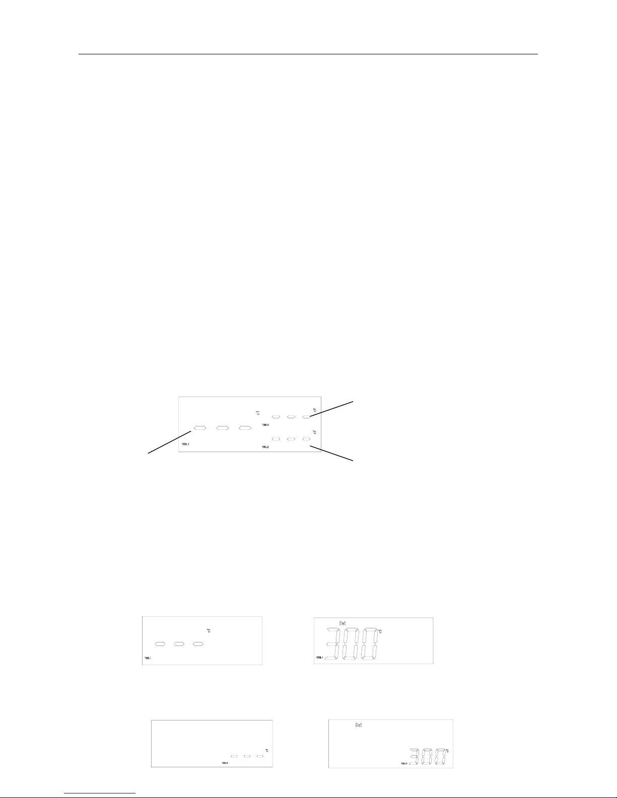
Sleeping time interface of the soldering iron
Sleeping time interface of the re-soldering gun
Sleeping time interface of the SMD rework tool
Page 10
9
5.3.2 Resume from the Sleep
1. Resume of the soldering iron:
1) Click “TOOL1” key.
2) Take up the soldering iron handle from the holder.
2. Resume of the re-soldering gun:
1) Click “TOOL2” key.
2) Take up the re-soldering gun and press the red switch on it.
3. Resume of the SMD rework tool:
1) Click “TOOL3” key.
2) Take up the rework handle from the holder.
Ⅵ. Operation
Connect the grounding cord before operation. One end connects with the grounding jack at the back of the unit
and the other end to the earth. After that, turn on the power switch.
6.1 Select the Tool
1. There are three tools to select, soldering iron, re-soldering gun and the SMD rework tool. The LCD can shows
the work states of the three tools together, also can shows single.
The following picture is showing the sleeping states of all tools together.
2. In the whole displaying window, click “TOOL1” or “TOOL2” or “TOOL3” key into the single displaying. In
the single displaying state, the unit will return the whole displaying window if without operation about
5seconds.
TOOL1: key of the soldering iron
TOOL2: key of the re-soldering gun
TOOL3: key of the SMD rework tool
3. In the whole displaying window, click “TOOL1” key into the single displaying window of the soldering iron.
The LCD displays “SET” and current setting temperature. Click “TEMP▲” or “TEMP▼” to set the te mperature
of the soldering iron.
4. Click “TOOL2” key into the single displaying window of the re-soldering gun. The LCD displays “SET” and
current setting temperature. Click “TEMP▲” or “TEMP▼” to set the temperature of the re-soldering gun.
Displaying window of the soldering iron
Soldering iron in sleeping
Re-soldering gun in sleeping
Soldering iron in setting state
Re-soldering gun in setting state
Displaying window of the re-soldering gun
Displaying window of the SMD rework tool
Page 11

10
5. Click “TOOL3” key into the single displaying window of the SMD rework tool. The LCD displays “SET”
and current setting temperature. Click “TEMP▲” or “TEMP▼” to set the temperature of the SMD rework
tool. Click “AIR▲” or “AIR▼” to set the airflow of the SMD rework tool. When the SMD rework tool is in
the sleeping state, the window shows “---”.
6. In the single displaying state, it can turn on or turn off the corresponding tool by clicking the corresponding
“TOOL” key. When the window displays “-”, which means the tool has been turn off.
6.2 Operation of the Soldering Iron
6.2.1 Enter into or Exit from the Soldering Iron
1. Turn on the power switch, click“TOOL1” key into the single displaying state of soldering iron.
2. If displaying “-” at the soldering iron window, which means the soldering iron is in the shutting state and
cannot be operated. At the state, if pressing “TOOL1” key about three seconds, the soldering iron window
will shows “ON”, which means the soldering iron can work normally.
3. Pressing “TOOL1” key again, the soldering iron window will shows “OFF” and then “-”, which means the
soldering iron has been into the shutting state.
4. If displaying “---” at the soldering iron window, which means it is in the sleeping state. The soldering iron
comes to heat up when waking up from the sleeping state, the “
” lights and when the temperature is stable,
the “
” flickers.
6.2.2 Set the Temperature of the Soldering Iron
Make sure the temperature of the station can be adjusted (the password is right or the password is initial “000”).
Click “TOOL1” key into the single displaying window of the soldering iron, and then click “TEMP▲” or “TEMP
▲” key to change the temperature (refer to the temperature setting).
6.2.3 Select a Correct Tip
1. Select a tip which maximizes contacting area between the tip and solder joint. Maximizing contact area
transfers the heat more efficient, helping the operators to produce high quality solder joints quickly.
2. Select a tip with transferring the heat to the solder joint well. A tip with shorter length can control more
precise. And the Longer or angled tip may be needed for soldering densely populated boards.
In temperature setting state In airflow setting state
Page 12
11
6.3 Operation of the De-soldering Gun
6.3.1 Enter or Exit from the State of the De-soldering Gun
1. Turn on the power switch, click“TOOL2” key into the displaying state of de-soldering gun and only
displaying the temperature of the de-soldering gun.
2. If displaying “-” at the de-soldering gun window, which means the de-soldering gun is in the shutting state
and cannot be operated. At the state, if pressing “TOOL2” key about three seconds, the de-soldering gun
window will shows “ON”, which means the de-soldering gun can work normally.
3. Pressing “TOOL2” key again, the de-soldering gun window will shows “OFF” and then “-”, which means the
de-soldering gun has been into the shutting state.
4. If displaying “---” at the de-soldering gun window, which means the de-soldering gun is in the sleeping state.
The de-soldering gun comes to heat up when waking up from the sleeping state, the “
” lights and when the
temperature is stable, the “
” flickers.
6.3.2 Set the Temperature of the De-soldering Gun
When only displaying the “de-soldering gun” alone, click the “TEMP” key to change the temperature. The
temperature of the de-soldering gun can be set between 200℃ and 480℃, and the setting method can refer to the
“5.2.1 temperature setting”. But it is best to set the appropriate temperature as the different PCB (see the following
table).
6.3.3 Operation of the De-soldering Gun
WARNING:
z High temperature work will shorten the life of the heater and the suction nozzle which will be oxidated
and damaged because of the too high temperature. So use as low temperature as possible when work.
z Always set the temperature to as low as possible for the work being done.
NOTE: the de-soldering gun cannot to suck the solder when the sucking nozzle of the SMD rework
tool is in work and the bump is in startup state.
1. After switch as the de-soldering work state, wait 3 minutes before beginning the de-soldering operations.
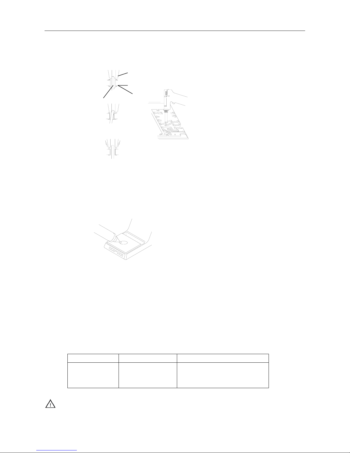
2. Melt the solder: Apply the nozzle to melt the solder after the temperature has stabilized.
CAUTION:
a) Never allow the nozzle to touch the board itself.
b) To confirm that all the solder is melted, observe the inside of the hole and the backside of the PCB. If
this is difficult to do, try slowly moving the lead with the nozzle. If the lead can move, the solder is
melted.
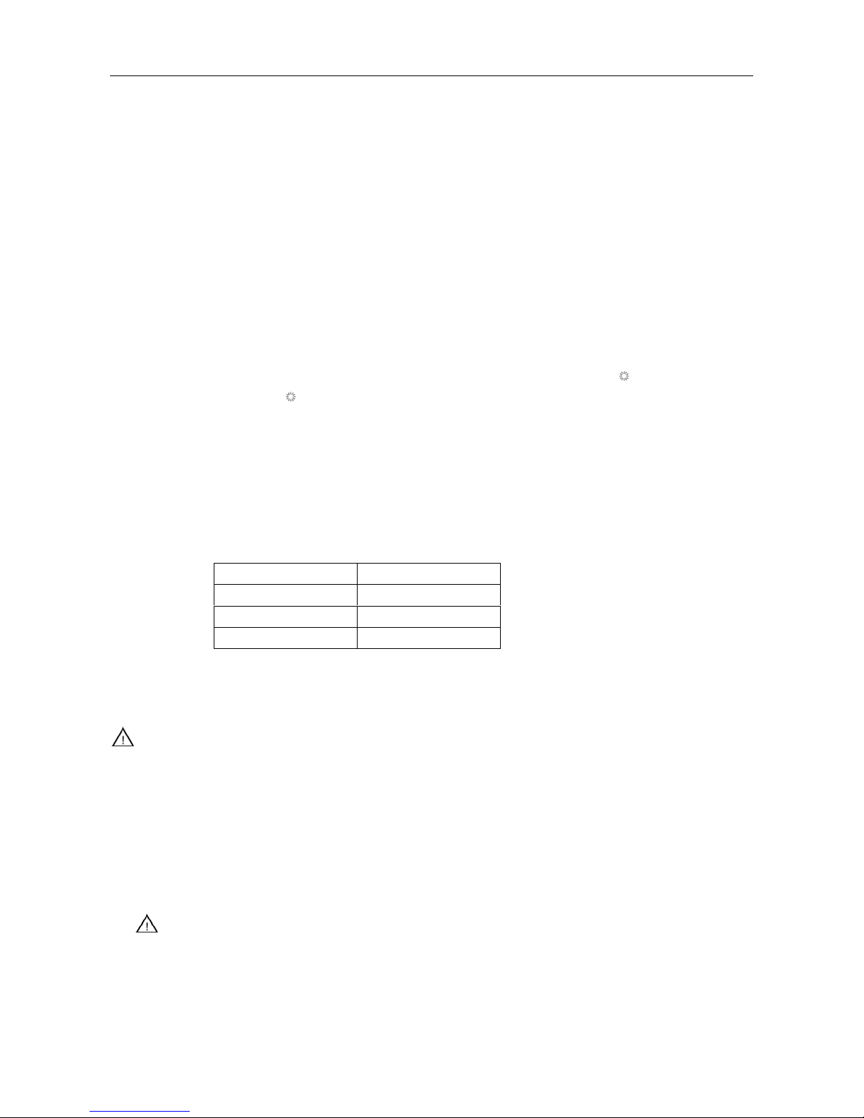
Temperature PCB
280-350 ℃ Single-sided PCB
320-400 ℃ Through-hole PCB
350-450 ℃ Multi-layer PCB
Page 13
12
Nozzle
PCB
Solder
Lead
Move the lead with the
nozzle slowly.
Absorb the solder by moving the lead back
and forth slowly with the nozzle.
c) Never move the lead by force. If it doesn’t move easily, the solder isn’t yet fully melted.
3. Absorb the solder: After confirming that the solder is complete ly melted, absorb the solder by squeezing the
trigger on the gun. After fully absorbing all the sol der, cool the soldering junction in order to prevent it fro m
becoming re-melt.
4. Problems during de-soldering: If solder remains, it must solder the component again and repeat the
de-soldering process as above.
5. Clean the tip of the nozzle: Keep the solder-plated section of the nozzle shiny by coating it with a small
amount of solder. If the tip of the nozzle is coated with oxide, the nozzle’s heat
conductivity will be lowered. Coating the tip with a small amount of fresh
solder ensures maximum heat conductivity.
6.3.4 Cleaning during the Process of Operation
The absorbed solder by nozzle must be cleaned in time to insure the unit work normally.
6.3.4.1 Observing the Indicator
1. Make sure that the hole of the nozzle is open and without jam before observing the indicator which can
indicate the parts of the de-soldering gun need clean or not.
2. Pull the trigger and look at the indicator.
3. If the indicator is red, clean the nozzle and heating element, empty the filter pipe, and replace the filters. If the
indicator is blue, cleaning is not necessary and operations can be resumed.
CAUTION:
z The results of the indicator will not be accurate if the hole of the nozzle is closed or if the solder in the hole
Normal Abnormal Solution
Blue or slight amount
of red can be seen.
More than half of the
indicator is red.
If the indicator is more than half red, replace
the filter and clean the nozzle and the inside
of the heating element.
Wipe away any oxide or old solder from the nozzle
by the hole in the center of the sponge.
Page 14
13
of the PCB is not melted.
z Clean the nozzle and heating element with the cleaning pin if there is a noticeable drop in suction efficiency.
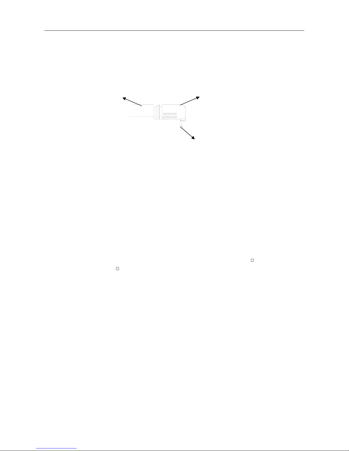
6.3.4.2 Replacing the Filter Pipe
Replace the filter pipe as shown step ①~③. During operation, the filter pipe is very hot. Wait until the filter pipe
is cool before replacing the filter.
6.4 Operation of the SMD Rework Tool
6.4.1 Enter or Exit from the State of the SMD Rework Tool
1. Turn on the power switch, click“TOOL3” key into the single displaying state of SMD rework tool.
2. If displaying “-” at the SMD rework tool window, which means the SMD rework tool is in the shutting state
and cannot be operated. At the state, if pressing “TOOL3” key about three seconds, the SMD rework tool
window will shows “ON”, which means the SMD rework tool can work normally.
3. Pressing “TOOL3” key again, the SMD rework tool window will shows “OFF” and then “-”, which means the
SMD rework tool has been into the shutting state.
4. If displaying “---” at the SMD rework tool window, which means the SMD rework tool is in the sleeping state.
The SMD rework tool comes to heat up when waking up from the sleeping state, the “
” lights and when the
temperature is stable, the “
” flickers.
6.4.2 Set the Temperature and Airflow of the SMD Rework Tool
Click “TOOL3” key into the single displaying window of the SMD rework tool, and then click “TEMP▲” or
“TEMPT” key to change the temperature and click “AIR▲” or “AIRT” key to change the airflow (refer to the
temperature and airflow setting).
6.4.3 Operation
NOTE: the sucking nozzle of the rework handle cannot suck chip when the d e-soldering gun is sucking solder
because the bump has been used by the de-soldering gun.
1. Select the appropriate nozzle to install on the handle.
2. Take up the handle and the handle can come into the normal work state (if it is in sleeping state).
3. Turn the knob on the middle of the handle to make the sucking pole out or in. install an appropriate sucking
nozzle on it.
4. When de-soldering the chip, once the solder has melt, click “VACCUM” key, it can start-up the bump and
then use the sucking nozzle to suck the chip. Close the bump by clicking “VACCUM” key again.
① Pull down
②Automatically spring
③ Replace the entire filter pipe with the provided
backup filter pipe.
Page 15

14
5. After finishing work, take down the handle on the holder. When the temperature is less than 100℃, it enters
into the sleeping state.
CAUTION:
For prolong the life of the heater and protect the safety of the chip, use as low temperature as possible and as
big airflow as possible if it can finish the de-soldering work.
6.5 On Line with the Hot Plate
This unit can work together with a kind of the preheat plate by the special connection cord.
Take out the cord from the package. One end of the cord connects with the six-pins socket on the back of the unit,
and the other end connects with preheat plate. Detailed operation can refer to the manual of the preheat plate.
Ⅶ. Temperature Calibration
1. If the unit is locked by password, it will not be able to calibrate the temperature and you must input the right
password.
2. The corresponding temperature should be recalibrated after replacing the de-soldering gun or heating element
or nozzle or tip every time. It adopts digital calibration mode and input the revision value is input by pressing
button, make the adjustment simply and quickly.
3. Method of recalibrating temperature: Use the thermometer to calibrate, and it is precise comparatively.
① Set one kind tool’s temperature to a certain value(300℃).
② When the temperature stabilizes, measure the temperature with thermometer and write down the reading.
③ In the single displaying state, press the “TOOL1” or “TOOL2” or “TOOL3” and not loosen, and then
press the“TEMP▲”and“TEMP T”keys simultaneously, the unit enters into calibrating temperature
mode. The LCD shows “CAL” about 2seconds and then into the temperature-inputting interface.
z Calibration the temperature of the soldering iron: press the “TOOL1” key not loosen, and then
press the“TEMP▲”and“TEMP T”keys simultaneously, the unit enters into the calibrating
temperature mode of the soldering iron.
z Calibration the temperature of the de-soldering gun: press the “TOOL2” key not loosen, and
then press the“TEMP▲”and“TEMP T”keys simultaneously, the unit enters into the calibrating
temperature mode of the de-soldering gun.
z Calibration the temperature of the SMD rework tool: press the “TOOL3” key not loosen, and
then press the“TEMP▲”and“TEMP T”keys simultaneously, the unit enters into the calibrating
temperature mode of the SMD rework tool.
④ At the moment, the digit of LCD display temperature is flashing. Press the“TEMP▲”or“TEMP T”
key to select the value and input the reading of thermometer, and the inputting method is the same as
temperature setting.
⑤ Press“VACUUM”key. Here, the whole calibration operation has been finished.
⑥ If the calibration is successful, the LCD shows “OK” and return to work state.
⑦ If the temperature still has deflection, you can repeat calibration in accordance with above steps.
z Recommend using the 191/192 thermometer for measuring the temperature.
Page 16

15
Ⅷ. Error Messages
Various error messages will be displayed when there are some problems with the parts.
Sensor Error: If there is a failure in the sensor or anywhere in the sensor circuit, “S-E” will be
displayed and power to the part will be cut off.
Heater error:If there is a failure in the heater element or anywhere in the heater circuit, “H-E” will be
displayed and power to the part will be cut off.
Motor error: If there is some malfunction in the blower or in the blower circuit, the display window
will display “ERR” and without wind blowing from the handle.
For Example: Select “TOOL3” and in the state of SMD Rework System.
When displaying “H-E”, which means the heating element has some malfunction of the rework handle
and it needs to check the heater and its circuit.
When displaying “S-E”, which means the sensor has some malfunction of the rework handle and it
needs to check the sensor and its circuit.
Ⅸ. Care and Maintenance
9.1 Maintenance of the Soldering Iron
9.1.1 Tip’s using caution
1. High soldering temperature can degrade the function of the tip and use the tip with the lowest possible
soldering temperature. The excellent thermal recovery characteristics ensure efficient and effective soldering
event at low temperatures. This also can protect the sensitive components from thermal damage.
2. When using the soldering iron continuously, be sure to loosen the tip and remove all oxides on the tip at least
once a week. This helps prevent reducing of the tip temperature.
3. Never keep the soldering iron at high temperature for a long time when not using,. Because the tip will be
covered with oxide that can greatly reduce the tip's heat conductivity.
4. Wipe the tip and coat it with fresh solder after using. This helps to prevent tip oxidation.
5. Clean the tip regularly with a cleaning sponge. Oxides and carbides deriving from the solder and the flux can
form impurities on the tip. These impurities can result in defective joints or reduce the heating conductivity of
the tip.
6. Use fine tips only when necessary. The plating on fine tips is less durable than the plating of the blunter tips.
7. Do not use the tip as a detecting tool. Bending the tip can cause the plating to crack and shorten the tip’s life.
8. Use the minimum activation flux necessary to do the job. Higher activation flux is more corrosive to the tip
plating.
9. Don’t apply pressure to the tip. More pressure does not equal more heat. To improve heat transfer, use solder
to form a thermal bridge between the tip and the solder joint.
9.1.2 Check and Clean the Tip
1. Set the temperature to 250℃.
S - E
H - E
ERR
Page 17

16
2. When the temperature stabilizes, clean the tip with the cleaning sponge and check the condition of the tip.
3. If there is black oxide on the solder-plated portion of the tip, coat new solder (containing flux) and then wipe
the tip on the cleaning sponge. Repeat until the oxide is completely removed and then coat with the new
solder.
4. If the tip is deformed or heavily eroded, replace it with a new one.
9.1.3 Renew a de-tinned tip
1. Why does a de-tinned tip fail to work?
A de-tinned tip is one not wetted with solder. This exposes the plating to oxidation and degrades the heat
transfer efficiency of the tip.
2. Detinning is caused by:
(1) Failure to keep the tip coating with fresh solder while not in using.
(2) High temperatures.
(3) Insufficient melting in soldering operations.
(4) Wiping the tip on dirty or dry sponges or rags. (It should use a clean, wet, industrial grade, sulfur-free
sponge.)
(5) There are impurities in the solder, iron plating, or on the surfaces to be soldered.
3. Renew a de-tinned tip
(1) Remove the tip from the handle after the tip cooling down.
(2) Remove the dirty and oxides from the tip with 80-grit abrasive polyurethane foam stock or a 100-grit
emery.
(3) Wrap the stannum including rosin (φ0.8mm or larger) around the newly exposed iron surface, insert the
tip into the handle, and turn on the power switch.
CAUTION:
z Never file the tip to remove oxide.
z Proper daily care can prevent the tip from de-tinned.
9.1.4 Check and Replace the Soldering Iron
When there is something wrong with soldering iron, you can check and test it. If it is broken, replace the broken
element.
9.1.4.1 Check the Soldering Iron
Pull out the plug and measure the resistance value between the pins of the connecting plug when the heating
element cooling down to the room temperature.
(1) If the values of ‘a’ and ‘b’ are different from the values in the following table, replace the heating element or
sensor or cord assembly. Refer to the following steps.
(2) If the value of ‘c’ is over the below value, remove lightly the oxidation in the joint part of the tip and the heat
element with sandpaper or steel wool.
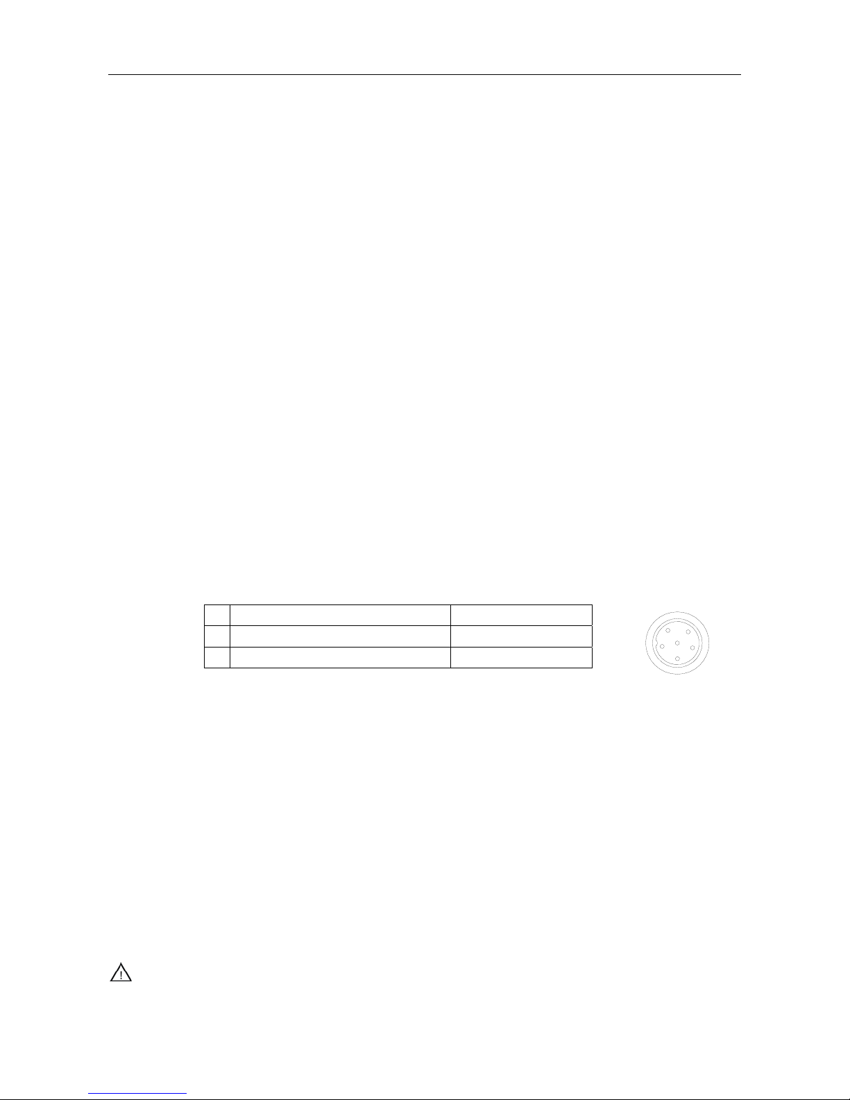
a. Between pins 4&5 (Heating Element)
Under 4Ω(Normal)
b
. Between pins 1&2 (Sensor)
Under 10Ω
c. Between pins 3& Tip
Under 2Ω
1
6
3
5
4
2
Page 18
17
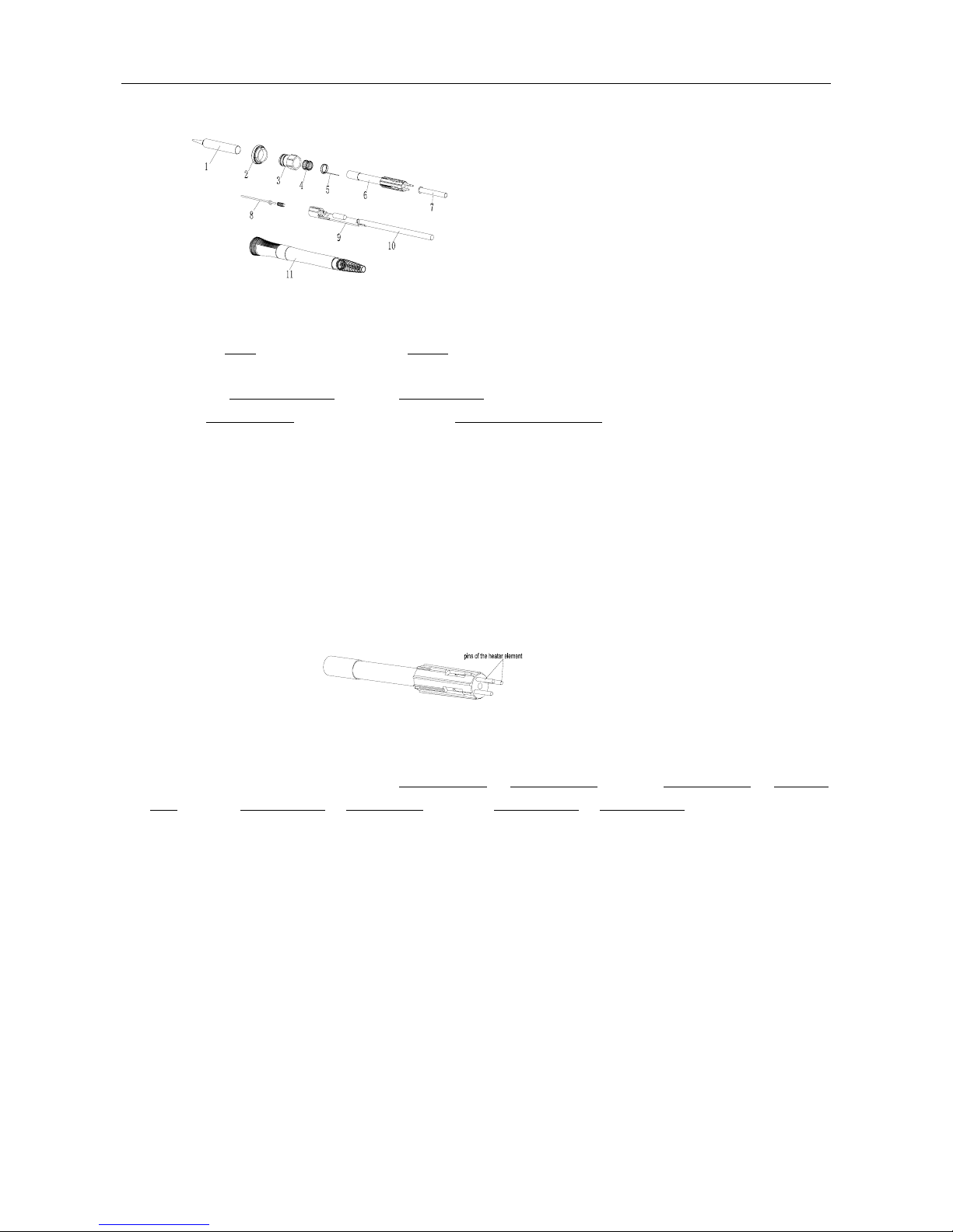
9.1.4.2 Disassembly the Soldering Iron Handle
1. Turn the power switch off and disconnect the power plug. Disconnect the handle connector fro m the station,
and disassemble it after it cooling down.
2. Pull out the tip①. Turn anticlockwise the ring② and take it down.
3. Pull out the inlay piece③ towards the tip way.
4. Take out the heater element⑥
from the iron handle⑾ towards the tip way.
5. Push the handle cord⑩
forward lightly, until the connection cord PCB⑨ has been push out.
6. Don’t use metal tools such as pliers to remove the heater element or the tip enclosure from the handle instead
of using heat resistant pad.
9.1.4.3 Checking the Heating Element
Measure the heating element when it comes back to room temperature:
1. Resistance value of heating element (cord shield) under 4Ω.
2. Resistance value of sensor (Red and Green wire) under 10Ω.
3. If the resistance value isn’t normal, replace the heating element.
9.1.4.4 Change the Heating Element or the Sensor
1. Measure the resistance values between pin4 and pin1 or pin4 and pin2, between pin5 and pin1 or pin5 and
pin2, between pin6 and pin1 or pin6 and pin2, between pin6 and pin4 or pin6 and pin5. If they are not ∞, the
heating element and sensor or vibrator switch are touched. This will damage the PCB.
2. Measure the resistance value ‘a’, ‘b’ and ‘c’ (refer to the above form) to confirm that the leads are not twisted
and that the grounding wire is properly connected.
3. Ensure the pins have inserted to the end.
9.1.4.5 Check the Handle Cord of the Soldering Iron
Check the resistance between the pins of the plug and the wires on the terminal. The value should be 0. If it is
greater than 0 or is ∞, the cord should be replaced.
Pin1: Blue Pin2: Red
Pin3: Green Pin4: Shielded Conductor
Pin5: Lining of the Shielded Conductor (White) Pin6: White
9.2 Maintenance and servicing of the De-soldering Gun
Page 19

18
Diameter of hole is widened through erosion.
Solder plating
Properly maintained, the de-soldering gun should provide years of good service. Efficient de-soldering depends on
the temperature, and the quality and quantity of the solder and flux. Perform the following service procedures as
indicated by the conditions of the gun’s usage.
WARNING:
Since the de-soldering gun can reach a very high temperature, please work carefully. Except when cleaning
the nozzle and heating element, always turn the power switch off and disconnect the power plug before
performing any maintenance procedure.
9.2.1 Daily maintenance
1. Clean the solder and flux in the suction and the hea ter el em ent.
2. After cleaning the suction nozzle with the sponge, coat a ne w solder at its plate to protect the solder plate.
3. The filter is expendable, and it often should be replaced to ensure the suction is normal. Pull out the hose each
side filter take out it, replace a new one (refer to the connection).
9.2.2 Servicing the de-soldering gun
CAUTION:
The de-soldering gun will be extremely hot. During the maintenance, please wear gloves and
work carefully.
1. Inspect and clean the nozzle.
(1) Plug in the power cord, turn the power switch on and let the nozzle heat up.
(1) Clean out the hole of the nozzle heat up.
(2) Check the condition of the solder plating on the tip of the nozzle. If it is slightly worn, recoat the tip
with fresh solder to prevent oxidation.
(3) Check the condition of the surface and inside hole of the nozzle. If either is worn or eroded, or the inside
diameter seems unusually wide, replace the nozzle.
Note: The cleaning pin will not pass through the nozzle until the solder inside the nozzle is completely
melted. Please use the proper sized cleaning pin for the nozzle diameter.
CAUTION:
z Unfortunately, it is often difficult to observe this condition. Therefore, if desoldering efficiency goes
down and all other parts run in well, the nozzle is probably eroded and should be replaced.
z The inside hole and the surface of the nozzle is plated with a special alloy. Should this alloy become
eroded by high-temperature solder, the nozzle will not be able to maintain the proper temperature.
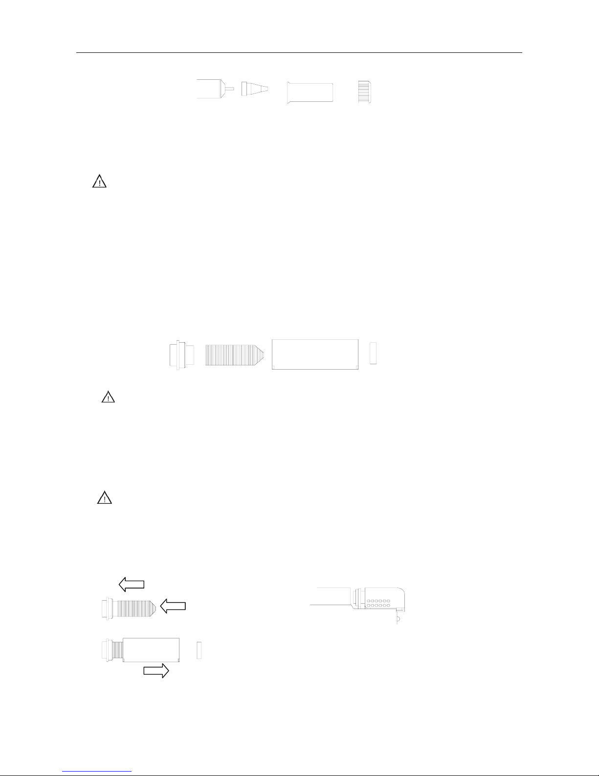
2. Disassemble the heating element
Remove the nut with the heat resistant pad.
The cleaning pin passes completely through the hole.
Page 20
19
3. Clean out the hole in the heating element with the provided cleaning pin.
Be sure the solder in the hole in the heating element is completely heated before cleaning the hole.
CAUTION: If the cleaning pin cannot pass through the hole, replace the heating element.
4. Replace the filters.
(1) Turn off the power switch.
(2) When the filter pipe is cool down to the room temperature and can be touched, push down the release
knob at the back of the gun and remove the filter pipe.
(3) Inspect the front holder: if the front holder is stiff and cracked, replace a new one.
(4) Inspect the spring filter: the spring filter must replace a new one if it has collected two-part solder.
(5) Inspect the ceramic paper filter(S). the ceramic paper filter(S)must replace a new one when it is stiff
with flux and solder.
CAUTION:
The filter pip is very hot during the work. The filter change must be done after it has cooled down.
5. Secure the filter
(1) Attach the spring filter to the fro nt holder.
(2) Attach the front holder to the filter pipe.
CAUTION:
z Be sure the front holder is correctly aligned.
z Use the ceramic paper filter (S) for the filter pipe (gun). Using of the ceramic paper filter (L) in the
filter pipe may cause to break or the power to drop.
6. Assemble the heater element
Heating Element
Nozzle
Element Cover
Nut
Front Holder
Spring Filter
Ceramic Paper(S)
Ceramic Paper Filter (S)
Attach the front holder to
the filter pipe so that it does
not leak air.
Firmly press the back holder
assembly into the filter pipe in
order to properly seat the O-ring
against the pipe.
Page 21
20
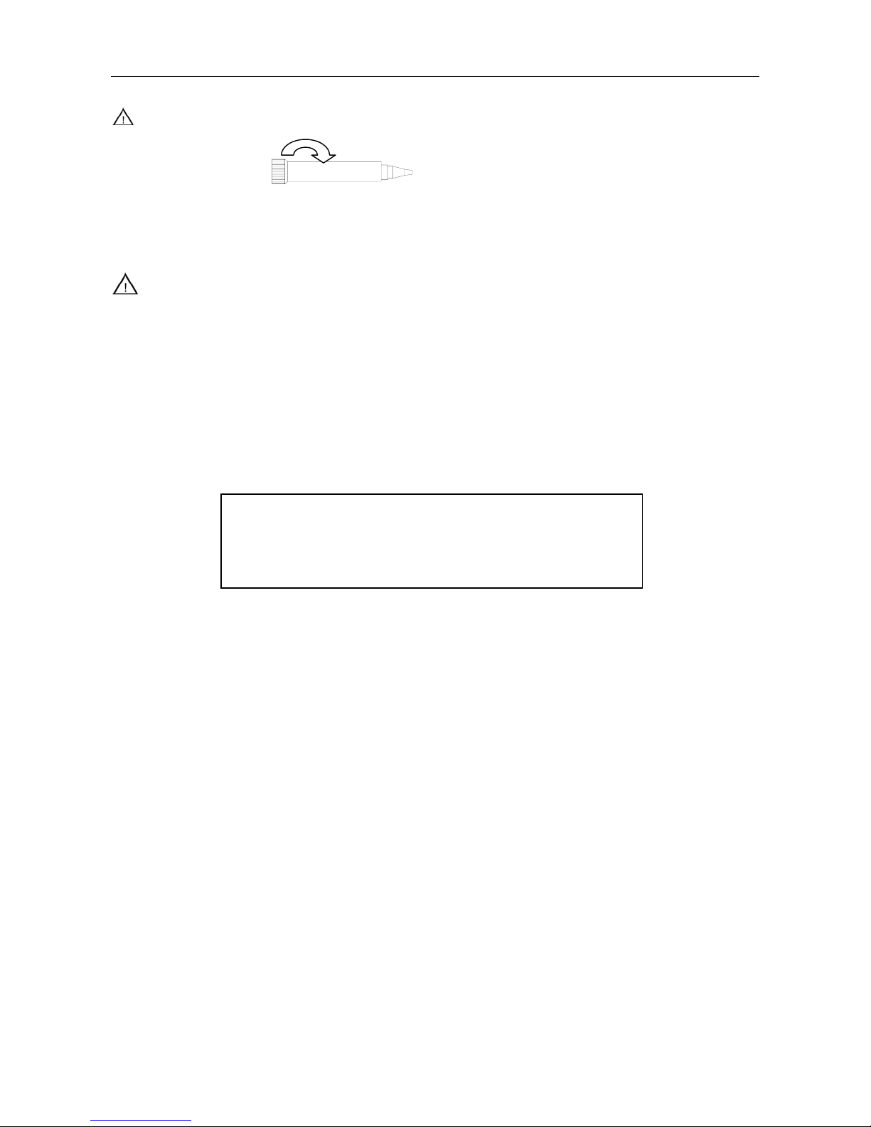
Attach the nozzle and securely tighten the nut with the attached heat resistant pad.
WARNING: If the nut is loose, air will leak and the temperature will drop.
9.2.3 Trouble Shooting Guide of the De-soldering Gun
Warning:
z Disconnect the power plug before servicing. Failure to do so may result in electric shock.
z If the unit is damaged, it must be maintained by the manufacturer, its service agent or similarity qualified
person in order to avoid personal injury or damage to the unit.
1. The solder in the junction is not sufficiently melted
Check 1: Temperature is not high enough.
The following parts require a greater heat capacity to de-soldering.
Multi-layer PCB, bilge PCB, frequency modulation of PCB’s grounding wire, semiconductor
PCB, dual way and three terminals switch part with transmitting heat、big type semiconductor
terminal etc.
Check 2: Nozzle is worn out.
When the nozzle begins to wear out, the heating efficiency begins to decline. Check the nozzle.
If the solder plating is damaged, or the nozzle is eroded, replace the nozzle.
2. Suction capability is dropping
Check 1: Replace the filters, and clean the nozzle and the inside of the heating element.
Please refer to the “5.5.2 ”.
Check 2: Air is leaking from the vacuum system.
Air leakage cannot be determined from the indicator. Check the air-tightness of the following
parts and replace that are worn.
(1) Contact point of the nozzle and heating.
(2) Front holder and nearby parts.
(3) O-ring in the back holder.
(4) Soft Hose.
(5) The tie-in of fixing pipe.
(6) Packing and nearby parts.
Check 3: Clean the nozzle with the clean sponge and then coat a fresh solder on the plating
of the nozzle.
3. LED display does not light up.
Check 1: Is the power cord plugged in correctly?
For the above part, suggest use the PCB pre-heater device. Make the temperature
of the PCB heat up to a certain temperature that will not damage the PCB or the
other component, after that, de-soldering. Do not only increase the temperature of
the gun, otherwise too high temperature may damage the PCB and its components.
Page 22
21
Securely insert the power cord into the power supply with grounding socket.
Check 2: Is the fuse blown?
Determine why the fuse blew and eliminate the cause, then replace the fuse.
z Is the inside of the de-soldering gun short-circuited?
z Is the grounding wire touching the heating element?
z Is the heating element lead twisted and short-circuited?
4. Pump cannot operate.
Check 1: Is the cord assembly properly connected?
Reconnect the cord assembly.
5. Solder cannot be absorbed.
Check 1: Is the spring filter full of solder?
Replace it with a new one.
Check 2: Is the ceramic filter hardened?
Replace it with a new one.
Check 3: Is there a vacuum leak?
Check the connections and replace any worn parts.
Check 4: Is the nozzle or hole in the heating element clogged?
Clean it.
6. The nozzle cannot heat up.
Check 1: Is the de-soldering gun cord assembly properly connected?
Reconnect it.
Check 2: Is the heating element damaged?
Replace it. Measure the heating element whether is broken or not as following.
A Between pins 4 & 5 (Heating element)
Under 4Ω(Normal)
B Between pins 1 & 2 (Sensor)
Under 10Ω(Normal)
C Between pins 3&Nozzle
Under 2Ω
7. Heater error, “H-E” is displayed.
Check 1: Is the de-soldering gun cord broken?
Replace it.
Check 2: Is the heating element broken?
Replace the heating element.
Check 3: Is there a nozzle on the gun?
Assemble a nozzle on the gun.
8. The temperature cannot be set.
Check 1: Is it locked by password?
Enter into the setting password.
9.2.4 Replacing the Heating Element
WARING: unplug the power cord before starting this procedure.
The resistance value of a working heating element is below 4Ω. If the value is outside the range, replace the
1
6
3
5
4
Page 23
22
heating element.
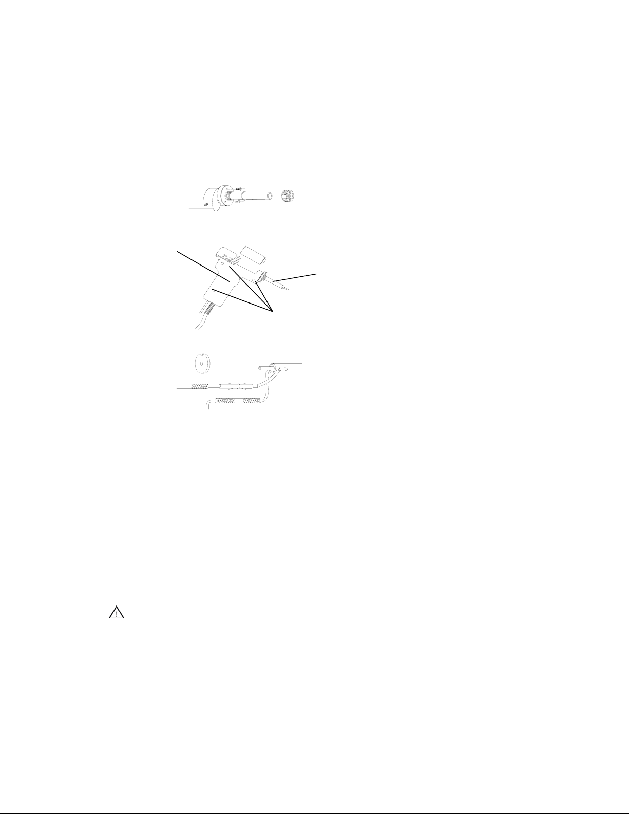
1. Disassemble the heating parts.
2. Separate the housing.
3. Detach the terminal and remove the heating element.
4. Insert a new heating element and reassemble.(Heating element36V-90W
5. Recalibrate the temperature.
The resistance of new heating element varies, resulting in variations in operating temperatures. It is necessary to
recalibrate the temperature every time the heating element is replaced. (See the Calibrate temperature)
9.3 Parts Assemble and Disassemble of the SMD Rework
9.3.1 Nozzles Assemble and Disassemble
1. Assembly:Select one befitting nozzle and insert it into the outlet’s steel pipe. Press it with hand until the
nozzle has been locked. It can be used after the nozzle has been fixed reliably.
2. Change: Take the handle down from the holder after the nozzle has cool down. There is a slot between the
nozzle and the outlet’s steel pipe. By the slot, put the handle on the disassembly plate of the nozzle that is
fixed at the holder. After that, fix the holder with one hand and pull out the nozzle. Change another nozzle.
CAUTION: Change the nozzle after it has cool down.
9.3.2 Replacing Heating Element of the SMD Rework
1. Replace the heating element after the handle has cooled down.
2. Screw down the fixation screws in handle and then take off the handle house.
3. As shown in the diagram, move back the spring in the handle module and take out the steel tube.
4. Cut off the strap, disconnect the sensor cord and the connector, ground cord and ground socket. And then take
out the steel tube and the broke heater element.
Remove the filter pipe
Housing
Unscrew the screws
Detach the terminal
Pad
Unscrew the fixing screws
Page 24

23
5. Wrap the mica on the new heater element and insert into the steel tube. It is better to right insert into the steel
tube and cut off the unwanted mica.
CAUTION: The sensor cords of heater element putting on the red and yellow hot shrinking tubes are on
the opposite part of the ground cord.
6. Reassemble the handle according to the opposite order of disassembling. The heater part of the heater element
must be insert into the end. The sensor cord has polarity and it must connect with the same color.
9.4 Replace the Fuse
1. Unplug the power cord from the power receptacle.
2. Remove the fuse holder and take out the broken fuse.
3. Replace the fuse. Put the fuse holder back in place.
Page 25
24
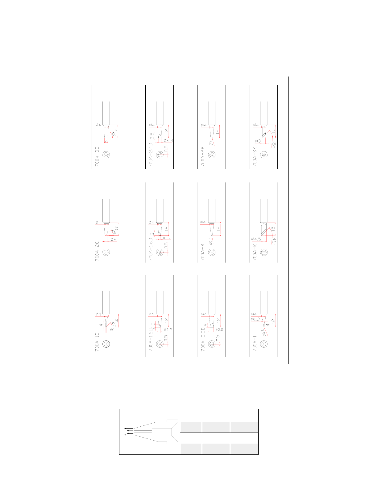
Ⅹ. Replaceable Parts
10.1 Tips
10.2 Sucking Nozzle
P/N φA(mm)
0.8A1004
A1005
A1006
1.0
1.3 3.0
2.5
2.3
φB(mm)
ΦA
ΦB
Page 26
25
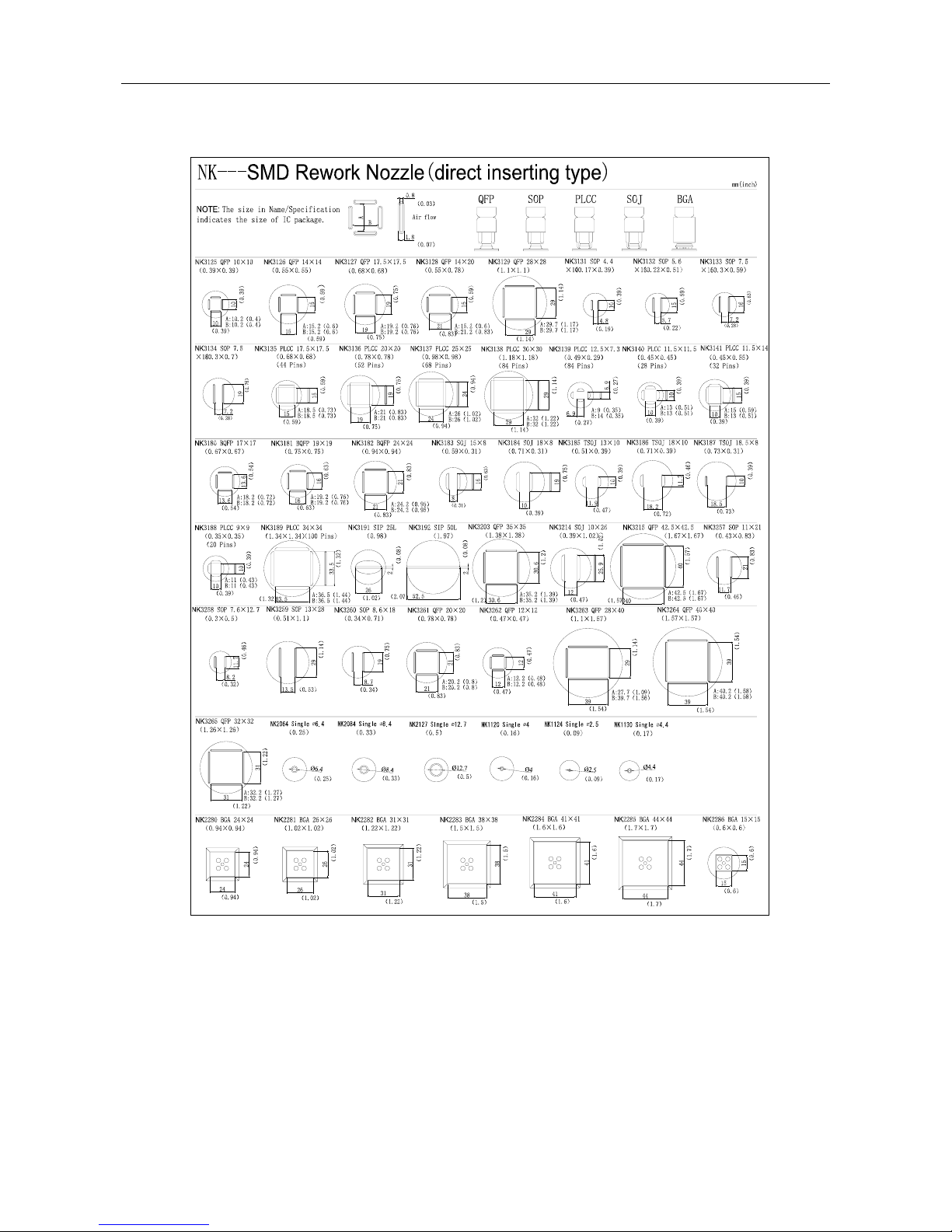
10.3 NK- SMD Rework Nozzle
 Loading...