

Page 1

DSF-73E
Motorized Solder Wire Feeder
Instruction Manual
Thank you for purchasing the solder wire feeder. Please read this
manual before operating the unit. Store this manual in a safe, easily
accessible place for future reference.
Page 2

The unit is an automatic motorized solder wire feeder. It is suitable for variety of
soldering stations and soldering irons. Only need one hand to operate and it is
easy to operate. With step motor, the feeding speed and time, returning length and
feeding interval time are all adjustable and steady, perfect soldering effect and
high efficiency.
Power Consumption 20W
Motor Step Motor
Feeding Speed 2.7mm/s~27mm/s
Feeding Interval Time 0~2.7s
Returning Length About 0~25mm
Feeding Mode Auto. (1~9) / Manual (0)
Dia. of the solder wire 1.4/1.6/1.8/2.0 (mm)
Weight of solder wire usable ≤1Kg (r oll)
NOTE: In order to choose feeder tube and wire diameter ring exactly, please
mark the sold ering iron ty pe and wire diameter when purchasi ng the u nit.
Automatic self-feeder that can match a variety of soldering stations and
soldering irons.
Auto and manual controlled feeding can be optional. It is easy to operate and
only wit h one h an d.
Feeding speed, time and interval time are all adjustable, further more it is
design ed w it h ret u rn i ng fun ct i on to re d u ce sol de r wir e co n sum p ti o n.
Both of Pedal switch an d Ma n ual swit ch c an b e us e d.
ESD safe by design to avoid damaging the sensible electronic elements
because of the stati c.
SECTIONⅠ Summary
SECTION Ⅱ Specification
SECTION Ⅲ Characteristics
Page 3
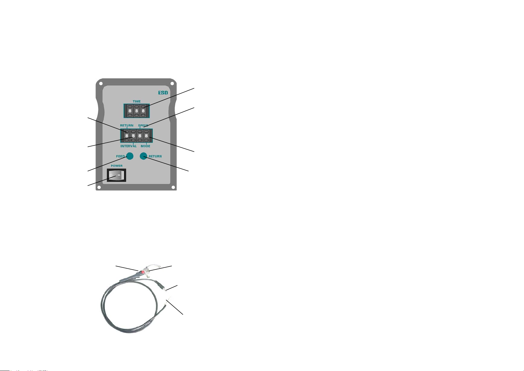
Speed setting switch
Returning switch
Feeding switch
Interval-time setting switch
Returning length switch
Power switch
Feeder tube head
Manual switch
Feeder tube assembly
Page 1
Page 2
SECTION Ⅳ Panel Picture
Time setting switch
Mode setting switch
SECTION Ⅴ Installation
Before installation, please check the parts and make sure whether the power
supply voltage accords wit h the namepla t e.
1. Install feeder tube assembly
Connector
Plug
Page 4
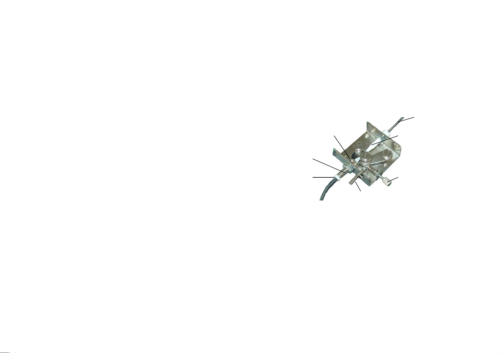
Solder wir e
Handspike
Guide tub e of so ld er wire
Feeder tube head
Page 6
6. Feeding Pressure Setting
When the solder wire cannot be sent out automatically because of the
inadequate feeding pressure, you can clockwise adjust the pressure adjusting
screw on the t op of unit to in crease feeding pres s ure.
When the solder wire is twiste d becaus e of too strong fe eding pressure, you can
adjust the pr es su re a dj us ti ng scr ew an ti cl o ck wi s e.
SECTION Ⅶ Operations
1. It can press the key “FEED” or “RETURN” to adjust the length of the
solder w ire.
FEED: Click the “FEED” key, the system will feed the solder w i re once. If
pressing the “FEED” key and not loosen, it will feed the solder
wire continually.
RETURN: Click the “RETURN” key, the solder wire will return once
about 3m m .
NOTE: During the working state of mode 0~9, the system will not run
the process sending from the “FEED” and “RETURN” keys.
2. Do corresponding operations i n accor dance with the chosen Feeding Mode.
1) Manual — Th e M ode switch is set as 0
Turn on power switch. Step on Pedal Switch or press the red Touch
Switch, and the unit works. After loosing it, returning once and then
stop working.
Feeding Time and Fee ding Interval and Feeding Mode are all useless
when the Feeding Mode is se t as manual.
2) Auto — The Mode switch is set as during 1~9
Turn on Power Switch. The unit will work according to the setting
parameters when stepping on pedal switch or pressing Touch Switch
once. A ll function s ar e us ef ul .
Unscrew the fixing screw on the top cover of unit, insert the feeder tube head
of the feeder tube into the directional fixing tube of the feeder tube head, and
then tighten the scr ew.
Insert t he pl ug int o th e jack on the b ack cover of the unit.
2. Install the solder wire
Fixing screw
Directional fixing tube
Pressur e adjusting screw
(1) Pull the solder wire axis through the framework of solder wire and place it
to the s older w i re holder at the back of unit. Make th e notch on each side of
solder wire a xis lock into th e solder wire holder.
(2) Pull out the solder wire head and insert it into the guide tube of solder wire
behind the top. For the solder wire coming into the feeder tube head easily,
push handspike to widen th e gap bet ween the two r unning gear wheels.
(3) Set the Feeding Mode as manual “0”, and insert power plug and turn on
power sw itch “POWER”. Make the Feede r Tube as straight as possibly,
press down the manual switch (the red Touch Switch) until the solder wire
is sent out.
3. Install Soldering Iron
Take down connector plugs of the soldering iron from the soldering station
Page 5

and then install the feeder tube c onnector on the solde r ing iron.
Page 3
Page 4
(1) Firstly, loosen the f i xing sc rews of t he fee der tube connector.
(2) And then install the handle into the feeder tube connector. The connector
is installed in the not ches o n the top of the handle.
(3) After that, screw down the fixing screws on the connector. Turn the
connector to adjust the combined location of between the feeder tube
and the soldering tip, and at last connect the soldering iron to soldering
station.
Note:
When pressing down the red touch switch (Manual switch), if the
solder wire cannot be sent out auto matically, it needs to adjust the
feeding pressure―pressure adjusting screw (Refer to parameter
setting).
The feeder tube cannot be bended overly because the solder wire
may b e block ed.
When the unit is working, the soldering tip’s temperature is very
high, please be careful, not to be scalded.
Make sure the power voltage is according with the working voltage
of the u nit.
SECTION Ⅵ Set Parameters
Parameter is set by digital switch on the panel. Press “+” button on the digital
switch and the match digit will increase one. Similarly, press “-” button, and
the match dig i t will decrease one.
1. TIME — Feeding Time Setting
Press the feeding time switch “TIME” to set the suitable digit in accordance
with working demand. Feeding Time is designed with thr ee digits.
000 to 999 denotes the feedi ng tim e is about 0.15mm~150mm.
Example: When the digit is set as 000, the feeding time (feeding length) is
0.15m m. When the digit is set as 001, the feedi ng tim e ( feeding length) is about
0.3mm. ……. When it is set as 999, the feeding time is longest and about
150mm.
2. RETURN — Returning Length Setting
Press the returning length switch “RETURN” to set the suitable digit in
accordance with wo rking d emand.
Returning length is design ed with one digit.
0 to 9 denotes the returning length is about 0~25mm (returning time is about
0~0.9s). If the “RETURN” is not as “0”, the solder wire will return every
feeding.
Example: W hen the digit is set as 0, the returning length is 0mm. When the
digit is set as 1, the returning length is about 2.8mm (the returning time is about
0.1s). ……When the digit is set as 9, the returning length is about 25mm(the
retur ni ng tim e is ab o ut 0. 9s ).
3. INTERVAL — Feeding Interval Time Setting
Press the feeding interval time switch “INTERVAL” to set the suitable digit in
accordance with working demand. Feeding Interval Time means the interval
time between every feeding when the aut omatic feeding is over two times.
Feeding Int e rv al Time is designed w it h on e dig i t.
0 to 9 denotes the int erval time is about 0~ 2.7seconds.
Example: When the digit is set as 0, which means the unit will feed solder wire
continua lly without stop. When the digit is set as 1, the i nterval ti me is about
0.3second. When the digit is set as 2, the interval time is about 0.6second.
When it is set as 9, the i nterval time is longest with about 2.7se conds.
4. SPEED — Feeding S peed Setting
Press the feeding speed switch “SPEED” to set the suitable digit in accordance
with working demand. Feeding speed is designed with one digit.
0~9 denotes the feeding speed is about 2.7mm/s~27mm/s.
Example: When the digit is set as 0, the speed is slowest with about 2.7mm/s.
When it is set as 9, the speed is fastest with about 27mm/ s.
5. MODE---Feeding Mode Setting
Press t he feed ing mode switch “MODE” to choose s uitable digit.
Feeding Mode is designed with one digit and the setting method is the same as
above. The digital match functi on as followings:
0: Manual Feeding--- the manual feeding is control by the manual switch. The
solder wire wi ll not stop fee ding un t i l loosen the manual switch.
1: Auto Feeding one time 2: Auto Feeding two times
3: Auto Feeding three times 4: Auto Feeding four times
5: Auto Feeding five times 6: Auto Feeding six times
7: Auto Feeding seven times 8: Auto Feeding eight times
9: Auto Feeding nine ti mes
After each fe eding, the solder wire will return.
Page 6

Page 5
 Loading...