

Page 1

Digital Hand-Held Static Field Meter
Operation and Maintenance
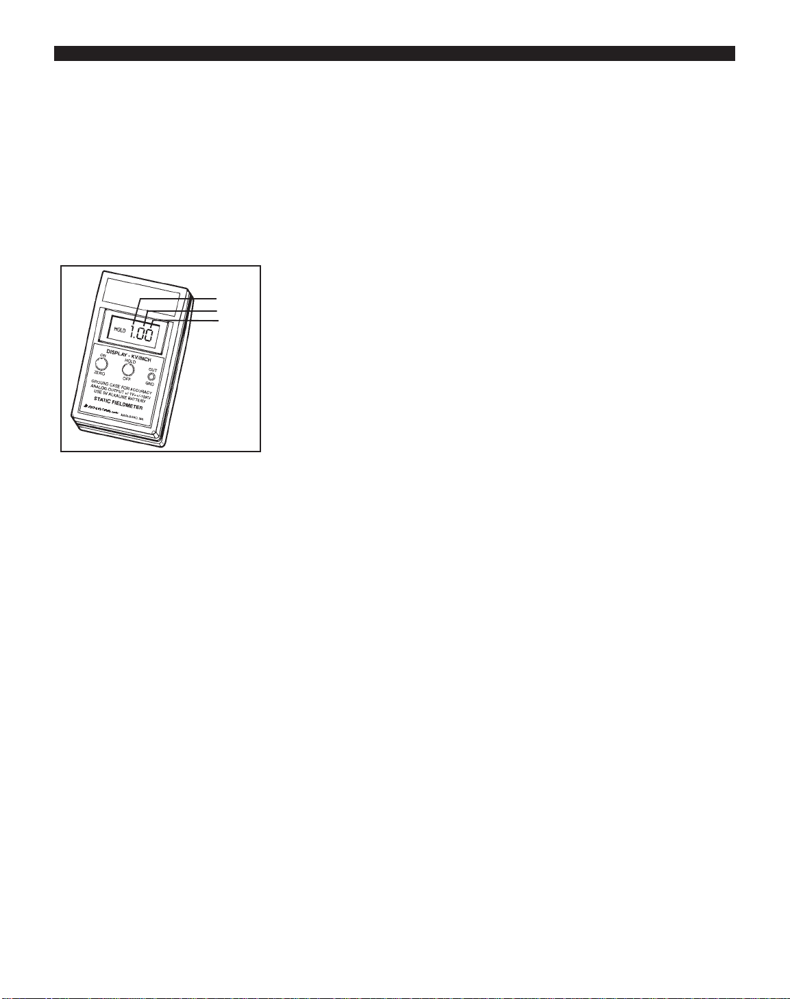
Figure 1. 42721 Digital Static Field Meter
• The target must be large relative to
the measurement distance. It should
be at least 5" x 5" for best results.
Inspection
Remove the items from the shipping
carton and inspect for damage. Included
with each unit should be:
1 42721 Digital Field Meter
1 carrying case
1 9V alkaline battery
Operation
ZEROING THE FIELD METER
1. The Field Meter needs only to be
zeroed at the time you first use the
instrument. It will maintain this value
while the battery is charged.
2. Press the ON/ZERO button and
release. The LCD display is activated
and LED rangefinder lights begin to
flash.
3. Ground the operator by using a wrist
strap or a footgrounding device. You
can also ground the unit directly via
a ground cord. The case of the
instrument is conductive and is the
reference for the measurement.
4. Face the Field meter away from
charged objects and press the
ON/ZERO button. Hold until the
display reads zero. The instrument
may also be zeroed by pointing it
toward a known grounded surface
(such as the palm of the opposite
hand) and depressing the ON/ZERO
button. Care should be taken not to
contact the recessed sensor plate,
however the amount of spacing
between the instrument and the target
is not critical when zeroing the
instrument.
PS-2061 6/05 Page 1 of 4
Description
Our 42721 is a high quality, portable
non-contacting static fieldmeter which
produces consistently accurate readings
with ease and provides years of troublefree operation. It indicates surface
voltage and polarity on objects up to
±20kV at a spacing of one inch with an
accuracy of 5% of the displayed value.
It is chopper-stabilized for use under
almost any conditions including ionized
environments. Also featured are a pushbutton auto-zero and a push-button hold
function. Aunique flashing LED
rangefinder system provides accurate
positioning of the meter from the target.
Its accuracy is dependent upon four
factors:
• Grounding of the Field Meter via a
ground cord or a grounded operator.
• The Field Meter must be properly
zeroed.
• The measurement distance from the
front edge of the case to the target or
surface under examination must be
accurately defined.
TAKING READINGS
1. Point the sensor plate toward the
target and move to a spacing of one
inch from sensor plate to target.
Use the LED rangefinder to
determine this distance. The two
LEDs appear to form a stationary
(not moving) circle on the target at
one inch. Note the meter reading. A
source with a negative polarity shows
a minus (-) sign in the display. A
positive source will display no sign.
To hold the reading, click the
HOLD/OFF button briefly. The
present reading is held and the word
"HOLD" appears in the display. The
rangefinder LEDs go off during the
hold period to conserve battery life.
A second click releases the held
reading.
CAUTION: If, as you approach the
target, the indicated field strength
begins to exceed 20kV at a distance
greater than 1", ST
OP! This implies
that the target voltage may be high
enough to create an arc. Proceed with
caution.
For measurements in excess of 20kV,
estimate the distance to the target and
use the following multiplying factors:
Tech Brief
Made in America
© 2005 DESCO INDUSTRIES INC.
Employee Owned
Figure 2. Zeroing the Field Meter
Page 2
At 4", multiply reading by 2 - 40kV
range
At 6.5", multiply reading by 3 60kV range
At 8.5", multiply reading by 4 80kV range
The LED rangefinder system is
calibrated at the 1" distance only.
2. Repeat the above for additional
measurements.
3. To turn the instrument off, press and
hold the HOLD/OFF button for at
least 3 seconds until display readings
disappear.
AUTO SHUTDOWN TIMER
During normal operation (not during
ZERO) a blinking decimal point
indicates the AUTO SHUTDOWN
TIMER is enabled. If the AUTO
SHUTDOWN TIMER is disabled the
decimal point will be on continuously.
Holding down the ZERO button, while
unit is ON, for less than 3 seconds
resets the AUTO SHUTDOWN TIMER
(if enabled). The AUTO SHUTDOWN
TIMER is enabled or disabled by
turning on the unit and keeping the
ON/ZERO button pressed then toggling
the HOLD/OFF button. Enable/disable
of the AUTO SHUTDOWN TIMER is
indicated by the decimal point:
DP on = timer on, DP off = timer off.
AUTO SHUTDOWN TIMER state is
maintained during power off. AUTO
SHUTDOWN TIMER can be
continually toggled as long as the
ON/ZERO button remains pressed, up
to 20 seconds, after which the unit will
turn off. A blinking decimal point
indicates the AUTO SHUTDOWN
TIMER is active. During the last minute
before power off ALL annunicators will
blink at a fast rate. Pressing any button
will reset the timer. Timeout is
nominally 15 minutes.
Operating Notes:
• The case of the instrument is made of
a material which is sufficiently
conductive to provide a grounding
path via the person holding the
instrument or a grounded wrist strap
in contact with the case.
• The output jack accepts a standard
3/32" (2.5mm) monaural phone plug
and is provided in order that the
output of the instrument may be
connected to an oscilloscope, strip
chart recorder, external meter or
other device. The output voltage at
this jack is ±2 volts for full input
(20kV/in. at 1") for high impedance
loads (100 kS or greater). It has an
impedance of approximately 100S.
The shell of this jack may be used to
provide a "hard ground" connection.
• If you press the on/zero button
during operation, the Field Meter
begins the auto zero function and
displays the value. It you do not
complete the auto zero operation, the
meter is not correctly zeroed.
• For extended monitoring of
materials, a +9 volt power supply
(such as Radio Shack #273-1552)
may be substituted for the battery.
Measurement Accuracy
The accuracy of measurement is
dependent on a stable ground reference
and the 1 inch measuring distance as
previously noted. It is also dependent on
the “aspect ratio,” relating the size of
the object to be measured to the
PS-2061 Page 2 of 4
Figure 3. Taking readings in the
“HOLD” mode
measurement distance. This ratio should
be at least 3 for best accuracy, i.e. the
object should be at least a 3 inch square
when measuring at a 1 inch distance.
Accurate measurements may be made at
other measurement distances by scaling
the meter range and observing the
proper aspect ratio. For example, at a
measurement distance of 3 inches, the
object being measured at this distance
should be at least a 9 inch square.
Auditing of Ionization
Equipment with the 42721
Due to its unique measuring circuit the
digital field meter will accurately
operate in an ionized air stream or
ionized field.
We offer a "Portable Ionization Test
Kit" (Item 42755) designed to facilitate
routine auditing and periodic testing of
ionization equipment. The Test Kit is
designed to be used in conjunction with
the 42721 meter. The Field Meter and
test kit combination can be used to audit
an ionizer's overall performance. The
highly portable Test Kit allows the user
to make quick and accurate balance
level and neutralization efficiency
measurements. The Test Kit is sold
separately as item 42755. The Portable
Ionization Test Kit includes a slide-on
adapter plate, a +/- 1000V charging unit
and a durable molded carrying case
along with the Digital Fieldmeter.
In order to test ionization equipment to
an industry recognized standard, we
recommend the test procedure published
by the ESD Association as Standard 3.1.
This standard may be obtained from the
ESD Association, 7902 Turin Road,
Suite 4, Rome, NY 13440-2069, (315)
339-6937.
Thousands
Tens
Hundred
© 2005 DESCO INDUSTRIES INC.
Employee Owned
Page 3
PS-2061 Page 3 of 4
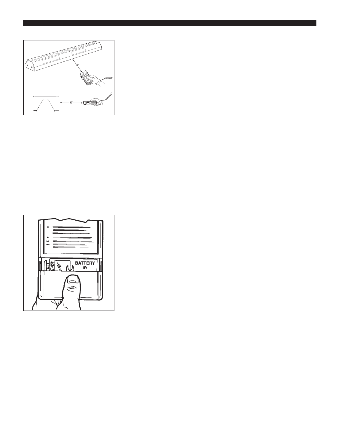
Figure 4. Auditing ionization equip-ment
with the Digital Fieldmeter and the
Ionization Test Kit.
© 2005 DESCO INDUSTRIES INC.
Employee Owned
Maintenance
BATTERY REPLACEMENT
The unit should be off while replacing
the battery. Normal battery life is about
40 hours of use. Replace the battery
when the "BAT" indicator appears in the
display above the "HOLD" indicator
position for more than an instant or
change at least once a year. Dead
battery voltage is approximately 7.2
volts.
Replacement type is Eveready #216 or
equivalent NEMA 1604. An alkaline
type is recommended when long service
life is important. Remove the battery
when storing the instrument for an
extended period of time.
NOTE: After you change the battery
you will need to re-zero the meter.
CLEANING
If the 42721 is used in a dirty or dusty
environment, it may be necessary to
clean the sensor plate to ensure proper
operation.
Foreign materials which may enter the
aperture associated with the input
electrode can generate undesired
signals, offset or drift, thereby impairing
the accuracy and utility of the
instrument. It is imperative that the area
around the aperture be kept
scrupulously clean at all times. This can
best be done by proper care, handling
and storage of the instrument. Loose
dust or other particulate matter may
simply be blown away with low
pressure instrument grade air.
More severe contamination may be
removed by spraying or flushing with
the least practical amount of clean
technical grade isopropyl alcohol. Stand
with instrument on end and allow to dry
thoroughly for several hours. Cleaning
with any solvent should NOT be done
on a routine basis.
Calibration
Our 42721 is calibrated prior to
shipment to NIST traceable standards.
Re-calibration should be performed
annually unless the instrument has been
tampered with or repaired, or more
frequent calibration is specified by
company policy or by contract.
Calibration of the Digital Field Meter
should only be performed by the
factory. Contact our Customer Service
Department for details.
Recommended Reading
SEMI E43-95, RECOMMENDED
PRACTICE FOR MEASURING
STATIC CHARGE ON OBJECTS AND
SURFACES. Published by
Semiconductor Equipment Materials
International (SEMI), Mountain View,
CA, (650) 964-5111.
Specifications
Display:
3 1/2 digits, 0.4" digit height LCD
Response:
<1 sec., 10% to 90% equivalent to 5Hz
output
Range:
± 0.00 to +/- 19.99 kV/inch (25mm)
Accuracy:
± 5% of displayed value,
± 3 counts (LSD)
Environment:
0 - 50°C at 85% RH (non-condensing)
Output:
2.5mm phone jack/plug, ± 2 volts for
full input (2V/20kV/in.)
Battery:
9 volt, NEMA 1604, alkaline
recommended
Accessories:
Carrying case and Tech Brief included.
Charged Plate Adapter available as an
optional accessory for testing air
ionizers
Personal HBM Test Fixture
(Requires the 42723 Charging Plate
to be installed first). The Personal
HBM Test Fixture (Item No. 42722)
turns your model 42721 Digital Field
Meter into a Human Body Model triboelectric charging tester. This kit will
allow you to measure electrical charges
generated on the human body while
walking or moving across an insulative
or conductive surface. It has been
specially designed to measure static
charges produced by walking across
substrates such as carpeting, vinyl
Figure 5. Replacing batteries.
Page 4
floor tile, and sealed concrete. It can
also be used to detect charge generation
on conductive surfaces such as
conductive or dissipative floor tiles and
carpeting. An ESD technician may also
use this tool to verify proper grounding
between a conductive or dissipative
floor surface and a person wearing
personal grounding devices such as foot
grounders. The amount (or size) of the
charge generated will vary from one
human body to another. Other factors
such as humidity, contamination
between the foot and flooring surface,
as well as human body capacitance will
also affect the amount of charge
generated.
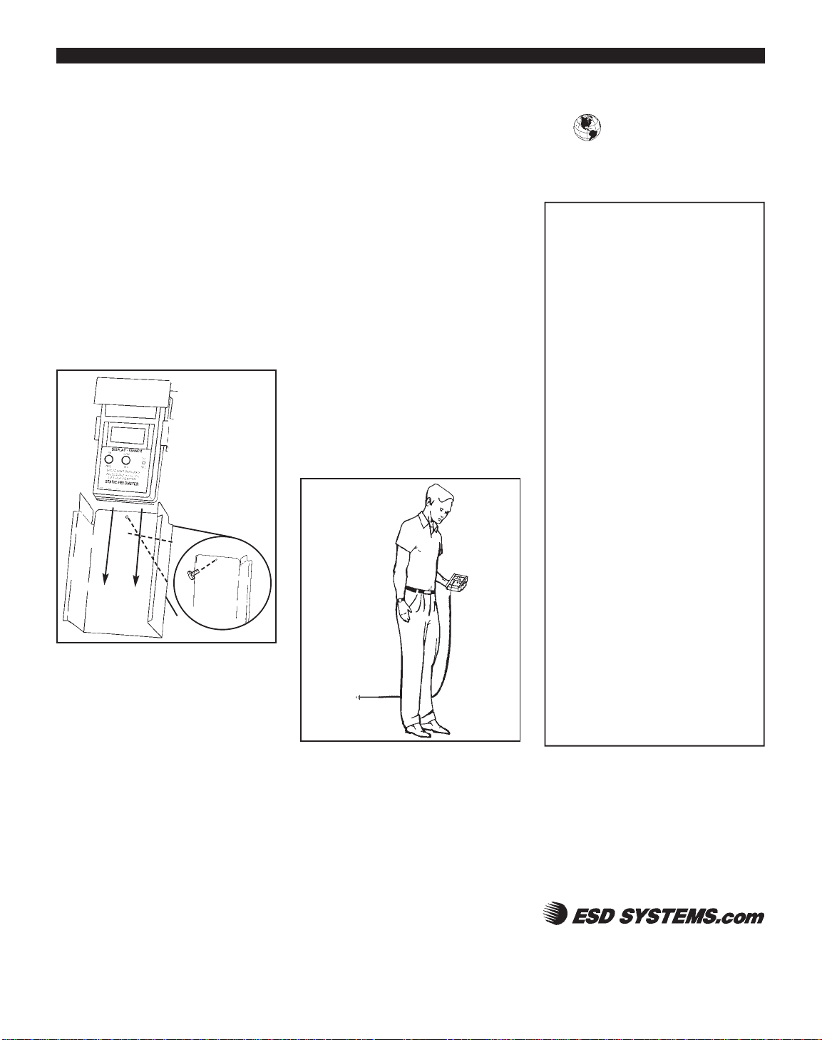
Figure 6. Installing HBM Test Fixture on
42721 Digital Field Meter
INST ALLATION AND REMOV AL
The test fixture is stored in the Survey
Kit with the Digital Field Meter
installed, ready for use. Or, you may
purchase the 42722 HBM Test Fixture
and 42723 Charging Plate separately if
you don’t have a Survey Kit. If the
fixture needs to be removed to allow
use of the Field Meter alone, follow
steps Aand B of the diagram. The
ground cord is located underneath the
test fixture in the Survey Kit. To obtain
the desired result, the ground cord must
be installed onto the Field Meter and
attached to a utility or common ground
point.
432 NORTHBORO ROAD CENTRAL
MARLBORO, MA 01752
PHONE (508) 485-7390
FAX (508) 480-0257
Visit our online
library of Tech Briefs:
http://www.esdsystems.com
PS-2061 Page 4 of 4
METHOD OF OPERATION
In order to obtain the desired test
results, the meter must be properly
grounded as stated in the Installation
and Removal section. Once installed on
the Field Meter, the Test Fixture itself is
isolated from the meter case and ground
and should remain that way.
Cradle the Test Fixture in the palm of
your hand. Once the meter is grounded
and you are standing on the substrate to
be tested, simply walk around, shuffle
your feet or raise a foot, to determine if
the combination of footwear and
substrate produces an electrical charge.
If an electrical charge is generated and
induced onto the human body, the Test
Fixture will transfer that charge onto the
Field Meter, and the amount of the
charge will be registered. If it is
necessary to record the amount of
charge, you can save the result by
simply
Figure 7. Using the HBM Test Fixture to
measure charges on the body.
pressing the Hold button on the front of
the Field Meter, and pressing the button
with an insulated object. This test can
be done regardless of the type of
footwear or substrate combination.
Other items in your ESD Control
Program may also be tested such as
conductive or dissipative chairs. Simply
sit in the chair on the desired substrate
and move the chair back and forth to
determine if the chair and human body
combination produces and electrical
charge.
Limited Warranty
ESD Systems.com expressly warrants that for a
period of one (1) year from the date of purchase,
our Digital Field Meters will be free of defects in
material (parts) and workmanship (labor). Within
the warranty period, the material will be replaced
at our option, free of charge. Call Customer
Service at 508-485-7390 for a Return Material
Authorization (RMA) and proper shipping
instructions. You should include a copy of your
original packing slip, invoice, or other proof of
purchase date. Any unit under warranty should be
shipped prepaid to the ESD Systems.com factory.
Warranty repairs will take approximately two
weeks.
If your unit is out of warranty, ESD Systems.com
will quote repair charges necessary to bring your
unit to factory standards. Call Customer Service
at 508-485-7390 for a Return Material
Authorization (RMA) and proper shipping
instructions and address.
Warranty Exclusions
THE FOREGOING EXPRESS WARRANTY IS
MADE IN LIEU OF ALL OTHER PRODUCT
WARRANTIES, EXPRESSED AND IMPLIED,
INCLUDING MERCHANTABILITY AND
FITNESS FOR APARTICULAR PURPOSE
WHICH ARE SPECIFICALLY DISCLAIMED.
The express warranty will not apply to defects or
damage due to accidents, neglect, misuse,
alterations, operator error, or failure to properly
maintain, clean or repair products.
Limit of Liability
In no event will ESD Systems.com or any seller
be responsible or liable for any injury, loss or
damage, direct or consequential, arising out of the
use of or the inability to use the product. Before
using, users shall determine the suitability of the
product for their intended use, and users assume
all risk and liability whatsoever in connection
therewith.
B. Insert screw from
the back of 42722
HBM Test Fixture.
A. Slide 42721 Static
Fieldmeter down into
42722 HBM Test
Fixture.
NOTE: 42723
Charging Plate is
required to use the
HBM Test Fixture.
© 2005 DESCO INDUSTRIES INC.
Employee Owned
 Loading...