

Page 1

Operating Instructions Revision: MON-001
Factory: Agent:
ESCO Tool Company, a Unit of ESCO Technologies, Inc.
75 October Hill Road Ste A, Holliston, MA 01746 USA
Tel 508.429.4441 | Fax 508.429.2811
Email: millhog@escotool.com | Website: www.escotool.com
Millhog Series - “Mongoose” Millhog
MILLHOG SERIES: MONGOOSE MILLHOG
- (includes pneumatic & elect r i c m o tors)
- 90 PSI (6.2 BAR) INLET PRESSURE
- 120/230V AC FOR ELECTRIC MOTO R S
DISCONNECT AIR SUPPLY BEFORE SERVICING
UNDERSTAND ALL INSTRUCTIONS BEFORE USING
ESCO Tool Company, a Unit of ESCO Technologies, Inc. 1
Holliston, MA - USA | Tel 508.429.4441
Page 2

Operating Instructions Revision: MON-001
Millhog Series - “Mongoose” Millhog
ESCO Tool Guarantee
Guarantee: The manufacturer guarantees its products to be free from defects in material or workmanship for a
period of one year from date of shipment from its factory. Said guarantee will not apply if equipment is used in
conditions of service for which it is not recommended. The manufacturer is not responsible for damage to its
products through improper use, physical damage, poor operating practice, or normal wear.
If any device is found unsatisfactory under the guarantee, the buyer must notify ESCO Tool in writing and after
receipt of shipping instructions, buyer must return it directly to ESCO Tool, 75 October Hill Road, Holliston, MA
01746, USA, shipping charges prepaid. Such equipment will be replaced or put in satisfactory operating condition,
free of all charges except transportation. The correction of any factory defect by repair or replacement by the
manufacturer shall constitute fulfillment of all obligations to the purchaser. Manufacturer's guarantee is void if
unauthorized repairs are made to its products.
Manufacturer shall not be liable for consequential damage in case of failure to meet the conditions of any
Guarantee or Shipping Schedule, nor will claims for labor, loss of profit, repairs, or other expenses incidental to
replacement be allowed.
No other representations, guarantees or warranties, expressed or implied, are made by the manufacturer in
connection with the manufacture and sale of its equipment.
Hold Harmless Agreement
Customer agrees to defend, indemnify and hold ESCO Tool, its owners, agents, officers, and/or employees
free and harmless from and against any and all claims, liabilities, losses, costs and out of pocket expenses
(including attorney’s fees) arising out of, or in connection with the ESCO Tool equipment, its use or transportation,
or out of operations conducted by customer, its agents, employees, contractors, representatives, guests or
invitees, including, but not limited to, active and/or passive negligence.
ESCO Tool Company, a Unit of ESCO Technologies, Inc. 2
Holliston, MA - USA | Tel 508.429.4441
Page 3

Operating Instructions Revision: MON-001
Millhog Series - “Mongoose” Millhog
Contents
INSTRUCTION FOR PUTTING INTO USE ................................................................................................................................... 4
UNPACKING ................................................................................................................................................................................... 4
AIR SUPPLY .................................................................................................................................................................................... 4
ILLUSTRATED DESCRIPTION OF FUNCTION ............................................................................................................................................. 4
Mongoose with standard motor ............................................................................................................................................ 4
Mongoose air clamp ............................................................................................................................................................. 5
Mongoose SS (slow speed) .................................................................................................................................................... 5
LIMITATION ON AMBIENT CONDITIONS ................................................................................................................................................ 6
LIST OF CONTENTS ........................................................................................................................................................................... 6
Kit contains: ........................................................................................................................................................................... 6
SAFETY PRECAUTIONS ............................................................................................................................................................ 7
PRECAUTIONS AND USE OF PERSONAL PROTECTIVE EQUIPMENT, EYE PROTECTION ........................................................................................ 7
SPECIAL SAFETY PRECAUTIONS, PINCH POINTS ....................................................................................................................................... 7
EXPLANATION OF SYMBOLS ............................................................................................................................................................... 8
DISCLAIMER ................................................................................................................................................................................... 8
OPERATING ERGONOMICS ................................................................................................................................................................ 8
OPERATING INSTRUCTIONS ................................................................................................................................................... 9
IDENTIFICATION OF OPERATING CONTROLS AND THEIR USE ...................................................................................................................... 9
SELECTION OF PROPER TOOLING ......................................................................................................................................................... 9
Clamp rib selection ................................................................................................................................................................ 9
Cutterhead selection .............................................................................................................................................................. 9
Cutting blade selection ........................................................................................................................................................ 10
INSTALLATION OF PROPER TOOLING .................................................................................................................................................. 10
Clamp rib installation .......................................................................................................................................................... 10
Cutterhead removal and installation ................................................................................................................................... 10
Cutting blade removal and installation ............................................................................................................................... 11
MOUNTING THE TOOL TO THE WORK ................................................................................................................................................ 11
POWER CONNECTION..................................................................................................................................................................... 11
OPERATION OF TOOL ..................................................................................................................................................................... 12
TOOL LIMITS ................................................................................................................................................................................ 12
Size limits ............................................................................................................................................................................. 12
Material limits ..................................................................................................................................................................... 12
MAINTENANCE AND SERVICING ........................................................................................................................................... 13
REGULAR CLEANING AND LUBRICATION .............................................................................................................................................. 13
USER SERVICE ............................................................................................................................................................................... 13
SERVICING BY MANUFACTURER OR AGENT .......................................................................................................................................... 13
CLAMP RIB & PAD SELECTOR CHART .................................................................................................................................... 14
PARTS LIST AND DRAWINGS ................................................................................................................................................ 15
GEARHEAD ASSEMBLY ................................................................................................................................................................... 16
AIR MOTOR ASSEMBLY .................................................................................................................................................................. 18
ELECTRIC MOTOR ASSEMBLY ............................................................................................................................................................ 20
DRAW ROD ASSEMBLY ................................................................................................................................................................... 22
AIR HOSE ASSEMBLY ..................................................................................................................................................................... 23
AIR CLAMP ASSEMBLY .................................................................................................................................................................... 24
CUTTING BLADES .......................................................................................................................................................................... 26
ESCO Tool Company, a Unit of ESCO Technologies, Inc. 3
Holliston, MA - USA | Tel 508.429.4441
Page 4
Operating Instructions Revision: MON-001
Millhog Series - “Mongoose” Millhog
Instruction for putting into use
Unpacking
1. Use caution when handling the tool, cutting blades are sharp. Typically they are protected, however,
exposed blades can cause injury.
2. Clean any excess oil, grease or rust preventive from the surface of the tool.
Air supply
1. Recommended air pressure, 90 psi (6.2 bar)
2. Recommended air volume, 25 cfm (708 lt/min.)
3. Clean, moisture free air is essential for trouble free operation.
4. Oil laden operating air should be used. Use a light weight air tool motor oil (s.a.e.10).
5. A hose whip with filter and lubricator is provided with each tool. Be sure air filter is clean and lubricator is
full before use. For lubricator adjustment instructions see 4a.
6. For electric motors
a. Rated Voltage 230/120v ac
b. Power input 950 w
c. Frequency 40-60 Hz
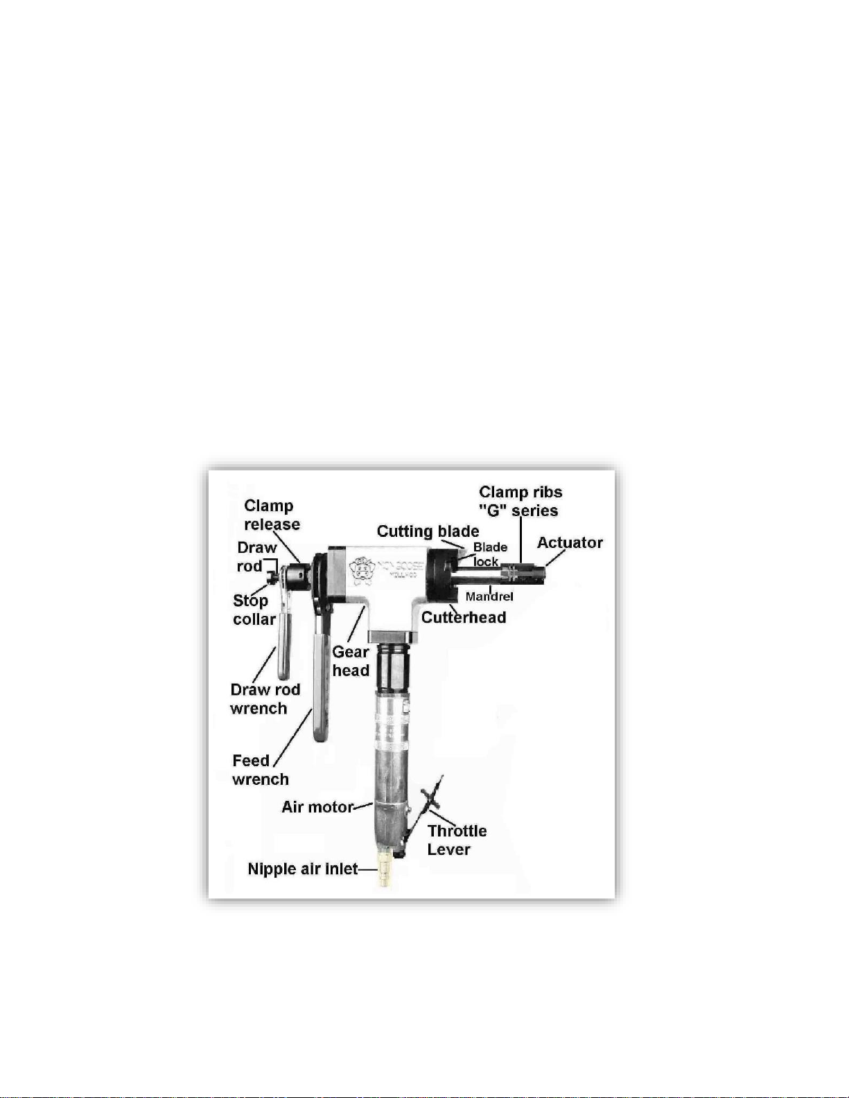
Illustrated description of function
Mongoose with standard motor
ESCO Tool Company, a Unit of ESCO Technologies, Inc. 4
Holliston, MA - USA | Tel 508.429.4441
Page 5
Operating Instructions Revision: MON-001
Millhog Series - “Mongoose” Millhog
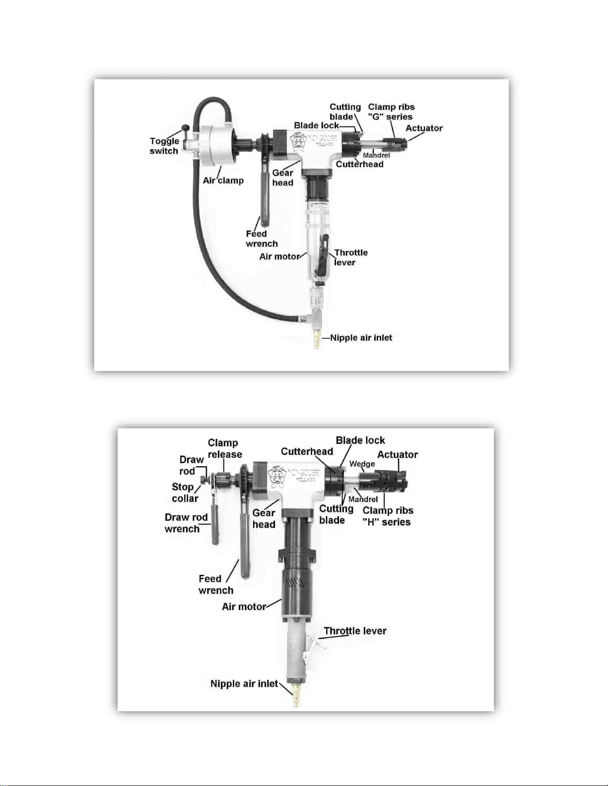
Mongoose air clamp
Mongoose SS (slow speed)
ESCO Tool Company, a Unit of ESCO Technologies, Inc. 5
Holliston, MA - USA | Tel 508.429.4441
Page 6

Operating Instructions Revision: MON-001
Millhog Series - “Mongoose” Millhog
Limitation on ambient conditions
1. In damp, moist or humid air, extra precaution must be taken in order to provide the tool with moisture
free, oil laden air.
2. In temperatures below 32 degrees Fahrenheit (0 Celsius) a lubricant with antifreeze, such as Marvel Air-
Tool Oil, must be used.
3. Do not use the electric motor in wet or excessively humid ambient conditions
List of contents
Kit contains:
Mongoose
Motor gear drive assembly
Draw rod assembly
Mandrel, ¾” or 5/8”
Hose, 1/2” w/ filter
Carrying case
Allen wrench
Operating instructions
One or more clamp rib sets
One or more cutterheads
Mongoose Air Clamp
Motor gear drive assembly
Air clamp and draw rod assembly
Mandrel, ¾” or 5/8”
Hose, 1/2” w/ filter
Carrying case
Allen wrench
Operating instructions
One or more clamp rib sets
One or more cutterheads
Mongoose SS (slow speed)
Motor gear drive assembly
Draw rod assembly
Mandrel, ¾”
Hose, 1/2” w/ filter
Carrying case
Allen wrench
Operating instructions
One or more clamp rib sets
One or more cutterheads
ESCO Tool Company, a Unit of ESCO Technologies, Inc. 6
Holliston, MA - USA | Tel 508.429.4441
Page 7

Operating Instructions Revision: MON-001
Millhog Series - “Mongoose” Millhog
Safety precautions
Precautions and use of personal protective equipment, eye protection
1. Power tools are not insulated for coming into contact with electric power sources.
2. Tool must not be used in an explosive atmosphere.
3. Do not use tool in a manner other than stated. Use other than stated in the instructions is forbidden.
4. For air powered tools, use valved, quick connect couplers to avoid an unrestrained compressed air hose
after disconnecting.
5. Use care regarding the drawing in or trapping long hair, loose clothing, etc.
6. Cover all exposed skin before operating. Cutting blades are sharp and produce hot chips. Both can cause
injury.
7. Do not connect power source until tool is securely fastened to the pipe or tube.
8. Use caution when handling, disconnect power source before removing from work, changing blades,
performing maintenance or breaking down.
9. Personal protective garments should include but not be limited to.
a. Safety glasses
b. Work gloves
c. Work boots, or shoes
d. Protective clothing
e. Hearing protection when operator is exposed to long periods of use.
10. Have all nearby persons wear safety glasses with side shields.
Special safety precautions, pinch points
1. Chips can be hot and sharp. Be careful when clearing from tool.
2. Moving and stationary parts can pinch or cause serious injury. Pay extra attention to rotating cutting
blades as they cannot be adequately guarded.
3. During use, machinery may separate, lurch or fall.
ESCO Tool Company, a Unit of ESCO Technologies, Inc. 7
Holliston, MA - USA | Tel 508.429.4441
Page 8

Operating Instructions Revision: MON-001
Millhog Series - “Mongoose” Millhog
Explanation of symbols
Caution (refer to accompanying documents).
Safety glasses must be worn.
Protective gloves, cutting blades and chips can be hot and sharp.
Work boots, or shoes
Protective clothing
Hearing protection
Pinch points
Disclaimer
1. If the equipment is used in a manner not specified by ESCO Tool, the protection provided by the
equipment may be impaired.
Operating ergonomics
1. Tool must be mounted at a reasonable working height.
2. Tool may be used in any orientation.
3. Operator must be in a position not to be injured as the machinery may separate, lurch or fall. Operator
must have both feet on a stable platform. Reaching or leaning is not acceptable operating ergonomics.
ESCO Tool Company, a Unit of ESCO Technologies, Inc. 8
Holliston, MA - USA | Tel 508.429.4441
Page 9

Operating Instructions Revision: MON-001
Millhog Series - “Mongoose” Millhog
Operating instructions
Identification of operating controls and their use
(All tools have similar m a n n e r controls except a s no ted.)
Feed wrench
Used to advance and retract the cutting blade
from the work.
Draw rod wrench
Actuates the clamping mechanism.
Actuator
Holds and aligns the clamp ribs and pads with
mandrel.
Cutterhead
Rotates and holds the cutting blades.
Three sizes available (2-1/4”, 2-1/2” and 3”)
Throttle lever
Locking throttle lever requires deliberate
action by the operator to activate the tool.
Actuating lever starts tool.
Release of lever stops tool.
Nipple air inlet
Accepts valved quick connect coupler for
connecting air supply.
Always disconnect air supply before installing,
changing or securing blades, adjusting, moving,
or breaking down.
Cutting blade
Consumable item, available in many sizes and
configurations.
Purpose: to machine end preparations on tube
or pipe.
Blade lock
Hold cutting blade to cutterhead.
Clamp ribs
Secures tool to tube or pipe inside diameter
Available in many sizes, see accompanying
clamp rib chart.
Actuator
Connects the clamp ribs to the draw rod.
Mandrel
Two sizes available 5/8” & ¾”
Provides torque acceptance for entire tool.
Allows axial movement of tool.
Provides point of rotation for cutterhead.
Air clamp
Actuates the clamping mechanism
Toggle switch
Actuates the air clamp
Wedge
for use with H series clamp ribs and pads on ¾”
mandrel
Selection of proper tooling
Clamp rib selection
1. Measure inside diameter of tube or pipe. Or using the outside diameter and minimum wall thickness,
calculate the inside diameter.
2. Using the inside diameter and the accompanying clamp rib chart select the proper clamp rib set.
3. Please note G-4 - G-13 uses clamp rib springs while G-02A, G-03A use bands.
Cutterhead selection
1. Measure the outside diameter of the tube or pipe.
2. Select a cutterhead that either matches the outside diameter or is at least one size larger than the outside
diameter.
3. Sizes are: 2-1/4”, 2-1/2”, or 3”
a. ¾” Mandrel uses cutterheads MG-28 2-1/4”, MG-28A 2-1/2”, MG-28B 3”.
b. 5/8” Mandrel uses cutterheads MG-28C 2-1/4”.
4. Larger cutterheads may be used, subject to mechanical restrictions.
ESCO Tool Company, a Unit of ESCO Technologies, Inc. 9
Holliston, MA - USA | Tel 508.429.4441
Page 10

Operating Instructions Revision: MON-001
Millhog Series - “Mongoose” Millhog
Cutting blade selection
1. Measure the wall thickness of the tube or pipe.
2. Select a blade that is wider than the wall thickness.
3. Standard widths are: 3/8”, 5/8”. Consult factory for other widths.
4. Cutting blade configuration should be matched to your welding specification.
5. Consult factory for special applications such as: counter boring, seal weld removal, “J” preps, etc.
Installation of proper tooling
Clamp rib installation
Mongoose and Mongoose SS
1. Remove stop collar (MG-23), using draw rod wrench (MG-22) feed the draw rod assembly from mandrel
(MG-38).
2. Slide clamp ribs over the draw rod (MG-16) with the T end of the clamp rib towards the actuator.
3. Insert the clamp rib into the slots on the actuator.
4. Inspect springs or bands, replace if stretched or damaged.
5. G2, G3 clamp ribs use a spring steel band. G4 clamp rib uses (1) spring. G5-G13 use (2) springs, H series
ribs use springs.
6. Reassemble, insert draw rod assembly into mandrel and feed it into place using the draw rod wrench. Re-
install the stop collar.
Mongoose air clamp
1. Disengage clamp ribs from actuator.
2. Unthread draw rod and remove from mandrel.
3. Slide clamp ribs off draw rod from the threaded end.
4. Slide new clamp ribs on from threaded end.
5. Insert draw rod into mandrel and thread into air cylinder.
a. Turn draw 5-8 turns complete turns to properly insert it into the air cylinder.
6. Engage clamp ribs with actuator and mandrel
Cutterhead removal and installation
Mongoose and Mongoose SS
1. Remove stop collar (MG-23), using draw rod wrench (MG-22) feed the draw rod assembly from mandrel
(MG-38).
a. If wedge is installed on mandrel it must be removed by loosening set screws and taping off with
soft hammer.
2. Remove (3) cutterhead mounting screws (MG-26).
3. Using a soft hammer, tap cutterhead to remove from bearing (MG-29).
4. Select the cutterhead you want to install and align cutterhead mounting screw holes up with the drive
shaft (MG-30).
5. Using the cutterhead mounting screws, evenly tighten. Be sure that the cutterhead seats evenly on the
bearing.
6. Insert draw rod assembly into mandrel using the draw rod wrench. Install the stop collar.
ESCO Tool Company, a Unit of ESCO Technologies, Inc. 10
Holliston, MA - USA | Tel 508.429.4441
Page 11

Operating Instructions Revision: MON-001
Millhog Series - “Mongoose” Millhog
Mongoose air clamp
1. Disengage clamp ribs from actuator.
2. Unthread draw rod and remove from mandrel.
a. If wedge is installed on mandrel it must be removed by loosening set screws and taping off with
soft hammer.
3. Remove (3) cutterhead mounting screws (MG-26).
4. Using a soft hammer, tap cutterhead to remove from bearing (MG-29).
5. Select the cutterhead you want to install and align cutterhead mounting screw holes up with the drive
shaft (MG-30).
6. Using the cutterhead mounting screws, evenly tighten. Be sure that the cutterhead seats evenly on the
bearing.
a. Insert draw rod into mandrel and thread into air cylinder. Turn draw 5-8 turns complete turns to
properly insert it into the air cylinder.
Cutting blade removal and installation
1. Loosen blade lock screw(s) (MG-24), do not remove. If more than one blade lock screw has to be loosened
they should be loosened evenly.
2. Cutting blade must be slid to the outside of the cutterhead for removal.
3. Insert new cutting blade from the outside of the cutterhead and align so that the blade fully covers the
tube or pipe wall.
4. Be sure to tighten all blade lock screws
Mounting the tool to the work
Mongoose and Mongoose SS
1. Using the feed wrench extend the mandrel all the way forward (this moves clamp ribs away from
cutterhead.
2. Retract the mandrel two turns of the feed wrench.
3. Insert the clamp rib portion of the tool into the end of tube or pipe.
4. While positioning the cutting blade away, at least 1/4” from the work, tighten the draw rod wrench.
5. Be sure cutterhead can rotate freely, without coming into contact with the tube or pipe, when first
starting tool.
Mongoose air clamp
1. With air connected turn toggle switch to the right to relax the clamps for the mandrel.
2. Insert the clamp rib portion of the tool into the end of tube or pipe.
3. While positioning the cutting blade away, at least 1/4” from the work, turn the toggle switch to the left.
4. Be sure cutterhead can rotate freely, without coming into contact with the tube or pipe, when first
starting tool.
Power connection
1. Use the hose supplied with the tool.
2. This hose has a valved quick connect coupler which will hold back all air that is in the supply hose.
a. This feature allows the air supply to be safely removed from the tool at any time.
3. Connect the air supply.
4. For electric tools, be sure to connect the tool to a properly grounded outlet and if using an extension cord,
be sure that the extension cord is properly sized for the application. Failure to properly size an extension
cord can result in personal injury and/or harm to the electric motor
ESCO Tool Company, a Unit of ESCO Technologies, Inc. 11
Holliston, MA - USA | Tel 508.429.4441
Page 12

Operating Instructions Revision: MON-001
Millhog Series - “Mongoose” Millhog
Operation of tool
1. Engage the throttle lever (or switch) this will activate the tool.
2. Using the feed wrench advance the cutting blade towards the work.
3. Use a steady constant feed creating a continuous chip.
a. Using a constant feed allows the heat generated by the cutting action to be removed by the chip.
Heat buildup is a primary failure mode for cutting tools.
b. Engaging a rotating cutting blade with the work surface without feed (rubbing), creates excessive
heat buildup.
4. When the desired end prep is accomplished, quickly reverse the feed wrench by reversing the directional
pawl, and retract the cutting blade from the work.
5. Release the throttle lever (or switch) this will stop the tool.
6. Disconnect the power supply.
7. Release the clamp wrench and remove the tool from the work.
Tool limits
Size limits
1. Minimum inside diameter is 3/4” with standard mandrel.
a. Minimum inside diameter is 5/8” with optional mandrel.
2. Maximum outside diameter is 3” (with optional wedge)
3. Maximum wall thickness, 5/8” with standard tooling.
4. Extremely thin walls may require special tooling to prevent deformation of diameter.
Material limits
1. Difficult materials may require the following to maximize blade life.
a. Lubrication such as cutting oils, soluble oils, soapy water, plain water, etc.
b. Slow the speed of air motor, using a valve on the air supply.
c. Multiple cutting blades to balance the tool.
d. Vary feed rate, often times difficult materials respond to a heavy feed.
ESCO Tool Company, a Unit of ESCO Technologies, Inc. 12
Holliston, MA - USA | Tel 508.429.4441
Page 13

Operating Instructions Revision: MON-001
Millhog Series - “Mongoose” Millhog
Maintenance and servicing
Regular cleaning and lubrication
1. Hose whip, filter and lubricator
a. Inspect filter element by removing nut from end of filter assembly.
b. If the filter is dirty or plugged replace it using filter repair kit
c. Remove filler plug from lubricator and be sure the adjusting screw is set half way between open
and closed.
d. Fill lubricator, use a light weight air tool motor oil (s.a.e. 10).
e. For electric tools, inspect the cord for damage. If any damage is noted, the cord should be
replaced.
2. Gear housing grease
a. Grease gear head after every two hundred hours of use.
b. Use grease NLGI # 2.
3. Lubrication for storage
a. Before putting the tool away, fill air inlet with a liberal amount of air tool oil and actuate motor
momentarily. This will distribute oil to internal motor parts, preventing rust build up.
b. Wipe tool down using soft cloth removing all dirt, grease, oil and chips.
c. Lightly coat tool with rust preventive.
User service
1. A qualified air tool technician can provide all service for this machine.
a. Factory service or assistance is always available, contact us at the numbers below.
b. Complete drawings and parts lists are provided in section six.
i. No special tools are required to perform complete service.
Servicing by manufacturer or agent
1. Factory service, return the tool to the Factory address listed below.
2. Agent service, if applicable return tool to the Agent listed below.
a. If unsure of Agent contact the factory.
ESCO Tool Company, a Unit of ESCO Technologies, Inc. 13
Holliston, MA - USA | Tel 508.429.4441
Page 14

Operating Instructions Revision: MON-001
Millhog Series - “Mongoose” Millhog
Clamp rib & pad selector chart
ESCO Tool Company, a Unit of ESCO Technologies, Inc. 14
Holliston, MA - USA | Tel 508.429.4441
Page 15

Operating Instructions Revision: MON-001
Millhog Series - “Mongoose” Millhog
Parts list and drawings
ESCO Tool Company, a Unit of ESCO Technologies, Inc. 15
Holliston, MA - USA | Tel 508.429.4441
Page 16

Operating Instructions Revision: MON-001
PART # DESCRIPTION PART # DESCRIPTION
MG-24 BLADE LOCK SCREW MG-39 LOCK WASHER
MG-25 BLADE LOCK 2-1/4” HEAD MG-40 LOCK NUT
MG-25A BLADE LOCK 2-1/2” HEAD MG-41 TORQUE KEY SCREW
MG-26 CUTTERHEAD SCREW MG-42 TORQUE KEY
MG-27 CUTTERHEAD SEAL MG-43 TORQUE ACCEPTER
MG-28 CUTTERHEAD 2-1/4” MG-44 THRUST BEARING
MG-28A CUTTERHEAD 2-1/2” MG-45 FEED KNOB
MG-28B CUTTERHEAD 3” MG-46 FEED KNOB O-RING SEAL
MG-29 CUTTERHEAD BEARING MG-47 THRUST WASHER
MG-30 DRIVE SHAFT MG-48 FEED RETAINER PLATE
MG-31 DRIVE SHAFT SEAL MG-49 TORQUE ACCEPTER SCREW
MG-32 DRIVEN GEAR KEY MG-50 SNAP RING
MG-33 TAPERED ROLLER BEARING MG-51 FEED WRENCH
MG-34 BEARING RACE MG-52 DRI VE GEAR
MG-35 BEARING SPACER MG-53 DRI VE GEAR BEARING
MG-36 DRIVEN GEAR MG-54 MOTOR ADAPTER PLATE
MG-37 HOUSING MG-55 MOTOR ADAPTER SCREW
MG-38 MANDREL ¾” MG-56 COMPLETE AIR MOTOR
Millhog Series - “Mongoose” Millhog
Gearhead Assembly
ESCO Tool Company, a Unit of ESCO Technologies, Inc. 16
Holliston, MA - USA | Tel 508.429.4441
Page 17

Operating Instructions Revision: MON-001
Millhog Series - “Mongoose” Millhog
Gearhead assembly
ESCO Tool Company, a Unit of ESCO Technologies, Inc. 17
Holliston, MA - USA | Tel 508.429.4441
Page 18

Operating Instructions Revision: MON-001
PART # DESCRIPTION PART # DESCRIPTION
24-100 BEARING 24-123 ROTOR
24-101 GEAR HOUSING 24-124 BOTTOM PLATE
24-102 NYLON WASHER 24-125 PIN
24-103 SPACER 24-126 PIN
24-104 PIN 24-127 ROTOR BLADES (5/SET)
24-105 BEARING 24-128 BUSHING
24-106 TOP GEAR 24-129 BEARING
24-107 TOP GEAR SPIDER 24-130 WASHER
24-108 WASHER 24-131 SCREW
24-109 BEARING 24-132 RETAINING NUT
24-110 SNAP RING 24-133 MOTOR HOUSING
24-111 GEAR HOUSING 24-134 THROTTLE LEVER
24-112 HOUSING END NUT 24-135 THROTTLE HOUSING
24-113 BEARING 24-136 MUFFLER
24-114 RETAINING RING 24-137 COMPLETE FILTER ASSY.
24-115 LOWER GEAR SPIDER 24-137A FILTER REPAIR KIT
24-116 PIN 24-138 RETAINING SCREW
24-117 BOTTOM GEAR 24-139 RUBBER GASKET
24-118 BEARING 24-140 REGULATOR
24-118A BEARING SLEEVE 24-141 SPRING
24-119 WASHER 24-142 "O" RING
24-120 BEARING 24-143 AIR FLOW VALVE
24-121 TOP PLATE 24-144 VALVE BODY
24-122 AIR MOTOR CYLINDER 24-145 RIVET
Millhog Series - “Mongoose” Millhog
Air Motor Assembly
ESCO Tool Company, a Unit of ESCO Technologies, Inc. 18
Holliston, MA - USA | Tel 508.429.4441
Page 19

Operating Instructions Revision: MON-001
Millhog Series - “Mongoose” Millhog
Air Motor Assembly
ESCO Tool Company, a Unit of ESCO Technologies, Inc. 19
Holliston, MA - USA | Tel 508.429.4441
Page 20

Operating Instructions Revision: MON-001
PART # DESCRIPTION PART # DESCRIPTION
EG-10 MOTOR ADAPTER SCREW EM-04 CABLE SLEEVE
18-02B GEAR HOUSING (EMG) EM-05 CABLE CLIP
18-03 BEARING EM-06 SELF TAP FILLISTER HEAD SCREW
18-04 GEAR SPIDER EM-07 STRAND COMPLETE
18-05 PIN EM-08 MOTOR HOUSING
18-06 BEARING EM-09 SWITCH ROD
18-07 GEAR EM-10 SWITCH DEADMAN
18-08 BEARING EM-11 BALL BEARING, 6X19X6
18-09 RETAINER RING EM-12 RUBBER BUSHING
18-10 SPACER EM-13 BAFFLE
18-11 GEAR SPIDER EM-14 BALL BEARING, 8X22X7
18-12 BEARING EM-15 2 PART MOTOR CAP
18-15 BEARING EM-16 SELF TAP FILLISTER HEAD SCREW
18-17 PIN EM-19 BEARING FLANGE
18-18 BEARING EM-24-110 ELECTRONIC UNIT, 110V
18-19 GEAR EM-24-220 ELECTRONIC UNIT, 220V
18-35 CAP SCREW EM-25 SWITCH
18-36 LOCK WASHER EM-26-110 BRUSH HOLDER, 110V
EG-01 HOUSING SCREW EM-26-220 BRUSH HOLDER, 220V
EG-02 HOUSING EM-27 CARBON BRUSH SET
EG-03 PLANET CARRIER EM-35-110 RATING PLATE
EG-04 NEEDLE ROLLER EM-35-220 RATING PLATE
EG-05 NEEDLE ROLLER & CAGE EM-66 BUTTING WASHER
EG-06 GEAR SET
EG-08 O-RING
EM-110 ELECTRIC MOTOR ONLY, 110V
EM-01-110 ARMATURE, 110V EM-220 ELECTRIC MOTOR ONLY, 220V
EM-01-220 ARMATURE, 220V EMG-105 GEAR CASE ASSEMBLY
EM-02-110 FIELD COIL, 110V EMG-110 ELEC. MOTOR & GEAR CASE, 110V
EM-02-220 FIELD COIL, 220V EMG-220 ELEC. MOTOR & GEAR CASE, 220V
EM-03-110 CABLE WITH UL-CSA-PLUG, 110V
EM-03-220 CABLE W/ PLUG, 22OV
Millhog Series - “Mongoose” Millhog
Electric motor assembly
ESCO Tool Company, a Unit of ESCO Technologies, Inc. 20
Holliston, MA - USA | Tel 508.429.4441
Page 21

Operating Instructions Revision: MON-001
Millhog Series - “Mongoose” Millhog
Electric motor assembly (CONT.)
ESCO Tool Company, a Unit of ESCO Technologies, Inc. 21
Holliston, MA - USA | Tel 508.429.4441
Page 22

Operating Instructions Revision: MON-001
PART # DESCRIPTION PART # DESCRIPTION
MG-01 ACTUATOR, ¾” MG-17A SCREW
MG-01A ACTUATOR, 5/8” MG-17B SCREW
G-02 CLAMP RIB SET, G2 MG-18 THRUST WASHER
G-03-13 CLAMP RIB SETS G3-G13 MG-19 O-RING
MG-14 ROLL PIN MG-20 DRAW ROD NUT
MG-15 CLAMP RIB SPRING G4-G13 MG-21 NUT RETAINER
MG-15A CLAMP RIB BAND G3 MG-22 DRAW ROD WRENCH
MG-15B CLAMP RIB BAND G2 MG-22A SNAP RING
MG-16 DRAW ROD MG-23 DRAW ROD STOP
MG-17 CLAMP RELEASE SLEEVE MG-23A SCREW
Millhog Series - “Mongoose” Millhog
Draw Rod Assembly
ESCO Tool Company, a Unit of ESCO Technologies, Inc. 22
Holliston, MA - USA | Tel 508.429.4441
Page 23

Operating Instructions Revision: MON-001
PART # DESCRIPTION PART # DESCRIPTION
AHG-300 NIPPLE, 1/4" x 3/8" AHW-304 SEAL
AHG-308 FILLER PLUG AHW-305 CHICAGO FITTING, 1/2"
AHG-309 FILLER PLUG "O" RING AHW-306 SAFETY PIN
AHG-310 OIL ADJUSTING VALVE ASSY. AHW-307A COMP. FILTER & LUBE ASSY.
AHG-311 VALVE GASKET AHW-308A FILTER REPAIR KIT
AHG-312 SIGHT DISK & SEAL AHW-309 HOSE BARB 1/2" x 1/2"
AHG-313 SIGHT DISK LOCK NUT AHW-310 FILTER HOUSING
AHW-301 COUPLER AHW-311 LUBRICATOR HOUSING
AHW-302 HOSE BARB, 3/8" x 1/2" AHW-312 SPRING
AHW-303 HOSE, 1/2" x 6' AH-202 COMPLETE AIR HOSE
Millhog Series - “Mongoose” Millhog
Air Hose Assembly
ESCO Tool Company, a Unit of ESCO Technologies, Inc. 23
Holliston, MA - USA | Tel 508.429.4441
Page 24

Operating Instructions Revision: MON-001
PART # DESCRIPTION PART # DESCRIPTION
GAC-01 AIR HOSE (18-1/2" LONG) GAC-14 FRONT PLATE
GAC-02 FITTING GAC-15 RETAINER RING
GAC-03 O-RING #010 GAC-16 O-RING #210
GAC-04 AIR VALVE 4 WAY W/PLUG GAC-17 BUSHING
GAC-04A BALL AND STEM GAC-18 ADAPTER / GROUND
GAC-04B 1/8 PIPE PLUG GAC-18A ADAPTER / MONGOOSE
GAC-05 SCREW 10-24 x 3/8 BHC GAC-19 SET SCREW 1/4 -20 x 1/4
GAC-06 AIR HOSE ( 6-1/2" LONG) GAC-20 SCREW 1/4-20 X 1/2 SHC
GAC-07 BACK PLATE GAC-21 DRAWROD 1/2” MANDREL, FOR GMH
GAC-08 RETAINER RING GAC-22 DRAWROD 5/8” MANDREL FOR GMH
GAC-09 CYLINDER HOUSING GAC-22A DRAWROD 5/8”,3/4” MANDREL FOR MG
GAC-09A O RING GAC-23 T-FITTING
GAC-10 O-RING #334 GAC-24 COUPLER
GAC-11 PISTON 3" GAC-25 FITTING
GAC-12 BUSHING FOR ½” MANDREL AHG-300 NIPPLE
GAC-12A BUSHING FOR 5/8” MANDREL (GMH & MG)
GAC-13 O RING 038
Millhog Series - “Mongoose” Millhog
Air clamp assembly
ESCO Tool Company, a Unit of ESCO Technologies, Inc. 24
Holliston, MA - USA | Tel 508.429.4441
Page 25

Operating Instructions Revision: MON-001
Millhog Series - “Mongoose” Millhog
ESCO Tool Company, a Unit of ESCO Technologies, Inc. 25
Holliston, MA - USA | Tel 508.429.4441
Page 26

Operating Instructions Revision: MON-001
GBB-1
BLADE 3/8" BEVEL TIN
GBB-2
BLADE, 5/8" BEVEL TIN
GBB-3
3/8" 30 DEGREE BEVEL BLADE
GBB-4
5/8" 30 DEGREE BEVEL BLADE
GBBP-1
5/8" 37-1/2 DEG+1/4" PEEL BACK
GCB-1
BLADE, 3/8" COUNTER BORE TIN
GCB-2
BLADE, 5/8" COUNTER BORE TIN
GCB10S-1
3/8" 10 DEGREE BORING BLADE
GCB10S-2
5/8" 10 DEGREE BORING BLADE
GCBS-1
3/8"STRAIGHT BORE 18 DEG TAPER
GCBS-2
3/8"STRAIGHT BORE 18 DEG TAPER
GJB-1
3/8" "J" BEVEL 22 DEG+3/16 RAD
GJB-2
5/8" "J" BEVEL 22 DEG+3/16 RAD
GLB-1
BLADE, 3/8" LAND TIN
GLB-2
BLADE, 5/8" LAND TIN
GLRB-1
3/8" FACING BLADE W/ OD RADIUS
GLRB-2
5/8" FACING BLADE W/ OD RADIUS
GRBB-1
3/8"37-1/2 DEGREE BORING BLADE
GRBB-2
5/8"37-1/2 DEGREE BORING BLADE
GRS-1
BLADE, 3/8" SHARPENING & TIN
GRS-2
BLADE, 5/8" SHARPENING TIN
GTSR-1
3/8" TUBE STUB REMOVAL BLADE
GTSR-2
5/8" TUBE STUB REMOVAL BLADE
GTSS-1
BLADE, 3/8" TUBE SEAT
GTSS-2
BLADE, 5/8" TUBE SEAT
Millhog Series - “Mongoose” Millhog
Cutting blades
ESCO Tool Company, a Unit of ESCO Technologies, Inc. 26
Holliston, MA - USA | Tel 508.429.4441
Page 27

Operating Instructions Revision: MON-001
Millhog Series - “Mongoose” Millhog
Cutting blades (CONT . )
ESCO Tool Company, a Unit of ESCO Technologies, Inc. 27
Holliston, MA - USA | Tel 508.429.4441
 Loading...