

Page 1

Operating Instructions Revision: COM-001
Factory: Agent:
ESCO Tool Company, a Unit of ESCO Technologies, Inc.
75 October Hill Road Ste A, Holliston, MA 01746 USA
Tel 508.429.4441 | Fax 508.429.2811
Email: millhog@escotool.com | Website: www.escotool.com
Millhog Series 314 “Commander”
MILLHOG SERIES: COMMANDER MILLHOG
- (Includes 48 series, 30 series & P CD-1 1 0 /2 0 series motors)
- 90 PSI (6.2 BAR) INLET PRESSURE
- 120/230V AC FOR ELECTRIC MOTO R S
DISCONNECT AIR SUPPLY BEFORE SERVICING
UNDERSTAND ALL INSTRUCTIONS BEFORE USING
ESCO Tool Company, a Unit of ESCO Technologies, Inc. 1
Holliston, MA - USA | Tel 508.429.4441
Page 2

Operating Instructions Revision: COM-001
Millhog Series 314 “Commander”
ESCO Tool Guarantee
Guarantee: The manufacturer guarantees its products to be free from defects in material or workmanship for a
period of one year from date of shipment from its factory. Said guarantee will not apply if equipment is used in
conditions of service for which it is not recommended. The manufacturer is not responsible for damage to its
products through improper use, physical damage, poor operating practice, or normal wear.
If any device is found unsatisfactory under the guarantee, the buyer must notify ESCO Tool in writing and after
receipt of shipping instructions, buyer must return it directly to ESCO Tool, 75 October Hill Road, Holliston,
Massachusetts 01746, USA, shipping charges prepaid. Such equipment will be replaced or put in satisfactory
operating condition, free of all charges except transportation. The correction of any factory defect by repair or
replacement by the manufacturer shall constitute fulfillment of all obligations to the purchaser.
Manufacturer's guarantee is void if unauthorized repairs are made to its products.
Manufacturer shall not be liable for consequential damage in case of failure to meet the conditions of any
Guarantee or Shipping Schedule, nor will claims for labor, loss of profit, repairs, or other expenses incidental to
replacement be allowed.
No other representations, guarantees or warranties, expressed or implied, are made by the manufacturer in
connection with the manufacture and sale of its equipment.
Hold Harmless Agreement
Customer agrees to defend, indemnify and hold ESCO Tool, its owners, agents, officers, and/or employees free
and harmless from and against any and all claims, liabilities, losses, costs and out of pocket expenses (including
attorneys fees) arising out of, or in connection with the ESCO Tool equipment, its use or transportation, or out
of operations conducted by customer, its agents, employees, contractors, representatives, guests or invitees,
including, but not limited to, active and/or passive negligence.
ESCO Tool Company, a Unit of ESCO Technologies, Inc. 2
Holliston, MA - USA | Tel 508.429.4441
Page 3

Operating Instructions Revision: COM-001
Millhog Series 314 “Commander”
Contents
INSTRUCTION FOR PUTTING INTO USE ................................................................................................................................... 4
UNPACKING ................................................................................................................................................................................ 4
POWER SUPPLY............................................................................................................................................................................ 4
ILLUSTRATED DESCRIPTION OF FUNCTION .......................................................................................................................................... 4
LIMITATION ON AMBIENT CONDITIONS ............................................................................................................................................. 5
LIST OF CONTENTS ........................................................................................................................................................................ 5
SAFETY PRECAUTIONS ............................................................................................................................................................ 5
PRECAUTIONS AND USE OF PERSONAL PROTECTIVE EQUIPMENT, EYE PROTECTION ..................................................................................... 5
SPECIAL SAFETY PRECAUTIONS, PINCH POINTS .................................................................................................................................... 5
EXPLANATION OF SYMBOLS ............................................................................................................................................................ 6
DISCLAIMER ................................................................................................................................................................................ 6
OPERATING ERGONOMICS ............................................................................................................................................................. 6
OPERATING INSTRUCTIONS ................................................................................................................................................... 7
IDENTIFICATION OF OPERATING CONTROLS AND THEIR USE ................................................................................................................... 7
SELECTION OF PROPER TOOLING ...................................................................................................................................................... 7
Clamp rib selection ................................................................................................................................................................ 7
Cutting blade selection .......................................................................................................................................................... 7
INSTALLATION OF PROPER TOOLING ................................................................................................................................................. 8
Clamp rib installation ............................................................................................................................................................ 8
Cutting blade removal and installation ................................................................................................................................. 8
MOUNTING THE TOOL TO THE WORK ............................................................................................................................................... 8
POWER CONNECTION.................................................................................................................................................................... 8
OPERATION OF TOOL .................................................................................................................................................................... 8
TOOL LIMITS ............................................................................................................................................................................... 9
Size limits ............................................................................................................................................................................... 9
Material limits ....................................................................................................................................................................... 9
MAINTENANCE AND SERVICING ............................................................................................................................................. 9
REGULAR CLEANING AND LUBRICATION ............................................................................................................................................. 9
USER SERVICE .............................................................................................................................................................................. 9
SERVICING BY MANUFACTURER OR AGENT ......................................................................................................................................... 9
CLAMP RIB AND PAD SELECTOR CHART ............................................................................................................................... 10
PARTS LIST AND DRAWINGS ................................................................................................................................................ 11
GEAR HEAD ASSEMBLY ................................................................................................................................................................ 12
48 SERIES AIR MOTOR ................................................................................................................................................................. 14
30 SERIES AIR MOTOR ................................................................................................................................................................. 16
PCD-110/220 ELECTRIC MOTOR ................................................................................................................................................. 18
DRAW ROD ASSEMBLY, CLAMP RIB AND PAD ASSEMBLY...................................................................................................................... 20
RIGHT ANGLE DRIVE ASSEMBLY FOR COMMANDER AND DICTATOR ....................................................................................................... 21
OFF-SET GEAR DRIVE .................................................................................................................................................................. 22
AIR HOSE.................................................................................................................................................................................. 23
STANDARD CUTTING BLADES ........................................................................................................................................................ 24
ESCO Tool Company, a Unit of ESCO Technologies, Inc. 3
Holliston, MA - USA | Tel 508.429.4441
Page 4
Operating Instructions Revision: COM-001
Millhog Series 314 “Commander”
Instruction for putting into use
Unpacking
1. Use caution when handling the tool, cutting blades are sharp.
TYPICALLY THEY ARE PROTECTED, HOWEVER, EXPOSED BLADES CAN CAUSE INJUR Y.
2. Clean any excess oil, grease or rust preventive from the surface of the tool.
Power supply
1. Recommended air pressure, 90 psi (6.2 bar)
2. Recommended air volume, 95 cfm (2690 lt/min.)
3. Clean, moisture free air is essential for trouble free operation.
4. Oil laden operating air should be used. Use a light weight air tool motor oil (s.a.e.10).
5. A hose whip with filter and lubricator is provided with each tool. Be sure air filter is clean and lubricator is
full before use. For lubricator adjustment instructions see 4a.
6. For electric motors
a. Rated Voltage 230/120v ac
b. Power input 1800 w
c. Frequency 40-60 Hz
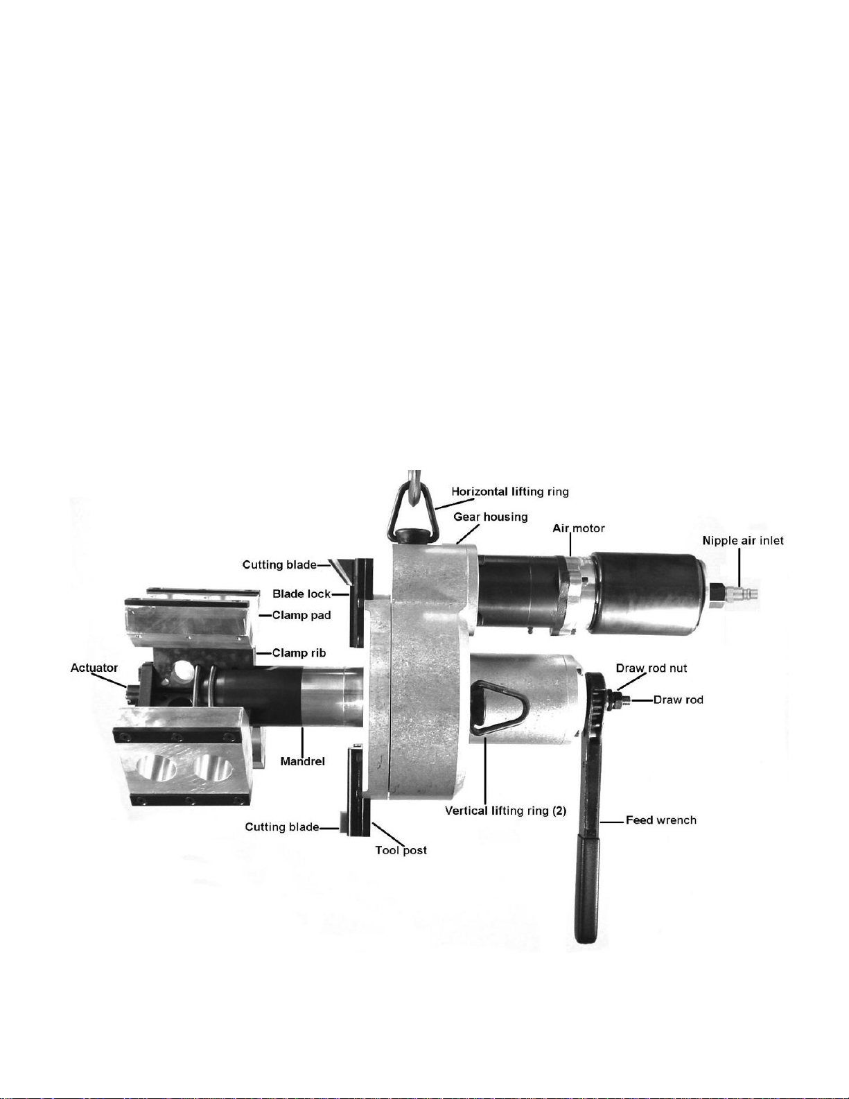
Illustrated description of function
(optional right angle dr i v e not shown)
ESCO Tool Company, a Unit of ESCO Technologies, Inc. 4
Holliston, MA - USA | Tel 508.429.4441
Page 5

Operating Instructions Revision: COM-001
Millhog Series 314 “Commander”
Limitation on ambient conditions
1. In damp, moist or humid air, extra precaution must be taken in order to provide the tool with moisture
free, oil laden air.
2. In temperatures below 32 degrees Fahrenheit (0 Celsius) a lubricant with antifreeze, such as Marvel Air-
Tool Oil , must be used.
3. Do not use the electric motor in wet or excessively humid ambient conditions
List of contents
Kit contains:
Motor and gear head
Feed mechanism
Draw rod and wrench assembly
One or more clamp rib sets
One or more clamp pad set
Hose, ¾” with filter, oiler (lubricator) and quick connect couplers, or electric cord attached to motor
Allen wrench set
Carrying case
Safety precautions
Precautions and use of personal protective equipment, eye protection
1. Do not connect the power supply until tool is securely fastened to the inside diameter of a pipe or tube.
2. Use caution when handling the tool, cutting blades are sharp. Typically they are protected, however,
exposed blades can cause injury.
3. Personal protective equipment should include, but not be limited to:
a. Safety glasses
b. Work gloves
c. Work boots, or shoes
d. Long sleeve shirts
e. Long pants
f. Ear protection should be used when operator is exposed to long periods of use.
Special safety precautions, pinch points
1. Always disconnect power supply before installing or changing cutting blades, securing to pipe or tube,
adjusting, moving, or breaking machine down.
2. Do not modify or defeat safety devices
3. Cutting blades are sharp and can cause serious injury, use caution when handling tool when blades are
installed
4. Chips can be hot and sharp. Be careful when clearing from tool.
5. Moving and stationary parts can pinch or cause serious injury. Pay extra attention to rotating cutting
blades as they can not be adequately guarded.
6. During use, machinery may separate, lurch or fall.
ESCO Tool Company, a Unit of ESCO Technologies, Inc. 5
Holliston, MA - USA | Tel 508.429.4441
Page 6

Operating Instructions Revision: COM-001
Millhog Series 314 “Commander”
Explanation of symbols
Caution (refer to accompanying documents).
Safety glasses must be worn.
Protective gloves, cutting blades and chips can be hot and sharp.
Work boots, or shoes
Protective clothing
Ear protection
Pinch points
Disclaimer
1. If the equipment is used in a manner not specified by ESCO Tool, the protection provided by the
equipment may be impaired.
Operating ergonomics
1. Tool must be mounted at a reasonable working height.
2. Tool may be used in any orientation.
3. Operator must be in a position not to be injured as the machinery may separate, lurch or fall. Operator
must have both feet on a stable platform. Reaching or leaning is not acceptable operating ergonomics.
ESCO Tool Company, a Unit of ESCO Technologies, Inc. 6
Holliston, MA - USA | Tel 508.429.4441
Page 7

Operating Instructions Revision: COM-001
Millhog Series 314 “Commander”
Operating instructions
Identification of operating controls and their use
Feed wrench
Used to advance and retract the cutting blade
from the work.
Draw rod nut
Activates draw rod and actuator.
Actuator
Holds and aligns the clamp ribs and pads with
mandrel.
Draw rod
Connects the actuator and draw rod nut.
Turning draw rod nut clockwise pulls actuator
towards mandrel and expands clamp ribs and
pads.
Turning draw rod nut counter-clockwise
pushes actuator away from mandrel and
relaxes clamp ribs and pads.
Cutterhead
Rotates and holds the tool post.
Tool post
Locates cutting blade.
Cutting blade
Purpose: to machine end preparations on tube
or pipe. b. Consumable item, available in many
sizes and configurations.
Blade lock
Secures the cutting blade to tool post.
Clamp ribs / pads
Secures tool to tube or pipe inside diameter.
Come in sets of three
Available in many sizes, see accompanying
clamp rib chart.
Mandrel
Provides torque acceptance for entire tool.
Allows axial movement of tool.
Provides point of rotation for cutterhead.
Horizontal lifting ring
For lifting tool horizontally.
Vertical lifting rings
For lifting tool vertically.
Nipple air inlet
Accepts valved quick connect coupler for
connecting air supply.
Always disconnect air supply before installing,
changing or securing cutting blades, adjusting,
moving, or breaking down.
Air motor
Provides power to gear head.
Gear head
Rotates cutterhead.
Axially moves on mandrel.
Selection of proper tooling
Clamp rib selection
1. Measure inside diameter of tube or pipe. Or using the outside diameter and minimum wall thickness,
calculate the inside diameter.
2. Using the inside diameter and the accompanying clamp rib chart select the proper clamp rib / pad set(s).
3. Please note clamp pads attach to clamp ribs. Clamp ribs can be used without clamp pads.
Cutting blade selection
1. Measure the wall thickness of the tube or pipe.
2. Select a blade that is wider than the wall thickness.
3. Standard sizes are: 1/2”, 3/4” and 1”. Consult factory for other widths.
4. Cutting blade configuration should be matched to your welding specification.
5. Consult factory for special applications such as: counter boring, compound bevels , “J” preps, etc.
ESCO Tool Company, a Unit of ESCO Technologies, Inc. 7
Holliston, MA - USA | Tel 508.429.4441
Page 8

Operating Instructions Revision: COM-001
Millhog Series 314 “Commander”
Installation of proper tooling
Clamp rib installation
1. Remove draw rod nut (C-15), and pull draw rod assembly from mandrel (C-37).
2. Slide clamp ribs over the draw rod (C-14) with the slotted end of the clamp rib towards the actuator (C-
11).
3. Insert the clamp rib slots into the slots on the actuator (C-11).
4. Inspect springs, replace if stretched or damaged.
5. There are two sets of clamp springs per set of clamp ribs.
6. Reassemble, insert draw rod assembly into mandrel and install the draw rod nut.
Cutting blade removal and installation
1. Loosen blade lock screw(s) (C-53), do not remove. If more than one blade lock screw has to loosened they
should be loosened evenly.
2. Cutting blade must be slid to the outside of the cutterhead for removal.
3. Insert new cutting blade from the outside of the cutterhead and align so that the blade fully covers the
tube or pipe wall.
4. Be sure to tighten all blade lock screws
Mounting the tool to the work
1. Using the feed wrench extend the mandrel all the way forward (this moves clamp ribs away from
cutterhead.
2. Retract the the mandrel two turns of the feed wrench.
3. Insert the clamp rib portion of the tool into the end of tube or pipe.
4. While positioning the cutting blade away, at least 1/4” from the work, tighten the draw rod wrench.
5. Be sure cutterhead can rotate freely, without coming into contact with the tube or pipe, when first
starting tool.
Power connection
1. Use the hose supplied with the tool.
2. This hose has a valved quick connect coupler which will hold back all air that is in the supply hose.
a. This feature allows the air supply to be safely removed from the tool at any time.
3. Connect the air supply.
4. For electric tools, be sure to connect the tool to a properly grounded outlet and if using an extension cord,
be sure that the extension cord is properly sized for the application. Failure to properly size an extension
cord can result in personal injury and/or harm to the electric motor
Operation of tool
1. Engage the ball valve (or switch) this will activate the tool.
2. Using the feed wrench advance the cutting blade towards the work.
3. Use a steady constant feed creating a continuous chip.
a. Using a constant feed allows the heat generated by the cutting action to be removed by the chip.
Heat build up is a primary failure mode for cutting tools.
b. Engaging a rotating cutting blade with the work surface without feed (rubbing), creates excessive
heat build up.
4. When the desired end prep is accomplished, quickly reverse the feed wrench by reversing the directional
pawl, and retract the cutting blade from the work.
5. Turn power supply off, so the motor no longer rotates the cutterhead, this will stop the tool.
6. Disconnect the power supply.
7. Release the draw rod nut and remove the tool from the work.
ESCO Tool Company, a Unit of ESCO Technologies, Inc. 8
Holliston, MA - USA | Tel 508.429.4441
Page 9

Operating Instructions Revision: COM-001
Millhog Series 314 “Commander”
Tool limits
Size limits
1. Minimum inside diameter is 3.750”.
2. Maximum outside diameter is 14”.
3. Maximum wall thickness, 1-1/4”” with standard tooling.
4. Extremely thin walls may require special tooling to prevent deformation of diameter.
Material limits
1. Difficult materials may require the following to maximize blade life.
a. Lubrication such as cutting oils, soluble oils, soapy water, plain water, etc.
b. Slow the speed of air motor, using the ball valve on the air supply.
c. Multiple cutting blades to balance the tool.
d. Vary feed rate, often times difficult materials respond to a heavy feed.
Maintenance and servicing
Regular cleaning and lubrication
1. Hose whip, filter and lubricator
a. Inspect filter element by removing nut from end of filter assembly.
b. If the filter is dirty or plugged replace it using filter repair kit
c. Remove filler plug from lubricator and be sure the adjusting screw is set half way between open
and closed.
d. Fill lubricator, use a light weight air tool motor oil (s.a.e. 10).
e. For electric tools, inspect the cord for damage. If any damage is noted, the cord should be
replaced.
2. Gear housing grease.
a. There is no grease fitting on rental tools. This is because of the tendency to over grease. Excess
grease can back up into the air motor and cause failure.
b. A single pump from a grease gun after every two hundred hours of use is sufficient for all tools
equipped with a grease fitting.
c. Use grease NLGI # 2.
3. Lubrication for storage.
a. For air powered tools, before putting the tool away, fill air inlet with a liberal amount of air tool
oil and actuate motor momentarily. This will distribute oil to internal motor parts, preventing rust
build up.
b. Wipe tool down using soft cloth removing all dirt, grease, oil and chips.
c. Lightly coat tool with rust preventive.
User service
1. A qualified tool technician can provide all service for this machine.
a. Factory service or assistance is always available, contact us at the numbers below.
b. Complete drawings and parts lists are provided in section six.
i. No special tools are required to perform complete service.
Servicing by manufacturer or agent
1. Factory service, return the tool to the factory address listed below.
2. Agent service, If applicable return tool to the agent listed below.
a. If unsure of agent contact the factory.
ESCO Tool Company, a Unit of ESCO Technologies, Inc. 9
Holliston, MA - USA | Tel 508.429.4441
Page 10

Operating Instructions Revision: COM-001
Millhog Series 314 “Commander”
Clamp rib and pad selector chart
I.D. Range (inches) I.D. Range (mm) Clamp Size
3.750” to 4.500” 95.3 to 114.3 C1 Clamp rib
4.375” to 5.250” 111.1 to 133.4 C2 Clamp rib
5.125” to 6.000 130.2 to 152.4 C3 Clamp rib
5.875” to 6.800” 149.2 to 172.7 C4 Clamp rib
6.750” to 7.562” 171.4 to 192.1 C1 Clamp rib plus C5 Clamp pad
7.437” to 8.250” 188.9 to 209.5 C2 Clamp rib plus C5 Clamp pad
8.125” to 8.938” 206.3 to 227.0 C3 Clamp rib plus C5 Clamp pad
8.875” to 9.700” 225.4 to 246.4 C4 Clamp rib plus C5 Clamp pad
9.687” to 10.500” 246.0 to 266.7 C1 Clamp rib plus C6 Clamp pad
10.375” to 11.125” 263.5 to 282.5 C2 Clamp rib plus C6 Clamp pad
11.000” to 11.812” 279.4 to 300.0 C3 Clamp rib plus C6 Clamp pad
11.750” to 12.500” 298.4 to 317.5 C4 Clamp rib plus C6 Clamp pad
12.400” to 13.250” 314.9 to 336.5 C3 Clamp rib plus C7 Clamp pad
13.125” to 14.000” 333.4 to 355.6 C4 Clamp rib plus C7 Clamp pad
ESCO Tool Company, a Unit of ESCO Technologies, Inc. 10
Holliston, MA - USA | Tel 508.429.4441
Page 11

Operating Instructions Revision: COM-001
Millhog Series 314 “Commander”
Parts list and drawings
ESCO Tool Company, a Unit of ESCO Technologies, Inc. 11
Holliston, MA - USA | Tel 508.429.4441
Page 12

Operating Instructions Revision: COM-001
PART #
DESCRIPTION
PART #
DESCRIPTION
C-16
SCREW
C-37
MANDREL
C-17
MOTOR ADAPTER PLATE
C-38
TAPERED ROLLER BEARING
C-18
SNAP RING
C-39
TAPERED BEARING RACE
C-19
SNAP RING
C-40
SCREW
C-20
BEARING
C-41
BEARING SPACER
C-21
DRIVE GEAR
C-42
SNAP RING
C-22
NEEDLE BEARING
C-43
MANDREL SUPPORT
C-23
TOOL HANGER
C-44
DRIVEN GEAR
C-24
SCREW
C-45
TAPERED BEARING RACE
C-25
HOUSING
C-46
TAPERED ROLLER BEARING
C-26
FEED KNOB
C-47
SLEEVE
C-27
SCREW
C-48
MANDREL SUPPORT
C-28
BALL RETAINER
C-49
SNAP RING
C-29
SCREW
C-50
O-RING SEAL
C-30
FEED KNOB BALL
C-51
CUTTERHEAD
C-31
SCREW
C-52
TOOL POST
C-32
FEED PLATE
C-53
BLADE LOCK SCREW
C-33
SCREW
C-54
BLADE LOCK
C-34
MANDREL THREAD
C-55
SCREW
C-35
SCREW
C-56
MANDREL WIPER
C-36
TORQUE KEY
B-28
FEED WRENCH (NOT SHOWN)
Millhog Series 314 “Commander”
Gear head assembly
ESCO Tool Company, a Unit of ESCO Technologies, Inc. 12
Holliston, MA - USA | Tel 508.429.4441
Page 13

Operating Instructions Revision: COM-001
Millhog Series 314 “Commander”
ESCO Tool Company, a Unit of ESCO Technologies, Inc. 13
Holliston, MA - USA | Tel 508.429.4441
Page 14

Operating Instructions Revision: COM-001
PART #
DESCRIPTION
PART #
DESCRIPTION
48-01
GREASE FITTING
48-20
GEAR
48-02
GEAR HOUSING
48-21
CYLINDER
48-03
GEAR CASE KEY
48-22
MOTOR PIN
48-04
BEARING
48-23
ROTOR BLADES
48-05A
DRIVE KEY
48-24
FRONT END PLATE
48-06A
FRONT GEAR SPIDER
48-25
BEARING
48-07
BEARING
48-26
RETAINER
48-08
GEAR CASE
48-27
ROTOR
48-09
PIN
48-28
LOCK WASHERS
48-10
BEARING
48-29
CAP SCREWS
48-11
GEAR
48-30
ROTOR HOUSING
48-12
GEAR SPIDER
48-31
RETAINER RING
48-13
BEARING
48-32
EXHAUST DEFLECTOR
48-14
BEVELED WASHER
48-33
GASKET
48-15
BEVELED WASHER
48-34
MOTOR END PLATE
48-16
BEARING
48-35
RETAINER RING
48-17
FRONT END PLATE
48-36
AIR STRAINER
48-18
PIN
48-37
LOCK WASHERS
48-19
BEARING
48-38
CAP SCREWS
Millhog Series 314 “Commander”
48 series air motor
ESCO Tool Company, a Unit of ESCO Technologies, Inc. 14
Holliston, MA - USA | Tel 508.429.4441
Page 15

Operating Instructions Revision: COM-001
Millhog Series 314 “Commander”
ESCO Tool Company, a Unit of ESCO Technologies, Inc. 15
Holliston, MA - USA | Tel 508.429.4441
Page 16

Operating Instructions Revision: COM-001
PART #
DESCRIPTION
PART #
DESCRIPTION
30-01
SET SCREW-M3X03
30-25
EXHAUST SHIELD
30-02
ADJUSTING NUT
30-26
RING
30-03
DRIVE SHAFT
30-28
CYLINDER HOUSING
30-04
SEAL
30-30
SPACER
30-05
BEARING
30-31
BEARING
30-06
SPACER
30-32
END PLATE
30-07
BEARING SPACER
30-33
ROTOR VANES (SET OF 5)
30-08
BEARING
30-34
ROTOR
30-09
SET SCREW-M08X008
30-35
PIN-04x014
30-10
FLANGE GEAR HOUSING
30-36
CYLINDER
30-11
PINS-05x010
30-37
END PLATE
30-12
GEAR HOUSING
30-38
BEARING
30-13
PLANETARY GEAR SPIDER
30-39
SCREW
30-14
SCREW-M06x012
30-40
PIN
30-15
PLANETARY GEAR
30-41
AIR INPUT FLANGE
30-16
BEARING
30-42
SET SCREW-M8X12
30-17
RETAINER WASHER
30-43
REAR WASHER
30-18
PINS
30-44
RETAINER FLANGE
30-19
PINS
30-45
SET SCREW-M8x12
30-21
PLANETARY GEAR
30-46
PLUG
30-22
PLANETARY GEAR SPIDER
30-23
BEARING
30-24
EXPANSION RING
30-100
COMPLETE 30 SERIES MOTOR
Millhog Series 314 “Commander”
30 series air motor
ESCO Tool Company, a Unit of ESCO Technologies, Inc. 16
Holliston, MA - USA | Tel 508.429.4441
Page 17

Operating Instructions Revision: COM-001
Millhog Series 314 “Commander”
ESCO Tool Company, a Unit of ESCO Technologies, Inc. 17
Holliston, MA - USA | Tel 508.429.4441
Page 18

Operating Instructions Revision: COM-001
Esco Part
Description
Esco Part
Description
PCD-01
ROTOR COMPLETE, 220 VOLT
PCD-40
BEARING
PCD-01A
ROTOR COMPLETE, 110 VOLT
PCD-41
NEEDLE BEARING
PCD-02
STATOR COMPLETE, 220 VOLT
PCD-42
DISK OF NEEDLE BEARING
PCD-02A
STATOR COMPLETE, 110 VOLT
PCD-43
BEARING
PCD-03
MOTOR HOUSING
PCD-44
LOCKING RING
PCD-04
AIR GUIDING RING
PCD-45
GROOVED BALL BEARING
PCD-07
CARBON BRUSH
PCD-46
DISK F. GROOVED BALL BEARG
PCD-08
DISK
PCD-47
LOCKING RING
PCD-09
SPRING DISK 34
PCD-48
INTERMEDIATE SHAFT 1
PCD-10
SCREW CM4x12
PCD-49
COUPLING WHEEL
PCD-11
BALL BEARING
PCD-50
GEAR SLEEVE
PCD-12
MAGNET RING
PCD-51
INTERMEDIATE WHEEL 1
PCD-13
BEARING SEAL
PCD-52
SPRING WASHER
PCD-14
CIRCUIT BOARD-220V
PCD-53
WASHER
PCD-14A
CIRCUIT BOARD-110V
PCD-54
WASHER
PCD-15
REVERSER
PCD-55
CLUTCH WASHER
PCD-16
SELF TAPPING SCREW
PCD-56
C-CLIP
PCD-17
MOTOR CAP
PCD-57
COUPLING, COMPLETE
PCD-18
SCREW
PCD-58
INTERMEDIATE SHAFT 2
PCD-22
CONDENSOR
PCD-59
FITTING SPRING HARDENED
PCD-23
SIDE HANDLE
PCD-60
CLUSTER GEARS
PCD-24
SWITCH
PCD-61
COUPLING BOLT
PCD-25
CONNECTION CABLE 230VOLT
PCD-62
GEAR SWITCH
PCD-25A
CONNECTION CABLE, 110V
PCD-63
INTERMEDIATE SHAFT 3
PCD-26
CABLE SLEEVE
PCD-64
INTERMEDIATE WHEEL 2
PCD-27
LOCKING FLANGE
PCD-65
WORK SPINDLE
PCD-28
SCREW 4.2x16
PCD-66
SPINDLE WHEEL
PCD-29
SCREW
PCD-67
FITTING DISK
PCD-30
SELF TAPPING SCREW
PCD-68
FITTING SPRING
PCD-31
END SHIELD
PCD-69
LOCKING RING
PCD-32
SAFETY RING 28/1.2
PCD-71
DISK SPRING
PCD-33
BEARING
PCD-72
GREASE CHAMBER
PCD-34
SAFETY RING
PCD-73
NUT, HEXAGON 8M10 x 1
PCD-35
SCREW 4.2x16
PCD-74
DISK OF NEEDLE BEARING
PCD-36
NEEDLE SLEEVE
PCD-37
SEAL
PCD-110
MOTOR, COMPLETE, 110V
PCD-38
NOTCHED PIN 5x16
PCD-220
MOTOR, COMPLETE, 220V
PCD-39
GEARBOX HOUSING
Millhog Series 314 “Commander”
PCD-110/220 electric motor
ESCO Tool Company, a Unit of ESCO Technologies, Inc. 18
Holliston, MA - USA | Tel 508.429.4441
Page 19

Operating Instructions Revision: COM-001
Millhog Series 314 “Commander”
PCD-110/220 electric mo t o r (cont.)
ESCO Tool Company, a Unit of ESCO Technologies, Inc. 19
Holliston, MA - USA | Tel 508.429.4441
Page 20

Operating Instructions Revision: COM-001
PART #
DESCRIPTION
PART #
DESCRIPTION
C-01
CLAMP RIB SET
C-09
SCREW 5/16-18 x 1” FH
C-02
CLAMP RIB SET
C-10
PAD CORNER
C-03
CLAMP RIB SET
C-11
ACTUATOR
C-04
CLAMP RIB SET
C-12
ROLL PIN
C-05
CLAMP PAD SET
C-13
RIB SPRING
C-06
CLAMP PAD SET
C-14
DRAW ROD
C-07
CLAMP PAD SET
C-15
DRAW ROD NUT
C-08
SCREW ¼-20 x ¾” FH
Millhog Series 314 “Commander”
Draw rod assembly, clamp rib and pad assembly
ESCO Tool Company, a Unit of ESCO Technologies, Inc. 20
Holliston, MA - USA | Tel 508.429.4441
Page 21

Operating Instructions Revision: COM-001
PART #
DESCRIPTION
PART #
DESCRIPTION
CD-1
SNAP RING
CD-8
NEEDLE BEARING
CD-2
BEARING
CD-9
HOUSING SCREWS
CD-3
DRIVE SHAFT
CD-10
BEARING
CD-4
DRIVEN BEVEL GEAR
CD-11
DRIVE GEAR
CD-5
KEY
CD-12
BEARING
CD-6
HOUSING
CD-13
SNAP RING
CD-7
HOUSING SCREW
Millhog Series 314 “Commander”
Right angle drive assembly for Commander and Dictator
ESCO Tool Company, a Unit of ESCO Technologies, Inc. 21
Holliston, MA - USA | Tel 508.429.4441
Page 22

Operating Instructions Revision: COM-001
PART #
DESCRIPTION
PART #
DESCRIPTION
CD-20
SNAP RING
CD-30
THRUST WASHER
CD-21
BEARING
CD-31
GEAR
CD-22
HOUSING
CD-32
IDLER PIN
CD-23
BUSHING
CD-33
THRUST BEARING
CD-24
THRUST WASHER
CD-34
ALIGNMENT PIN
CD-25
THRUST BEARING
CD-35
BUSHING
CD-26
NEEDLE BEARING
CD-36
BEARING
CD-27
IDLER GEAR
CD-37
HOUSING
CD-28
BALL BEARING
CD-38
SCREWS
CD-29
GEAR
CD-GB
GEAR BOX
Millhog Series 314 “Commander”
Off-set gear drive
ESCO Tool Company, a Unit of ESCO Technologies, Inc. 22
Holliston, MA - USA | Tel 508.429.4441
Page 23

Operating Instructions Revision: COM-001
PART #
DESCRIPTION
PART #
DESCRIPTION
*AHB-300
NIPPLE, 1/2"
AHB-310
THREADED COUPLER 3/4"x3/4"
AHB-301
COUPLER, 1/2" x 1/2"
AHB-311A
COMPLETE OILER
AHB-302
HOSE BARB, 3/4" x 1/2"
AHB-312
HOSE BARB, 3/4" x 3/4"
AHB-303
HOSE, 3/4" x 6'
AHB-313A
FILLER CAP
AHB-304
SEAL
AHB-314A
FEEDER ASSEMBLY
AHB-305
CHICAGO FITTING, 3/4"
AHB-315A
CHECK VALVE
AHB-306
SAFETY PIN
AHB-318A
SIGHT WINDOW
AHB-307
DIRT STOPPER ASSEMBLY
*AHB-319
THREADED COUPLER (1/2" x 1/2")
AHB-308
FILTER
*AHB-320
BALL VALVE, 1/2"
AHB-309
SCREEN
AH-204
COMP. HOSE ASSEMBLY
AHB-300,319,320 NOT INCLUDED
W/ COMPLETE HOSE ASSEMBLY
Millhog Series 314 “Commander”
Air hose
ESCO Tool Company, a Unit of ESCO Technologies, Inc. 23
Holliston, MA - USA | Tel 508.429.4441
Page 24

Operating Instructions Revision: COM-001
MBB-1
BLADE 1/2" BEVEL TIN
MBB-2
BLADE 3/4" BEVEL TIN
MBB-3
BLADE 1" BEVEL TIN
MBBP-1
1/2" 37-1/2 DEG 1/4" PEEL BACK
MBBP-2
3/4" 37-1/2 DEG 1/4" PEEL BACK
MBBP-3
1" 37-1/2 DEG ¼" PEEL BACK
MCB-1
BLADE,CUSTOM 1/2"CNTR BORE TiN
MCB-2
BLADE,CUSTOM 3/4"CNTR BORE TiN
MCB-3
BLADE,CUSTOM 1"CNTR BORE TiN
MCB10L-1
1/2" 10 DEG BORING >1-3/4"ID
MCB10L-2
3/4" 10 DEG BORING >1-3/4"ID
MCB10L-3
1" 10 DEG BORING > 1-3/4" ID
MCB10S-1
1/2" 10 DEG BORING <1-3/4 ID
MCB10S-2
3/4" 10 DEG BORING <1-3/4 ID
MCB10S-3
1" 10 DEG BORING < 1-3/4" ID
MCBSL-1
1/2" WIDE 3/8"STRAIGHT BORE 18 DEG TAPER
MCBSL-2
3/4" WIDE 3/8"STRAIGHT BORE 18 DEG TAPER
MCBSL-3
1" WIDE 3/8"STRAIGHT BORE 18 DEG TAPER
MCBSS-1
1/2" WIDE 3/8"STRAIGHT BORE 18 DEG TAPER
MCBSS-2
3/4" WIDE 3/8"STRAIGHT BORE 18 DEG TAPER
MCBSS-3
1" WIDE 3/8"STRAIGHT BORE 18 DEG TAPER
MJB-1
1/2" "J" BEVEL 22 DEG+3/16 RADIUS
MJB-2
3/4" "J" BEVEL 22 DEG+3/16 RADIUS
MJB-3
1" "J" BEVEL 22 DEG+3/16 RADIUS
MLB-1
BLADE 1/2" LAND TIN
MLB-2
BLADE 3/4" LAND TIN
MLB-3
BLADE 1" LAND TIN
MLRB-1
1/2" FACING BLADE W/ OD RADIUS
MLRB-2
3/4" FACING BLADE W/ OD RADIUS
MLRB-3
1" FACING BLADE W/ OD RADIUS
MRBB-1
1/2"37-1/2 DEGREE BORING BLADE
MRBB-2
3/4"37-1/2 DEGREE BORING BLADE
MRBB-3
1" 37-1/2 DEGREE BORING BLADE
MTSR-1
BLADE, 1/2" TUBE STUB REMOVAL
MTSR-2
BLADE, 3/4" TUBE STUB REMOVAL
MTSR-3
BLADE, 1" TUBE STUB REMOVAL
MTSS-1
BLADE, 1/2" TUBE SEAT
MTSS-2
BLADE, 3/4" TUBE SEAT
MTSS-3
BLADE, 1" TUBE SEAT
Millhog Series 314 “Commander”
Standard cutting blades
ESCO Tool Company, a Unit of ESCO Technologies, Inc. 24
Holliston, MA - USA | Tel 508.429.4441
Page 25

Operating Instructions Revision: COM-001
Millhog Series 314 “Commander”
Standa rd cutting blade s (cont.)
ESCO Tool Company, a Unit of ESCO Technologies, Inc. 25
Holliston, MA - USA | Tel 508.429.4441
 Loading...