

ESCO Technologies ETS-Lindgren EMControl 7006-001 User Manual

Model 7006-001
EMControl™
Positioner Controller Plug-In Card
User Manual

ii
ets-lindgren.com
ETS-Lindgren Inc. reserves the right to make changes to any product described herein in
Revision
Description
Date
A
Initial Release
May, 2014
B
Updated EMCenter models
June, 2014
C
Updated commands
September, 2015
order to improve function, design, or for any other reason. Nothing contained herein shall
constitute ETS-Lindgren Inc. assuming any liability whatsoever arising out of the application
or use of any product or circuit described herein. ETS-Lindgren Inc. does not convey any
license under its patent rights or the rights of others.
© Copyright 2014–2015 by ETS-Lindgren Inc. All Rights Reserved. No part of this
document may be copied by any means without written permission from
ETS-Lindgren Inc.
Trademarks used in this document: The ETS-Lindgren logo is a registered trademark, and
EMCenter, EMControl, TILE!, and EMQuest are trademarks of ETS-Lindgren Inc.
Revision Record
MANUAL, EMCONTROL | Part #399348, Rev. C

ets-lindgren.com
iii
Table of Contents
Notes, Cautions, and Warnings .............................................. vii
1.0 Introduction .......................................................................... 9
EMCenter Modular RF Platform (Required) .............................................. 10
Standard Configuration ............................................................................. 11
Optional Items .......................................................................................... 11
ETS-Lindgren Product Information Bulletin ............................................... 11
2.0 Maintenance ....................................................................... 13
Maintenance of Fiber Optics ..................................................................... 13
Service Procedures .................................................................................. 14
Contacting ETS-Lindgren .................................................................. 14
Sending a Component for Service..................................................... 14
Calibration Services and Annual Calibration...................................... 14
3.0 Specifications ..................................................................... 15
Performance Specifications ...................................................................... 15
4.0 EMControl Plug-In Card Installation ................................ 17
Plug-In Card Installation ............................................................................ 17
5.0 Operation ............................................................................ 19
EMControl Connectors and Indicators ....................................................... 19
Device 1 / Device 2 ........................................................................... 19
AUX .................................................................................................. 20
Connecting Devices to EMControl ............................................................ 20
Device 1 / Device 2: Towers and Turntables ..................................... 20
AUX: Additional Devices ................................................................... 20
Powering On and Off EMCenter ................................................................ 20
Power On .......................................................................................... 21
Power Off .......................................................................................... 22
Manual Control of EMControl .................................................................... 23
Initiate Movement.............................................................................. 24
Seek to A Specific Position for Connected Tower/Turntable .............. 25
Stop Movement ................................................................................. 25
Initiate Movement Between Upper and Lower Limit ........................... 25
Change Current Position ................................................................... 26

iv
ets-lindgren.com
Change Speed .................................................................................. 26
Control Auxiliary Devices .................................................................. 27
Change Other Settings...................................................................... 27
Define Speed Presets ....................................................................... 29
Set Up Devices ................................................................................. 30
6.0 EMControl Command Set ................................................. 33
Detailed Description of Remote Commands .............................................. 34
Detailed Command List ............................................................................. 35
ACC .................................................................................................. 35
ACC? ................................................................................................ 35
AUX# ................................................................................................ 36
AUX#? .............................................................................................. 36
CAL .................................................................................................. 37
CAL? ................................................................................................ 37
CC .................................................................................................... 38
CL ..................................................................................................... 39
CL? ................................................................................................... 39
CP .................................................................................................... 40
CP? .................................................................................................. 41
CW ................................................................................................... 41
CY .................................................................................................... 42
CY? .................................................................................................. 42
DIR? ................................................................................................. 43
DN .................................................................................................... 43
ERE .................................................................................................. 44
ERE? ................................................................................................ 45
ERR? ................................................................................................ 46
LH ..................................................................................................... 48
LH? ................................................................................................... 48
LL ..................................................................................................... 49
LL? ................................................................................................... 50
LV ..................................................................................................... 51
LV? ................................................................................................... 51
MBSND............................................................................................. 52
MBSND? ........................................................................................... 52
PARM:BCT ....................................................................................... 53

ets-lindgren.com
v
PARM:BCT? ................................................................ ..................... 53
PARM:LIMST .................................................................................... 54
PARM:LIMST? .................................................................................. 54
PARM:QKST..................................................................................... 55
PARM:QKST? ................................................................................... 55
PH .................................................................................................... 56
PV..................................................................................................... 56
P? ..................................................................................................... 57
S# ..................................................................................................... 58
S? ..................................................................................................... 58
SC .................................................................................................... 59
SC? .................................................................................................. 59
SEP .................................................................................................. 60
SEP? ................................................................................................ 60
SK..................................................................................................... 61
SKN .................................................................................................. 62
SKP .................................................................................................. 63
SKR .................................................................................................. 64
SPEED ............................................................................................. 65
SPEED? ........................................................................................... 65
SS# ................................................................................................... 66
SS#? ................................................................................................. 67
ST ..................................................................................................... 67
TT ..................................................................................................... 68
TWR ................................................................................................. 69
TYP? ................................................................................................ 70
UH .................................................................................................... 71
UH? .................................................................................................. 71
UL ..................................................................................................... 72
UL? ................................................................................................... 73
UP .................................................................................................... 73
UV .................................................................................................... 74
UV? .................................................................................................. 74
VS? ................................................................................................... 75
WL .................................................................................................... 75
WL? .................................................................................................. 76

vi
ets-lindgren.com
ZERO ............................................................................................... 77
ZERO?.............................................................................................. 77
IEEE 488.2 Mandatory Instruction Set ...................................................... 78
*CLS ................................................................................................. 78
*ESE ................................................................................................. 79
*ESE? ............................................................................................... 80
*IDN? ................................................................................................ 81
*OPC? .............................................................................................. 82
*RST ................................................................................................. 82
*SRE ................................................................................................. 83
*SRE? ............................................................................................... 84
*STB? ............................................................................................... 85
*WAI ................................................................................................. 86
Error Codes .............................................................................................. 87
Appendix A: Warranty ............................................................. 89
Duration of Warranties for EMControl Plug-In Card ................................... 89
Appendix B: EC Declaration of Conformity .......................... 91

ets-lindgren.com
vii
Notes, Cautions, and Warnings
Note: Denotes helpful information intended to provide tips for better
use of the product.
Caution: Denotes a hazard. Failure to follow instructions
could result in minor personal injury and/or property
damage. Included text gives proper procedures.
Warning: Denotes a hazard. Failure to follow instructions
could result in SEVERE personal injury and/or property
damage. Included text gives proper procedures.
Note: See the ETS-Lindgren Product Information Bulletin for safety,
regulatory, and other product marking information.
viii

ets-lindgren.com
This page intentionally left blank.
ets-lindgren.com
Introduction
9
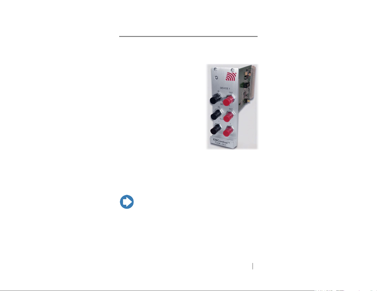
The ETS-Lindgren EMControl™
Positioner Controller Plug-in Card is a
versatile positioner controller which enables
you to synchronize the simultaneous
movements of up to two ETS-Lindgren
positioning devices (for example, towers or
turntables) and the on/off operation of an
additional auxiliary device, such as a LISN
or EUT.
EMControl allows a target location to be
entered manually or under software control
to redirect the device from its current
location to another position. EMControl
incorporates advanced acceleration and
deceleration algorithms to accurately
control variable, high speed drives.
Multiple EMControl cards can be utilized for
applications with more than two positioning
devices.
Note: EMControl is fully compatible with ETS-Lindgren towers and
turntables manufactured in 2005 and later. Contact ETS-Lindgren
for additional information.
1.0 Introduction
EMControl is designed for use with the EMCenter™ Modular RF Platform; for
more information about EMCenter, see page 10.
10
Introduction
ets-lindgren.com
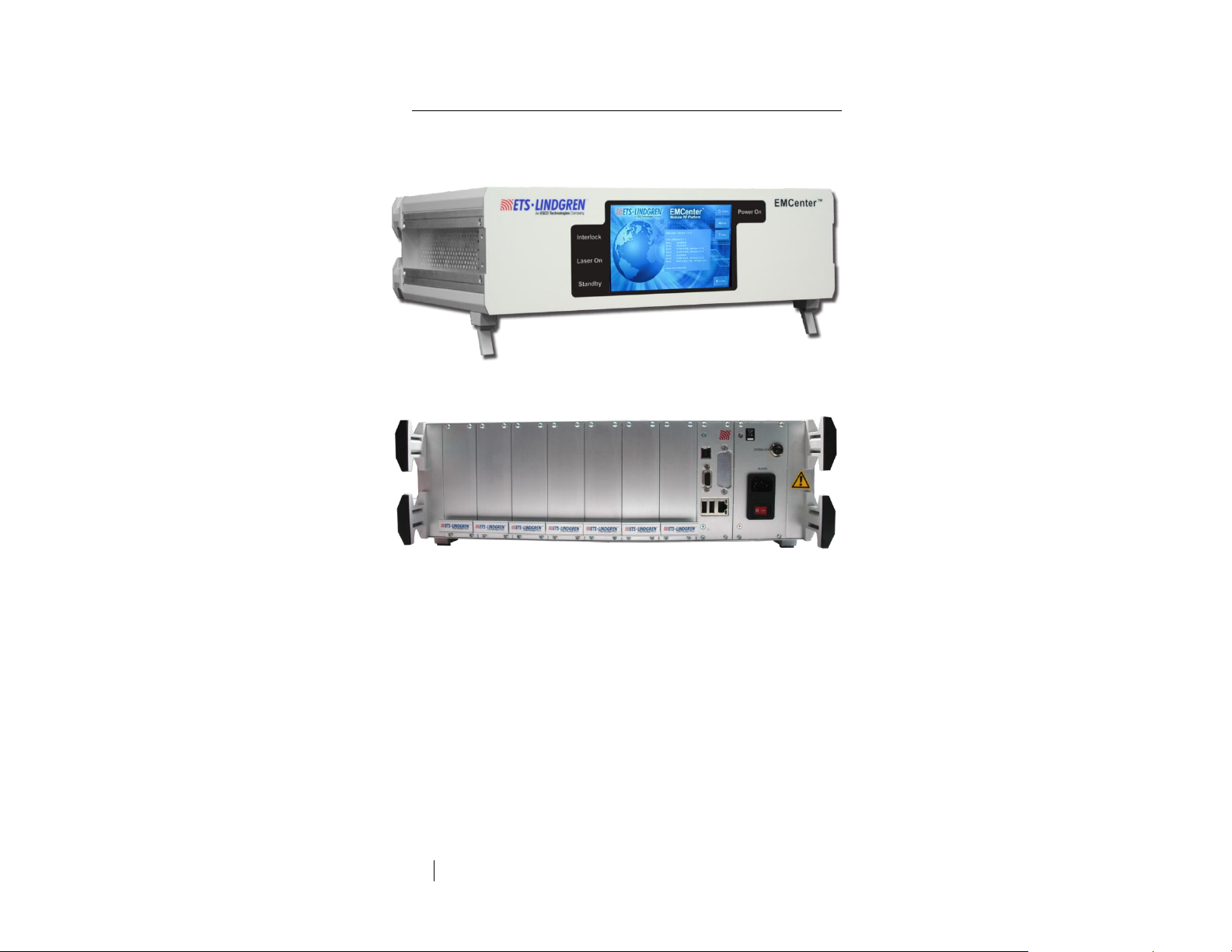
EMCenter Modular RF Platform (Required)
The EMCenter Modular RF Platform is required for operation, and is sold
separately.
Front Panel
Back Panel
The EMCenter may be controlled from a computer using these
software products:
ETS-Lindgren TILE!™ (Totally Integrated Laboratory Environment)
ETS-Lindgren EMQuest™ Data Acquisition and Analysis Software
Other test automation software
Contact ETS-Lindgren for ordering information.

ets-lindgren.com
Introduction
11
Standard Configuration
EMControl Positioner Controller Plug-in Card
Optional Items
Fiber optic cable
ETS-Lindgren Product Information Bulletin
See the ETS-Lindgren Product Information Bulletin included with your shipment
for the following:
Warranty information
Safety, regulatory, and other product marking information
Steps to receive your shipment
Steps to return a component for service
ETS-Lindgren calibration service
ETS-Lindgren contact information

12
Introduction
ets-lindgren.com
This page intentionally left blank.

ets-lindgren.com
Maintenance
13
2.0 Maintenance
CAUTION: Before performing any maintenance, follow the
safety information in the ETS-Lindgren
Product Information Bulletin included with your shipment.
WARNING: Maintenance of the EMControl card is limited
to external components such as cables or connectors.
If you have any questions concerning
maintenance, contact ETS-Lindgren
Customer Service.
WARRANTY
Maintenance of Fiber Optics
The fiber optic cables and connectors used with EMControl™ Positioner
Controller Plug-in Card can be damaged from airborne particles, humidity and
moisture, oils from the human body, and debris from the connectors they plug
into. Always handle connectors and cables with care.
Fiber optic cables and connectors are easily broken if twisted or bent. Make sure
the fiber optic cabling does not hang unsupported from where it connects to the
EMControl card. Keep the cables as straight as possible from the connector to
the protective sheath.
Following are additional guidelines to protect fiber optic cables.

14
Maintenance
ets-lindgren.com
CAUTION: Before performing any maintenance,
disconnect the fiber optic cables from the unit and turn off
power.
When disconnecting fiber optic cables, apply the included
dust caps to the ends to maintain their integrity.
Before connecting fiber optic cables, clean the connector
tips and in-line connectors.
Before attaching in-line connectors, clean them with
moisture-free compressed air.
Failure to perform these tasks may result in damage to the
fiber optic connectors or cables.
Note: Please see www.ets-lindgren.com for a list of ETS-Lindgren
offices, including phone and email contact information.
Service Procedures
CONTACTING ETS-LINDGREN
SENDING A COMPONENT FOR SERVICE
For the steps to return a system or system component to ETS-Lindgren for
service, see the Product Information Bulletin included with your shipment.
CALIBRATION SERVICES AND ANNUAL CALIBRATION
See the Product Information Bulletin included with your shipment for information
on ETS-Lindgren calibration services.
ets-lindgren.com
Specifications
15
3.0 Specifications
Note: For complete operating specifications, see the EMCenter
Modular RF Platform User Manual.
Linear Resolution:
0.1 cm
Rotation Resolution:
0.1º
Form Factor:
Occupies one slot of EMCenter
Fiber Optic I/O:
Device 1: In (1), Out (1)
Device 2: In (1), Out (1)
Auxiliary (2)
Performance Specifications

16
Specifications
ets-lindgren.com
This page intentionally left blank.

ets-lindgren.com
EMControl Plug-In Card Installation
17
4.0 EMControl Plug-In Card Installation
CAUTION: : Before connecting any components, follow
the information in the ETS-Lindgren Product Information
Bulletin included with your shipment.
Caution: The EMControl card is designed to be used
ONLY with the EMCenter. Do not use the card in
combination with any other system.
Plug-In Card Installation
1. Determine in which empty slot in the EMCenter™ Modular RF Platform
you want to install the EMControl™ Positioner Controller Plug-in Card.
Looking at the back of the EMCenter, the slots are numbered
1 through 7 from left to right.
2. Remove the blank panel from the slot by removing the two screws at
the top of the blank panel and the two screws at the bottom.
3. Carefully insert the EMControl card into the slot of the EMCenter.
Tighten the four screws.
4. Turn on the EMCenter. The EMCenter will automatically detect the
newly-installed EMControl card.
5. Depending on the test setup requirements, connect coaxial cables to
the relay connections on the back panel of the EMCenter.
6. Connect the EMCenter to a personal computer using USB, RS-232,
Ethernet, or IEEE (optional).
7. Plug the interlock into the connector on the back of the EMCenter.
The card installation is complete. You can control EMControl through the
EMCenter touchscreen, with ETS-Lindgren TILE!™ (Totally Integrated
Laboratory Environment), ETS-Lindgren EMQuest™ Data Acquisition and
Analysis Software, and other test automation software packages. Contact
ETS-Lindgren for additional information.

18
EMControl Plug-In Card Installation
ets-lindgren.com
This page intentionally left blank.
ets-lindgren.com
Operation
19
5.0 Operation
CAUTION: Before placing into operation, follow the safety
information in the ETS-Lindgren Product Information
Bulletin included with your shipment.
CAUTION: Prior to operation, verify that the mains voltage
is within the operating range of the equipment.
Note: For information on connecting devices to EMControl, see the
next section on page 20.
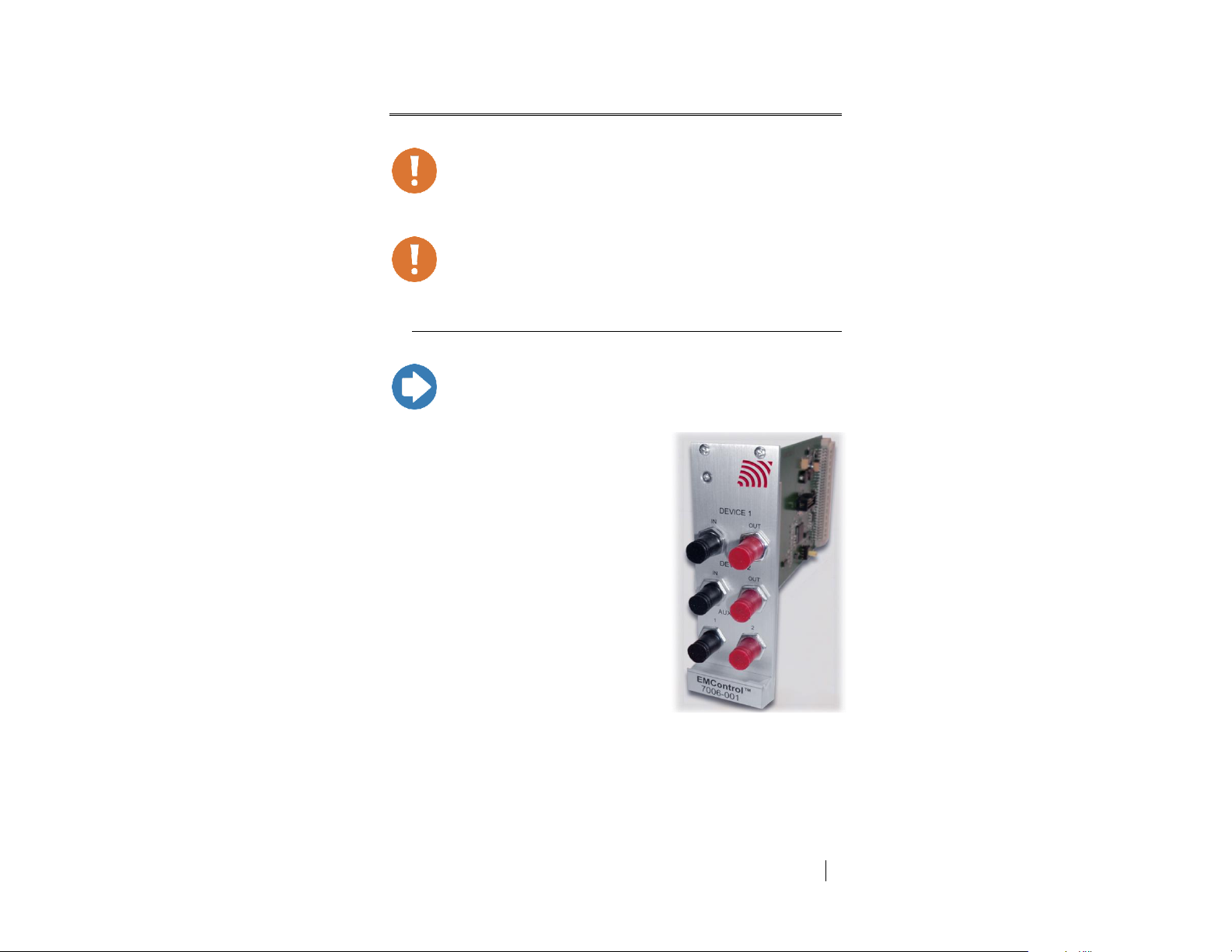
DEVICE 1 / DEVICE 2
The EMControl™ Positioner Controller
Plug-in Card provides IN and OUT ports for
connecting any combination of towers and
turntables, up to two devices.
Use DEVICE 1 to connect a tower.
Use DEVICE 2 to connect a
turntable.
EMControl Connectors and Indicators

20
Operation
ets-lindgren.com
AUX
Note: For information on using the EMCenter touchscreen, see the
EMCenter Modular Test System User Manual.
EMControl provides two ports for connecting additional devices, such as LISNs
(Line Impedance Stabilization Network) and EUTs (Equipment Under Test). They
may be connected in any combination, up to two devices.
Use AUX 1 and AUX 2 to connect an additional device.
Connecting Devices to EMControl
DEVICE 1 / DEVICE 2: TOWERS AND TURNTABLES
To connect a tower or turntable to EMControl, use the dual fiber optic cable
included with the device. The dual fiber optic cable provides two ST connectors
at each end; either end can be connected to EMControl.
1. Plug an ST connector at one end of the fiber optic cable to the IN port
of the device, and plug the ST connector at the other end to the
OUT port on the EMControl card.
2. Plug the remaining ST connector at one end of the fiber optic cable to
the OUT port of the device, and plug the remaining ST connector at the
other end to the IN port on the EMControl card.
AUX: ADDITIONAL DEVICES
Connect additional devices such as LISNs and EUTs to the AUX 1 and AUX 2
ports on the EMControl card. Use AUX 1 if connecting a single additional device.
Powering On and Off EMCenter

ets-lindgren.com
Operation
21
POWER ON
Note: If no devices are connected to EMControl, or if they are
connected improperly, dashes will display on the screen when the
power is turned on.
Note: Verify all cards are installed correctly in the EMCenter. Verify
all devices are properly connected to the EMControl card.
1. Plug the power cord from the mains inlet on the back panel of the
EMCenter into a power outlet.
2. Plug the interlock jack into the interlock connector on the back panel of
the EMCenter.
3. Turn the power switch located on the back panel of the EMCenter to
the on position.
4. Touch anywhere on the EMCenter screen. It will take approximately
20 seconds to boot. The Information screen will flash, and then the
Home screen will display.
Sample EMCenter Home Screen

22
Operation
ets-lindgren.com
POWER OFF
Note: When the EMCenter is in standby mode, touch the screen
anywhere to reboot.
1. Press the Off button located on the EMCenter screen.
2. Press OK to switch off the system.
The standby light located on the front panel of the EMCenter will flash,
and then will illuminate steadily.
3. Turn the power switch located on the back panel of the EMCenter to
the off position.
4. Remove the power cord from the power connector on the back panel
of the EMCenter.
5. Remove the interlock jack from the interlock connector on the
back panel of the EMCenter.
ets-lindgren.com
Operation
23
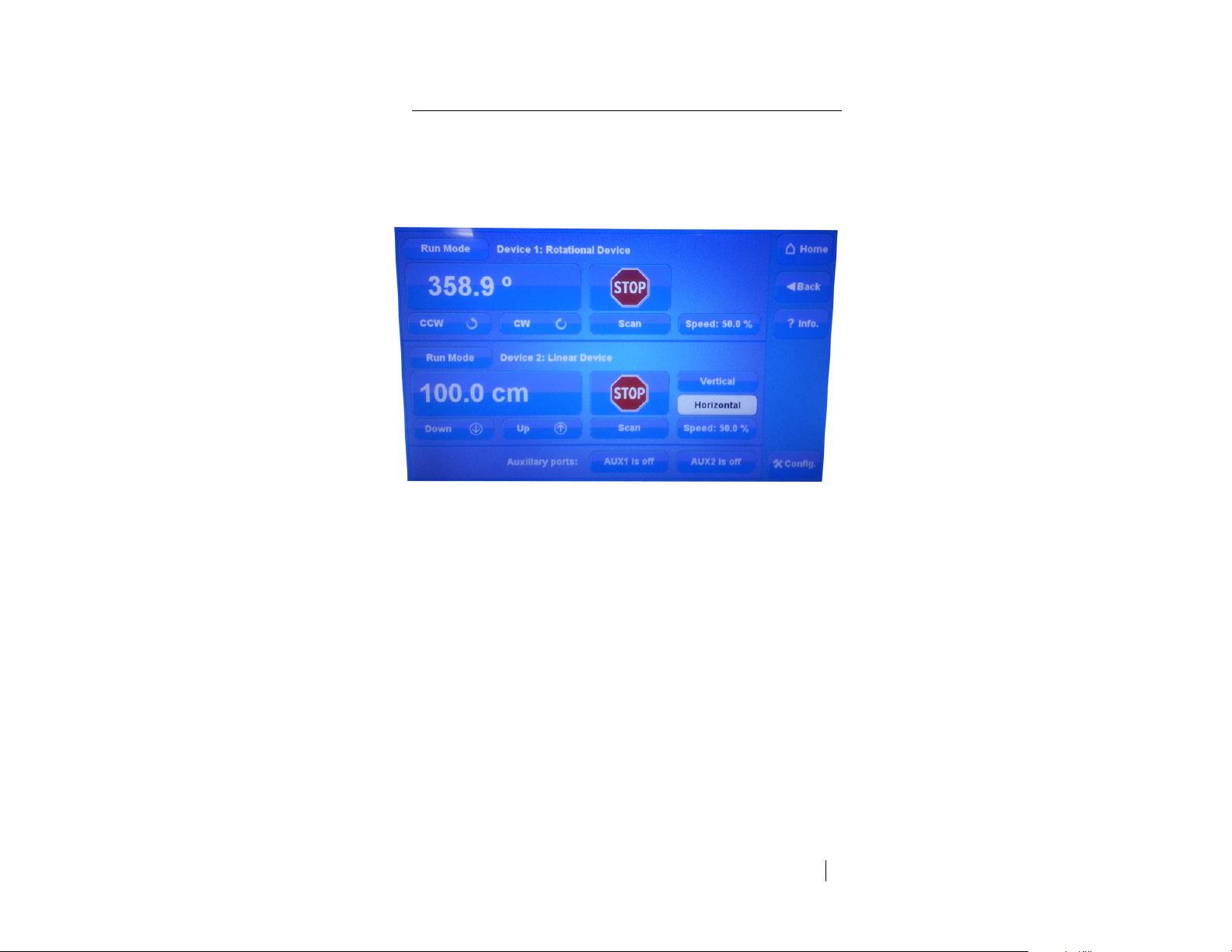
Manual Control of EMControl
To control the movement of the connected positioning equipment and change
settings, on the Home screen press the status box to the right of the slot number
for the installed EMControl plug-in card (see page 21 for a sample
Home screen). This will display the following EMControl screen:
Sample EMControl screen
Following is a description of each function you can perform from the
EMControl screen:
Initiate Movement—see page 24
Seek to a Specific Position for Connected Tower/Turntable—see
page 25
Stop Movement—see page 25
Initiate Movement Between Upper and Lower Limit—see page 25
Change Current Position—see page 26
Change Speed—see page 26
Control Auxiliary Devices—see page 27
Change Other Settings—see page 27
Define Speed Presets—see page 29
Set Up Devices—see page 30

24
Operation
ets-lindgren.com
INITIATE MOVEMENT
From the EMControl screen use the
Down button or Up button for a linear device like
an antenna mast; use the CCW button or
CW button for a rotational device like a
turntable. Depending on the mode, these
buttons will cause a different reaction. The
mode can be set to Jog, Step, or Run.
Jog mode—Movement continues as long as the
button remains pressed. Releasing the button will
stop the movement.
Step mode—Each button push will result in motion
defined by the step size. Step size is configured in
StepSize on the Configuration screen; see
Change Other Settings on page 27.
Run mode—A button push initiates movement.
Movement stops only when the Stop button is
pressed.
ets-lindgren.com
Operation
25
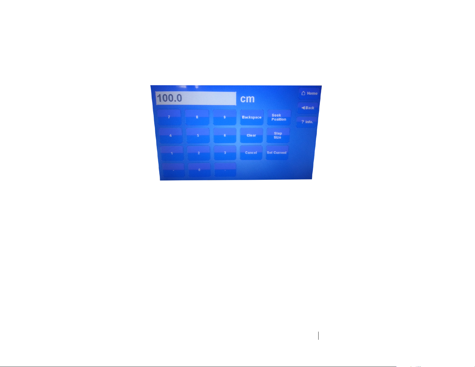
SEEK TO A SPECIFIC
POSITION FOR
CONNECTED
TOWER/TURNTABLE
From the EMControl screen press the button
displaying the current position. When the
following Settings screen displays, enter the
new number at the keypad, and then press
Seek Position to move to this position.
EMControl Settings screen
STOP MOVEMENT
From the EMControl screen press Stop.
INITIATE MOVEMENT
BETWEEN UPPER AND
LOWER LIMIT
From the EMControl screen press Scan to
initiate movement between the upper and lower
limit for the number of cycles set in the
Scan Cycle Count on the Configuration screen.
Limits are also configured in the
Configuration screen.
For information on the Configuration screen,
see page 27.
26
Operation
ets-lindgren.com
CHANGE CURRENT
POSITION
From the EMControl screen press the button
displaying the current position for the connected
turntable or tower. When the Settings screen
displays, enter the new number at the keypad,
and then press Set Current to set this value as
the current position.
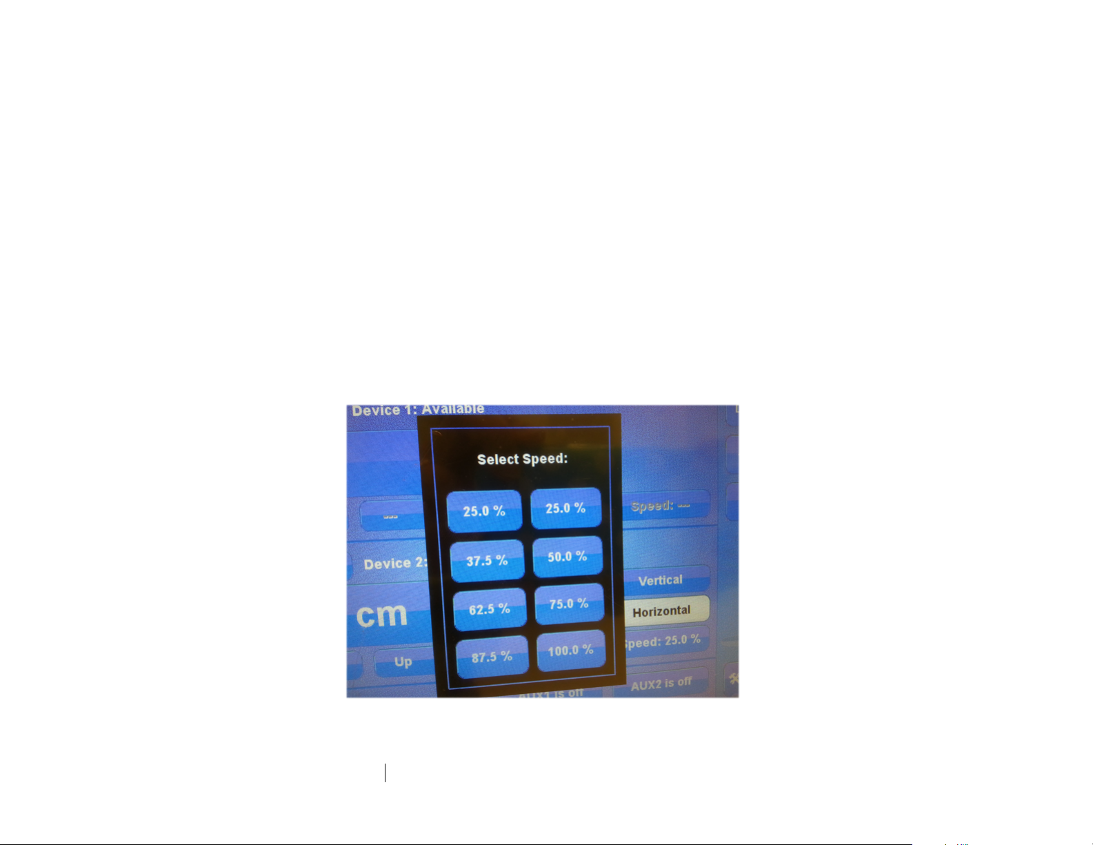
CHANGE SPEED
Speed is expressed as a percentage of
maximum speed; there are eight speeds to
choose from. To change the speed, from the
EMControl screen press Speed and then select
the required speed from the Speeds screen.
The eight preset speeds available are
configured by using the Speed Presets button in
the Configuration screen. For information on
Speed Presets, see page 29.
EMControl Speeds screen
ets-lindgren.com
Operation
27
CONTROL AUXILIARY
DEVICES
To toggle the auxiliary ports 1 and 2 between on
and off, from the EMControl screen press the
AUX1 and AUX2 buttons.
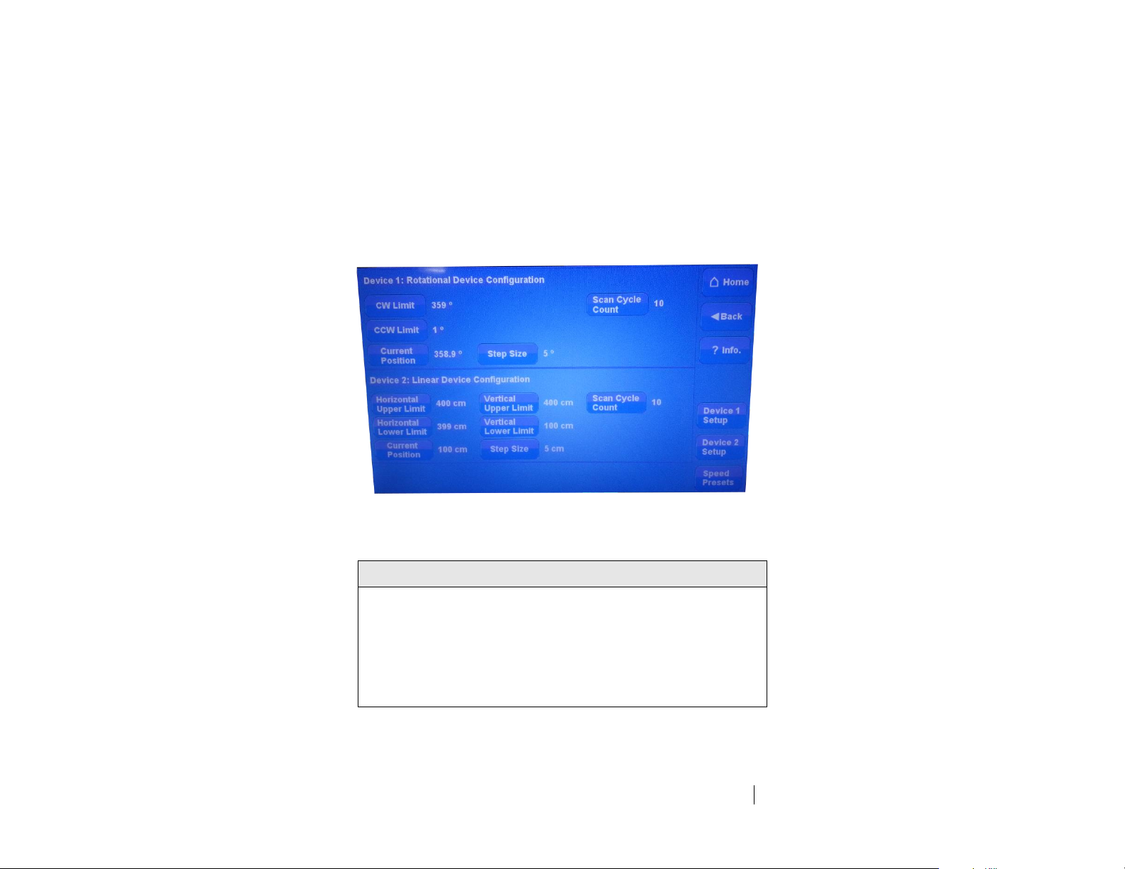
CHANGE OTHER
SETTINGS
To change other settings for the connected
positioning equipment, from the EMControl
screen press Config to display the following
Configuration screen.
EMControl Configuration screen
Upper Limit/CW Limit
Displays the current setting for the device. Upper limit is for towers and
CW limit for turntables.
To change the current setting, press Upper limit / CW Limit, enter the
new number at the keypad, and then press degr. (for turntable) or
cm (for tower).

28
Operation
ets-lindgren.com
Lower Limit/CCW Limit
Displays the current setting for the device. Lower Limit is for towers and
CCW limit is for turntables.
To change the current setting, press Lower limit/ CCW Limit, enter the
new number at the keypad, and then press degr. (for turntable) or
cm (for tower).
Current Position
Displays the current position for the device.
To change the current setting, press Current position, enter the
new number at the keypad, and then press degr. (for turntable) or
cm (for tower).
Scan Cycle Count
Displays the scan cycle count, the number of times the positioner will
move between the upper and lower limit while scanning.
To change the current setting press Scan Cycle Count, enter the new
number at the keypad and press Enter.
Step Size
Displays the step size, the number of degrees or cm the positioner will
move in Step mode.
To change the current setting press Step Size, enter the new number at
the keypad and press Enter.
 Loading...