

ESCO Technologies ETS-Lindgren 3112, ETS-Lindgren 3106B, ETS-Lindgren 3119, ETS-Lindgren 3116C, ETS-Lindgren 3115 User Manual
...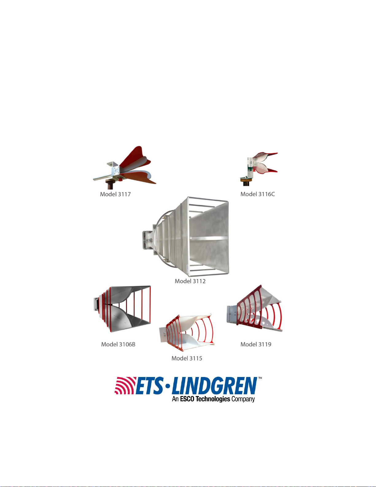
Models 3112, 3106B, 3119,
3115, 3117, 3116C
Double-Ridged Waveguide
Horn Antennas
User Manual

ETS-Lindgren Inc. Although the information in this document has been carefully reviewed and is
Revision
Description
Date
A
Initial Release
October, 2010
B
Update 3116B to 3116C. Updates to all
sections.
May , 2012
C
Updated 7-TR boom information; updated
mounting information; added 3106B on 7-TR
mounting instructions
August, 2013
D
Added optional 7/16 DIN connector to
Model 3119
March, 2014
believed to be reliable, ETS-Lindgren does not assume any liability arising out of the application
or use of any product or circuit described herein; nor does it convey any license under its patent
rights nor the rights of others. All trademarks are the property of their respective owners.
© Copyright 2010–2014 by ETS-Lindgren Inc. All Rights Reserved. No part of this
document may be copied by any means without written permission from
ETS-Lindgren Inc.
Trademarks used in this document: The ETS-Lindgren logo is a trademark of ETS-Lindgren Inc.
Revision Record
MANUAL, DOUBLE-RIDGED WAVEGUIDE HRN FAM | Part #399318, Rev. D
ii |

Table of Contents
Notes, Cautions, and Warnings ......................................................................... v
1.0 Introduction ................................................................................................... 7
Double-Ridged Waveguide Horn Antennas ....................................................................... 7
Model 3112 .................................................................................................................. 7
Model 3106B ................................................................................................................ 7
Model 3119 .................................................................................................................. 8
Model 3115 .................................................................................................................. 8
Model 3117 .................................................................................................................. 8
Model 3116C ................................................................................................................ 9
Optional Items..................................................................................................................... 9
Tripod Options .............................................................................................................. 9
7-TR Boom Options ................................................................................................... 10
Model 3112 Positioning System ................................................................................. 11
ETS-Lindgren Product Information Bulletin ...................................................................... 11
2.0 Maintenance ................................................................................................ 13
Annual Calibration ............................................................................................................ 13
Replacement and Optional Parts ..................................................................................... 13
Service Procedures .......................................................................................................... 14
3.0 Specifications .............................................................................................. 15
Electrical Specifications .................................................................................................... 15
Model 3112 ................................................................................................................ 15
Model 3106B .............................................................................................................. 15
Model 3119 ................................................................................................................ 16
Model 3115 ................................................................................................................ 16
Model 3117 ................................................................................................................ 16
Model 3116C .............................................................................................................. 17
Physical Specifications ..................................................................................................... 17
Model 3112 ................................................................................................................ 17
Model 3106B .............................................................................................................. 17
Model 3119 ................................................................................................................ 17
Model 3115 ................................................................................................................ 18
Model 3117 ................................................................................................................ 18
Model 3116C .............................................................................................................. 18
4.0 Mounting Instructions ................................................................................ 19
| iii

4-TR Mounting Instructions .............................................................................................. 19
Included Mounting Hardware ..................................................................................... 19
Attach Mounting Bracket to Antenna ......................................................................... 20
Attach Stinger Mount (Models 3117 and 3116C Only) .............................................. 21
Mount Antenna and Bracket to 4-TR ......................................................................... 22
7-TR and Mast Mounting Options..................................................................................... 23
2x2 Boom Mounting Options ............................................................................................ 24
5.0 Mounting a Model 3112 to the Optional Positioning System .................. 25
Rear Plate Mounting Pattern ............................................................................................ 25
Connecting the Optional Positioning System ................................................................... 27
Input Locations ................................................................................................................. 27
Air Polarization Option ...................................................................................................... 28
6.0 Mounting a Model 3106 Series Antenna to a 7-TR ................................... 29
7.0 Typical Data ................................................................................................. 33
Model 3112 ....................................................................................................................... 33
Model 3106B..................................................................................................................... 35
Model 3119 ....................................................................................................................... 37
Model 3115 ....................................................................................................................... 40
Model 3117 ....................................................................................................................... 43
Model 3116C .................................................................................................................... 46
Appendix A: Warranty ...................................................................................... 49
Appendix B: Typical Measured Radiated Patterns ........................................ 51
Model 3106B..................................................................................................................... 51
Model 3119 ....................................................................................................................... 56
Model 3115 ....................................................................................................................... 62
Model 3117 ....................................................................................................................... 68
iv |
Notes, Cautions, and Warnings
Note: Denotes helpful information intended to provide tips for
better use of the product.
Caution: Denotes a hazard. Failure to follow instructions
could result in minor personal injury and/or property
damage. Included text gives proper procedures.
Warning: Denotes a hazard. Failure to follow instructions
could result in SEVERE personal injury and/or property
damage. Included text gives proper procedures.
See the ETS-Lindgren Product Information Bulletin for safety, regulatory, and other
product marking information.
| v

This page intentionally left blank.
vi |

The Model 3112 Double-Ridged
Waveguide Horn is a linearly polarized
antenna covering the frequency range
of 100 MHz to 1 GHz.
The Model 3112 is especially effective
for generating high electromagnetic
fields with relatively low power input.
The antenna is also useful for receiving
low-level signals where high gain
characteristics are needed.
The Model 3106B Double-Ridged
Waveguide Horn is a linearly polarized
broadband antenna covering a
frequency range of 200 MHz to
2.5 GHz. It is precision-machined from
aluminum, making it lightweight and
durable. Two brackets are attached to
the sides of the antenna so it can be
polarized either horizontal or vertically.
1.0 Introduction
The ETS-Lindgren family of Double-Ridged Waveguide Horn Antennas
consists of linearly polarized broadband antennas ranging in frequency from
100 MHz to 40 GHz. These antennas were designed and built specifically from
EMI measurements and specifications compliance testing. However, they can
also be used for antenna gain, pattern measurement, surveillance, automotive,
and military EMC immunity applications.
Double-Ridged Waveguide Horn Antennas
MODEL 3112
MODEL 3106B
The Model 3106B has high gain and excellent VSWR characteristics over the
entire frequency range (see Appendix B on page 51 for data charts). It is
especially effective for generating high electromagnetic field with relatively low
power input. The antenna is also useful for receiving low level signals where high
gain characteristics are needed.
Introduction | 7
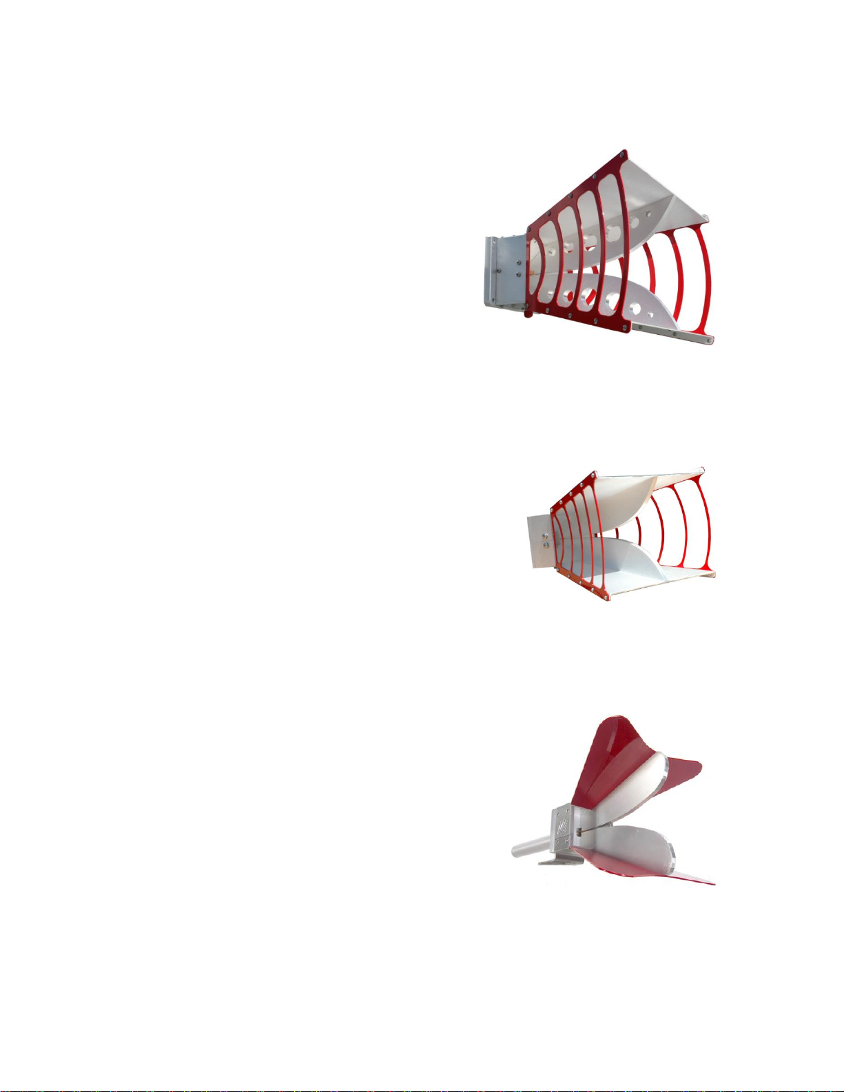
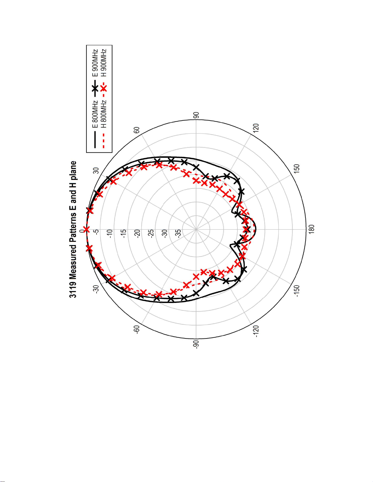
The Model 3119 Double-Ridged
Waveguide Horn is a linearly polarized
broadband antenna covering the
frequency range of 400 MHz to 6 GHz.
The Model 3119 is ideally suited for
immunity over 1 GHz and as a
reference antenna for wireless testing.
In addition, the 3119 is useful for
antenna pattern measurement as a
source antenna.
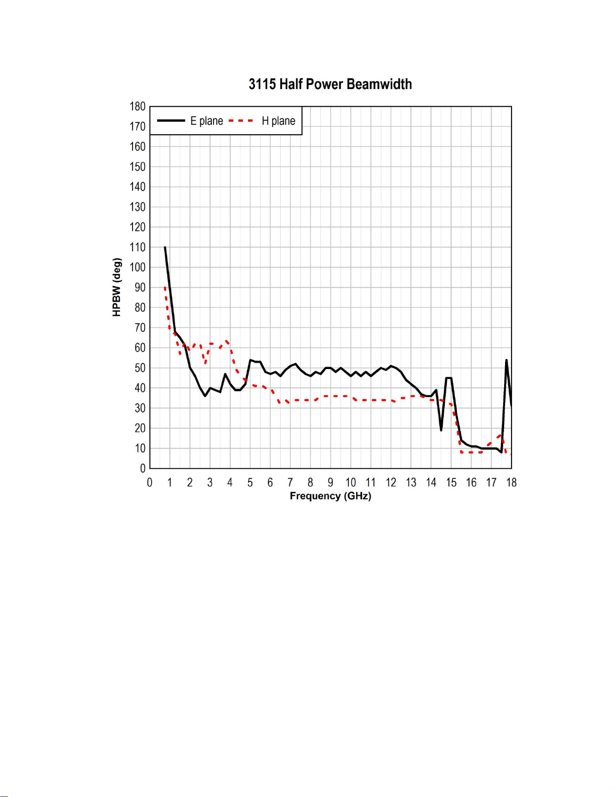
The Model 3115 Double-Ridged Waveguide
Horn is a linearly polarized broadband
antenna covering the frequency range of
750 MHz to 18 GHz.
The Model 3115 is ideally suited for
IEC 61000-4-3 and MIL-STD 461E immunity
tests as well as ANSI C634 and EN 55033
emissions testing. In addition, the 3115 is
useful for antenna pattern measurement as a
source antenna.
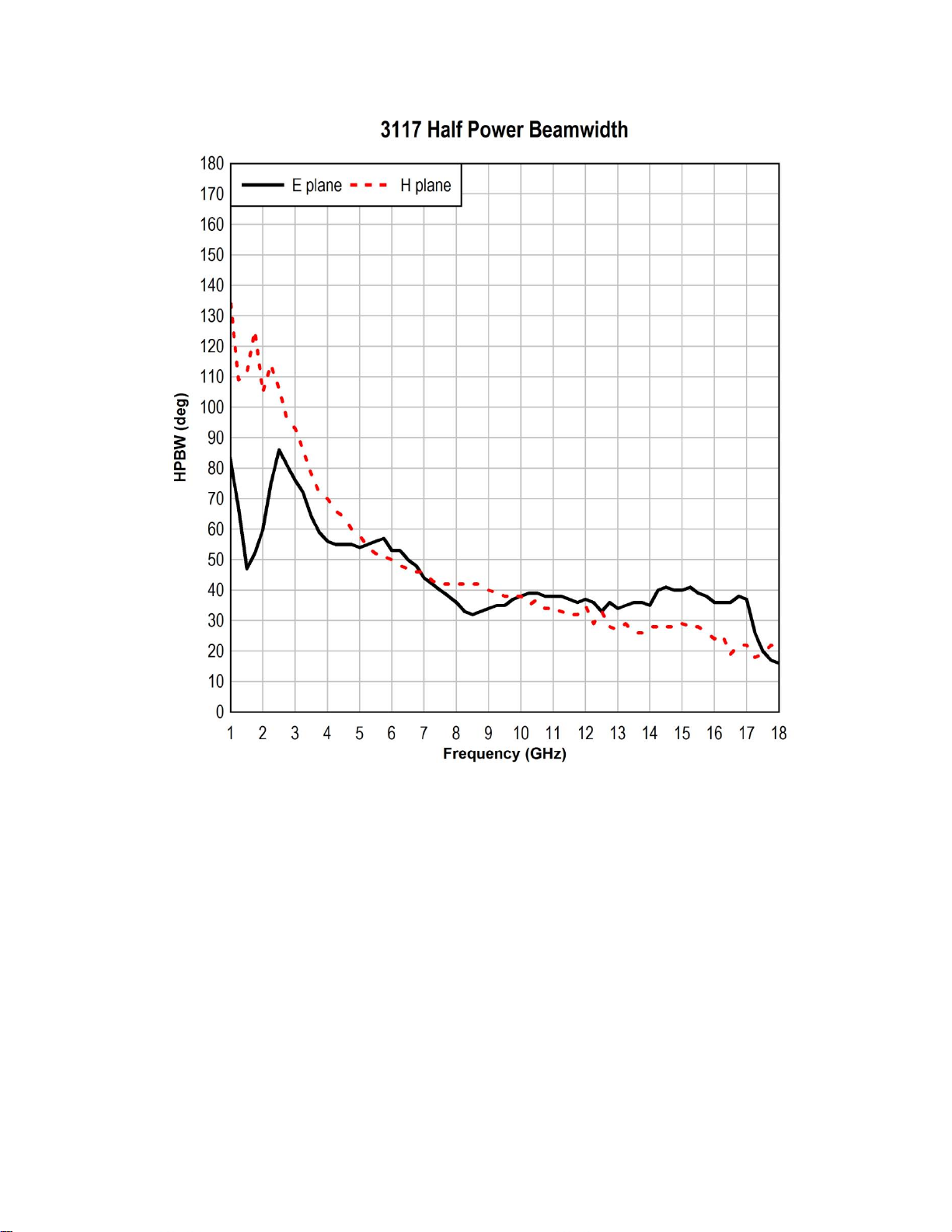
The Model 3117 Double-Ridged
Waveguide Horn is a linearly polarized
broadband antenna covering the 1 GHZ to
18 GHz frequency range.
A single well-defined main lobe radiation
pattern over the entire frequency range
provides excellent illumination of the
Equipment Under Test (EUT).
MODEL 3119
MODEL 3115
MODEL 3117
8 | Introduction
The Model 3117 is ideally suited for IEC 6100-4-3 and MIL-STD 661/462
immunity tests as well as ANSI C634 and EN 55033 emissions tests. The 3117
includes a stinger for flexible mounting options.
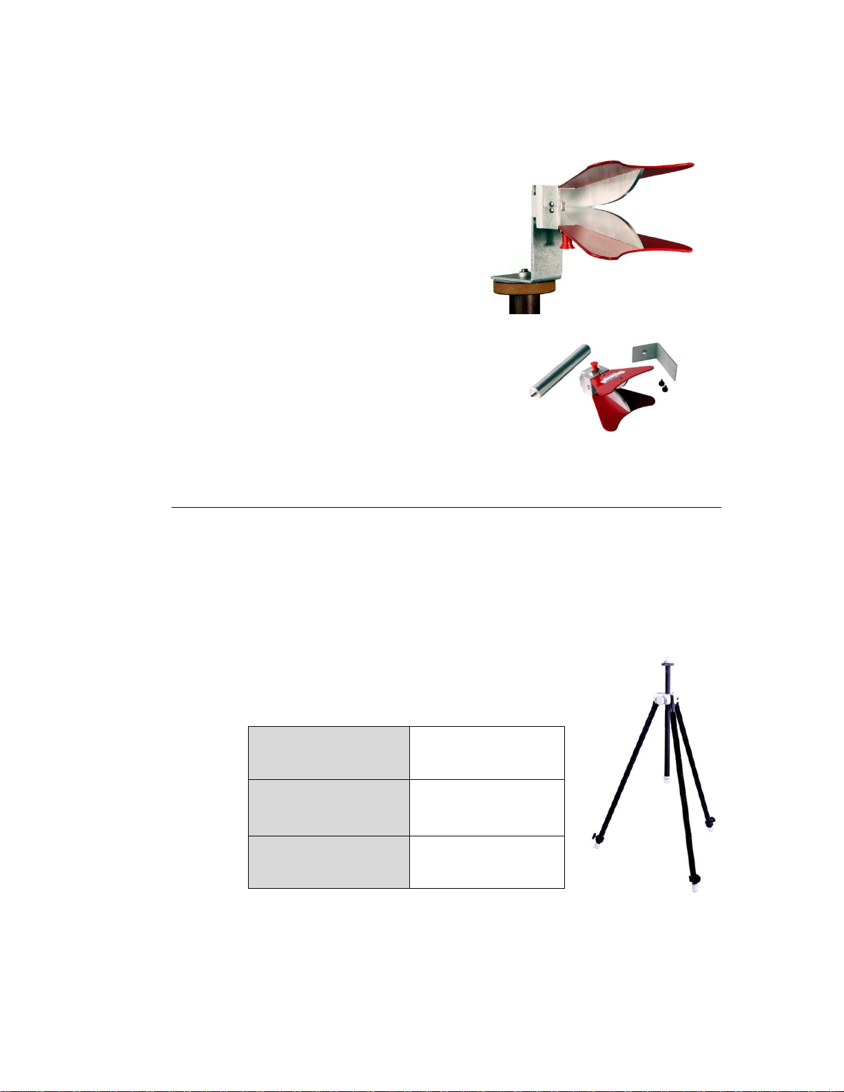
The Model 3116C Double-Ridged
Waveguide Horn is a linearly polarized
broadband antenna covering the
frequency range 10 GHz to 40 GHz. It is
designed and built specifically for
emissions and susceptibility testing.
The Model 3116C is precision-machined
from aluminum. A 50 Ω Type K
(2.92 mm) female connector is mounted
on the base block of the antenna for
increased performance at high
frequencies. For flexible mounting
options, the 3116C includes a bracket
that accepts a 1/4–20 thread screw and
a rear stinger-style mount.
4-TR Tripod—Constructed of linen phenolic and
delrin, designed with an adjustable center post for
precise height adjustments.
Maximum Height:
2.0 m (80.0 in)
Minimum Height:
94 cm (37.0 in)
Maximum Load:
11.8 kg (26.0 lb)
MODEL 3116C
Optional Items
TRIPOD OPTIONS
ETS-Lindgren offers the following non-metallic, non-reflective tripods for use at
both indoor and outdoor EMC test sites.
Introduction | 9
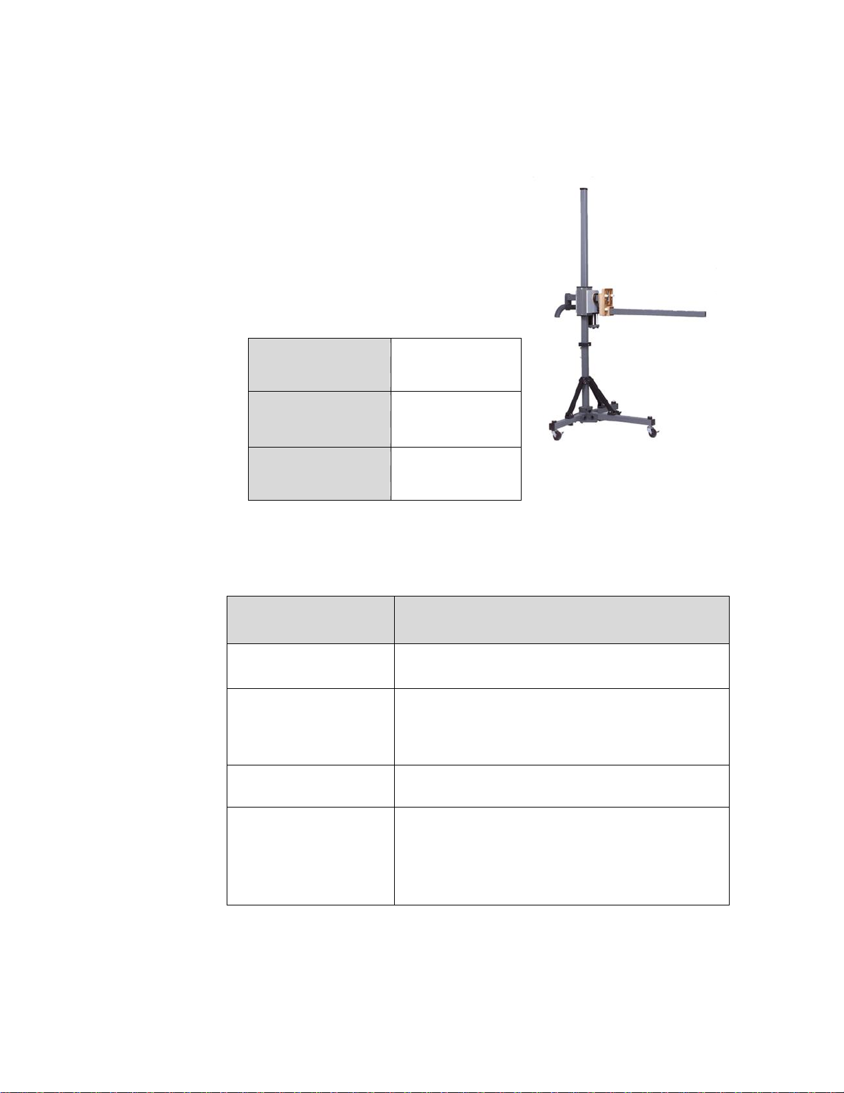
7-TR Tripod—Constructed of PVC and
fiberglass components, providing
increased stability for physically large
antennas. The unique design allows for
quick assembly, disassembly, and
convenient storage. Allows several
different configurations, including options
for manual or pneumatic polarization.
Quick height adjustment and locking
wheels provide ease of use during testing.
Maximum Height:
2.17 m (85.8 in)
Minimum Height:
0.8 m (31.8 in)
Maximum Load:
13.5 kg (30 lb)
Boom Type
Function
Straight (109042)
For general antenna mounting on a 7-TR.
Offset (108983)
For general antenna mounting on a 7-TR with
pneumatic or manual polarization. Can also be used
to mount stinger-type antennas.
Stinger Only (118947)
For stinger mount antennas only.
Centerline Rotation
(108507)
For Model 3106 Series antennas only; when
changing polarization, maintains centerline rotation.
For mounting information, see Mounting a
Model 3106 Series Antenna to a 7-TR on page 29.
7-TR BOOM OPTIONS
10 | Introduction
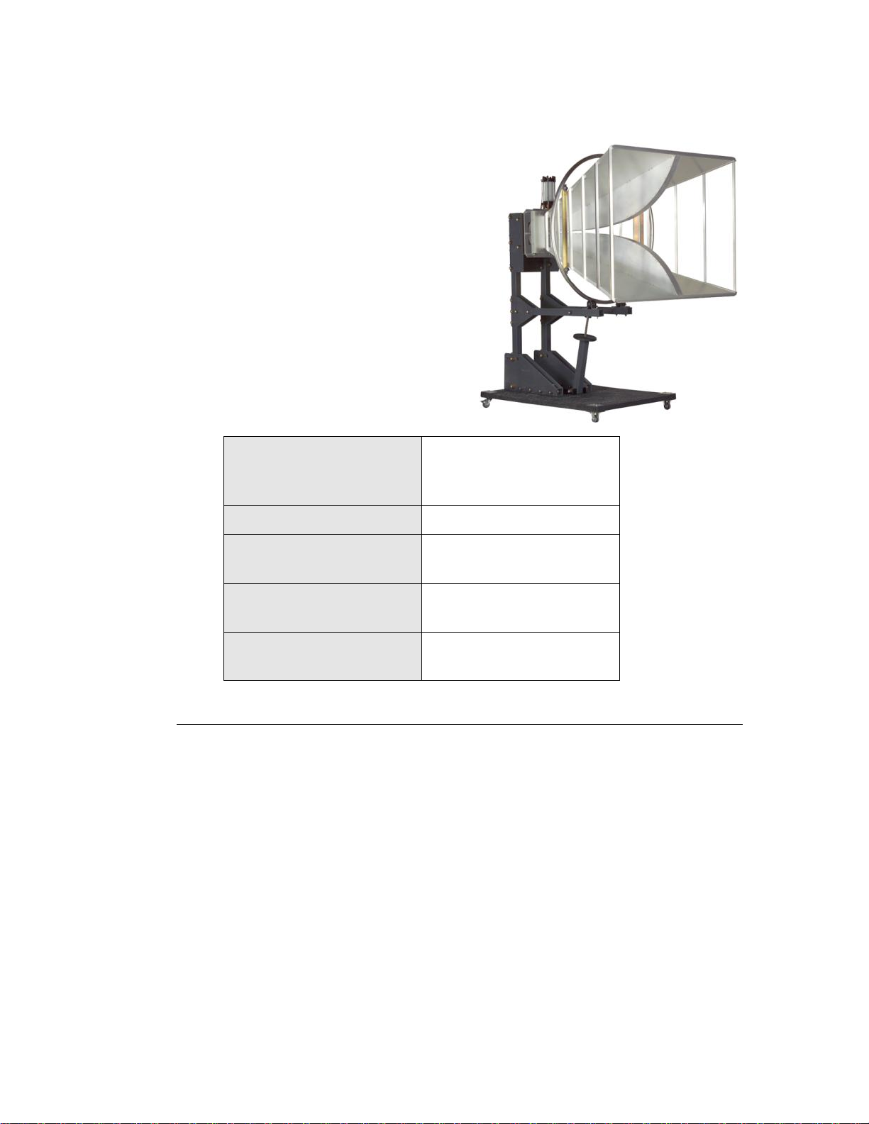
The Model 3112 features an option
for a fixed height pneumatic-assisted
polarization positioning system. The
position system is ideal when using
the Model 3112 for immunity testing.
Power Supply:
160 mA
120 VAC
Optional 220 VAC available
Pneumatic Interface:
50–80 PSI
Weight:
181.43–226.76 kg
400–500 lb
Maximum Height:
355.6 cm
140 in
Maximum Load:
194.13 cm
76.43 in
MODEL 3112 POSITIONING SYSTEM
ETS-Lindgren Product Information Bulletin
See the ETS-Lindgren Product Information Bulletin included with your shipment
for the following:
Warranty information
Safety, regulatory, and other product marking information
Steps to receive your shipment
Steps to return a component for service
ETS Lindgren calibration service
ETS Lindgren contact information
Introduction | 11

This page intentionally left blank.
12 | Introduction
Before performing any maintenance, follow the safety
information in the ETS-Lindgren Product Information
Bulletin included with your shipment.
Maintenance of a Double-Ridged Waveguide Horn Antenna
is limited to external components such as cables or
connectors.
If you have any questions concerning maintenance, contact
ETS Lindgren Customer Service.
ETS-Lindgren may substitute a similar part or new part number with the same
functionality for another part/part number. Contact ETS-Lindgren for questions
about part numbers and ordering parts.
Part Description
Part Number
Model 3112 Pneumatic Assisted Pedestal
109621
4-TR Tripod
4-TR
4-TR Mounting Bracket, 3115
101501
7-TR Tripod Options
7-TR Tripod, No Polarization
7-TR
7-TR Tripod, Pneumatic Polarization
7-TR/POL
7-TR Tripod, Manual Polarization
7-TR/POL-M
WARRANTY
2.0 Maintenance
Annual Calibration
See the Product Information Bulletin included with your shipment for information
on ETS-Lindgren calibration services.
Replacement and Optional Parts
Following are the part numbers for ordering replacement or optional parts for the
Double-Ridged Waveguide Horn Antennas.
Maintenance | 13

Part Description
Part Number
7-TR Boom Assembly Options
Boom Assembly, Antenna Mounting, Straight—Standard
for general antenna mounting on 7-TR
109042
Boom Assembly, Antenna Mounting, Offset—Standard
for general antenna mounting on 7-TR/POL and
7-TR/POL-M; can also be used to mount stinger-type
antennas.
108983
Boom,Stinger Only— For stinger-mount antennas only.
118947
Boom Assembly, Antenna Mounting, 3106—For
mounting Model 3106 antennas only.
108507
Service Procedures
For the steps to return a system or system component to ETS-Lindgren for
service, see the Product Information Bulletin included with your shipment.
14 | Maintenance

Frequency Range
100 MHz—1 GHz
VSWR Ratio (Average)
< 1.6:1
Maximum Continuous Power
800 W
Peak Power
1.5 kW (Type N, female connector)
2.5 kW CW (EIA 1 5/8-in flange connector)
Impedance (Nominal)
50 Ω
Connector
Type N, female
EIA 1 5/8-in flange
Front-to-Back Ratio
20 dB
Cross Polarization
20 dB minimum
Frequency Range
200 MHz—2.5 GHz
VSWR Ratio (Average)
<1.6:1
Maximum Continuous Power
800 W
Peak Power
1600 W
Impedance (Nominal)
50 Ω
Connector
Type N, female
Front-to-Back Ratio
20 dB
Cross Polarization
20 dB minimum
3.0 Specifications
Electrical Specifications
MODEL 3112
MODEL 3106B
Specifications | 15

Frequency Range
400 MHz—6 GHz
VSWR Ratio (Average)
3.5:1
Maximum Continuous Power
800 W
Peak Power
2500 W
Impedance (Nominal)
50 Ω
Connector
Type N, female (standard connector)
7/16 DIN (optional connector; must be
specified at time of purchase)
Front-to-Back Ratio
20 dB
Cross Polarization
20 dB minimum
Frequency Range
750 MHz—18 GHz
VSWR Ratio (Average)
5:1
Maximum Continuous Power
750 W
Peak Power
500 W
Impedance (Nominal)
50 Ω
Connector
Type N, female
Front-to-Back Ratio
20 dB
Cross Polarization
20 dB minimum
Frequency Range
1 GHz—18 GHz
VSWR Ratio (Average)
3.5:1 max
<2:1 above 1.5 GHz
Maximum Continuous Power
300 W
Peak Power
400 W
Impedance (Nominal)
50 Ω
Connector
Type N, female
Front-to-Back Ratio
>6.42 dB at 1 GHz
>12.08 dB at 2 GHz
>20 dB at 3 GHz—18 GHz
Cross Polarization
20 dB at 3 GHz—18 GHz
MODEL 3119
MODEL 3115
MODEL 3117
16 | Specifications

Frequency Range
10 GHz—40 GHz
VSWR Ratio (Average)
2.5:1 max
Maximum Continuous Power
20 W @ 40 GHz
40 W @ 10 GHz
Peak Power
200 W
Impedance (Nominal)
50 Ω
Connector
Type K, female
2.92 mm
Front-to-Back Ratio
20 dB
Cross Polarization
20 dB minimum
Width
203.2 cm (80 in)
Depth
182 cm (71.65 in)
Height
139.7 cm (56 in)
Approximate Weight
86.1 kg (189.81 lb)
Width
93.3 cm (36.7 in)
Depth
97.8 cm (38.5 in)
Height
72.9 cm (28.7 in)
Approximate Weight
11.8 kg (26.01 lb)
Width
48.84 cm (19.23 in)
Depth
40 cm (15.74 in)
Height
31.37 cm (12.35 in)
Approximate Weight
7.4 kg (16.3 lb)
MODEL 3116C
Physical Specifications
MODEL 3112
MODEL 3106B
MODEL 3119
Specifications | 17

Width
24.4 cm (9.6 in)
Depth
27.9 cm (11 in)
Height
15.9 cm (6.2 in)
Approximate Weight
1.8 kg (4 lb)
Width
17.5 cm (6.9 in)
Depth
17.5 cm + 15.5 cm mount
(6.9 in + 6.1 in mount)
Height
15.5 cm (6.1 in)
Approximate Weight
1.13 kg (2.5 lb)
With Stinger
With Bracket
Width
10.8 cm
4.25 in
Depth
25.73 cm
10.13 in
13.03 cm
5.13 in
Height
6.35 cm
2.5 in
8.9 cm
3.5 in
Approximate Weight
0.334 kg
0.74 lb
0.201 kg
0.44 lb
MODEL 3115
MODEL 3117
MODEL 3116C
18 | Specifications

Before connecting any components or operating the
Double-Ridged Waveguide Horn Antennas, follow the safety
information in the ETS-Lindgren Product Information Bulletin
included with your shipment.
The Double-Ridged Waveguide Horn Antennas are precision
instruments. Handle with care.
Make sure that no part of the antenna is in contact with the tripod or tower.
Due to the size of the Model 3112, 3119, and 3106B
Double-Ridged Waveguide Horn Antennas, do not mount them
onto a 4-TR.
Failure to provide continuous support of the antenna when
attaching or removing the mounting bracket or thumbscrews may
result in damage.
The Model 3117 Model and 3116C include a stinger mount for centerline
rotation measurements; see page 21 for more information.
4.0 Mounting Instructions
4-TR Mounting Instructions
INCLUDED MOUNTING HARDWARE
All Double-Ridged Waveguide Horn Antennas (except the 3112, 3119,
and 3106B) mount directly to a 4-TR Tripod using the included mounting
hardware; no additional hardware is required.
All Double-Ridged Waveguide Horn Antennas ship with the following mounting
hardware:
Mounting bracket drilled to accept ETS-Lindgren or other tripod mount with
1/4–20 threads.
Thumbscrews (2) for attaching the antenna to the mounting bracket.
Mounting Instructions | 19
The Model 3117 Model and 3116C include a stinger mount for centerline
rotation measurements; see page 21 for more information.
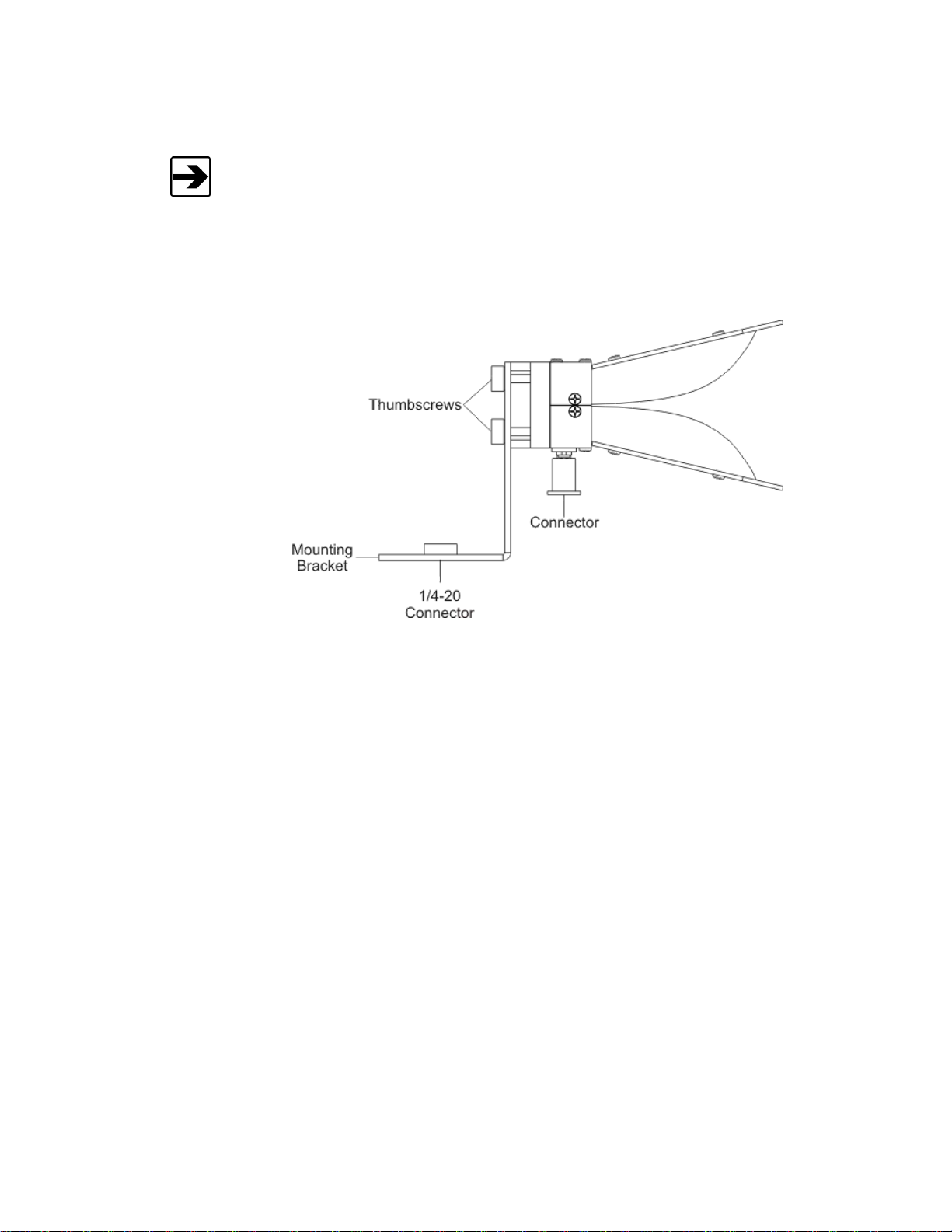
ATTACH MOUNTING BRACKET TO ANTENNA
The following illustration represents a typical assembly of the mounting bracket to
an antenna. The Model 3116C is shown; however, the steps are similar for each
of the Double-Ridged Waveguide Horn Antennas.
1. Hold the antenna with the connector pointing to the floor and align the
holes on the back of the antenna with the ones on the bracket provided.
2. Select set of holes for horizontal or vertical polarization as desired.
3. Insert both thumbscrews and tighten.
20 | Mounting Instructions
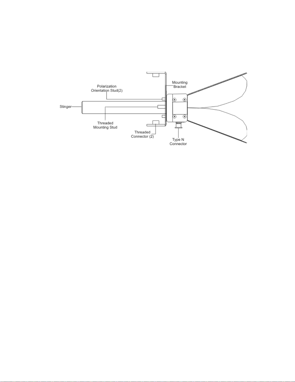
ATTACH STINGER MOUNT (MODELS 3117 AND 3116C ONLY)
The Model 3117 Model and 3116C include a stinger mount for centerline rotation
measurements.
1. Hold the antenna with the connector pointing to the floor and align the
holes on the back of the antenna with the ones on the bracket provided.
2. Select set of holes for horizontal or vertical polarization as desired.
3. Insert both thumbscrews and tighten.
4. Align the stinger with the threaded mounting stud then tighten.
Mounting Instructions | 21

1. Attach the mounting bracket
to the 4-TR by aligning the
1/4–20 connector on the
bracket with the 1/4–20 bolt
on the tripod. Support the
antenna securely while
turning the mounting bracket
to tighten the connection.
2. To change polarization,
support the antenna securely
and remove the
thumbscrews. Turn the
antenna to align the holes on
the mounting bracket with
the desired set of holes on
the back of the antenna.
Re-insert the thumbscrews
and tighten.
Model 3117 shown
mounted onto 4-TR
MOUNT ANTENNA AND BRACKET TO 4-TR
22 | Mounting Instructions
Due to the size of the Model 3112, do not mount it onto a 7-TR.
For a list of 7-TR boom options, see page 10. For 7-TR mounting instructions,
see the 7-TR manual.
For instructions to mount a Model 3106B to a 7-TR, see page 29.
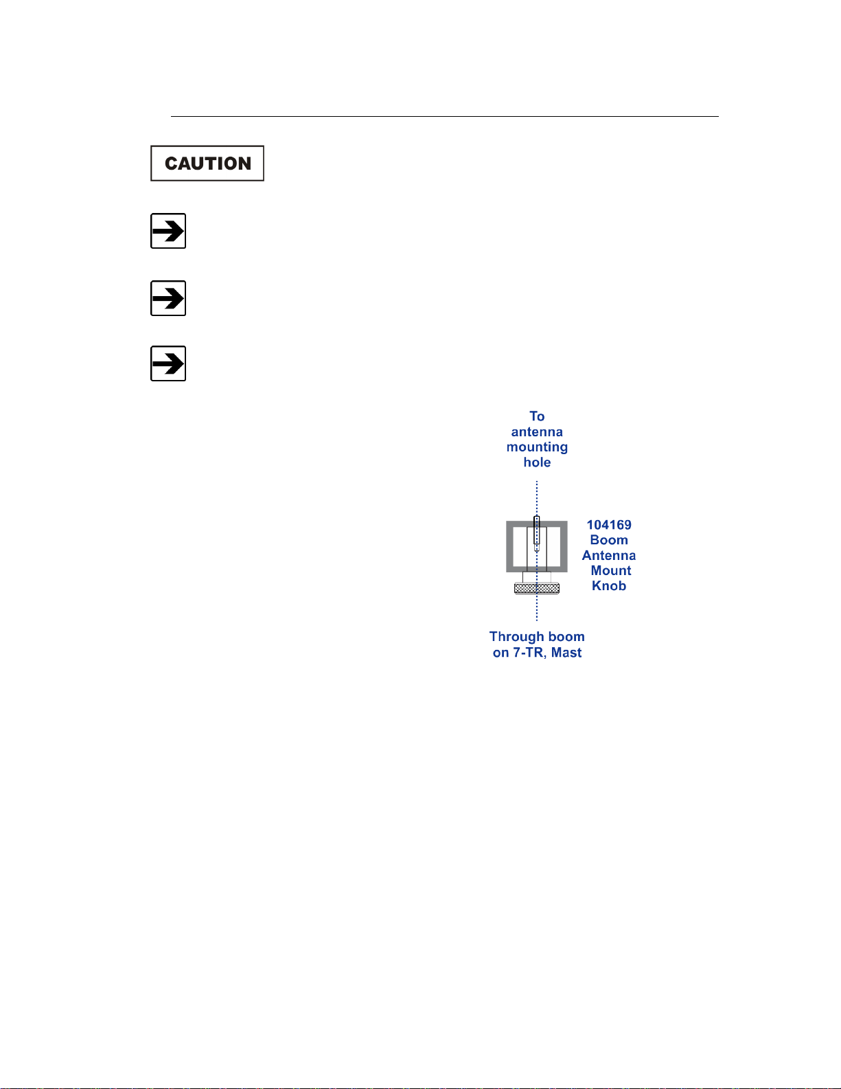
The stinger on the Model 3117 and Model 3116C enables you to mount the
antenna directly to an ETS-Lindgren 7-TR without additional hardware.
This illustration provides an option
for mounting a Double-Ridged
Waveguide Horn Antenna (except
Model 3106B and Model 3112) onto
an ETS-Lindgren 7-TR Tripod or
mast. Contact the ETS-Lindgren
Sales Department for information on
ordering optional mounting
hardware.
7-TR and Mast Mounting Options
Mounting Instructions | 23
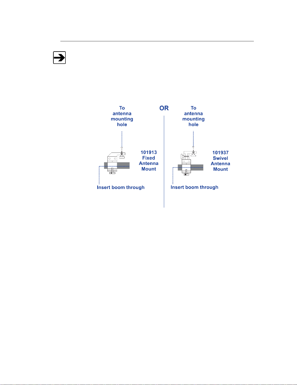
2x2 boom refers to a typical 2-inch by 2-inch boom.
2x2 Boom Mounting Options
Following are options for mounting a Double-Ridged Waveguide Horn Antenna
onto a 2x2 boom. Contact the ETS-Lindgren Sales Department for information on
ordering optional mounting hardware.
24 | Mounting Instructions

Before connecting any components or operating the
Double-Ridged Waveguide Horn Antennas, follow the safety
information in the ETS-Lindgren Product Information Bulletin
included with your shipment.
Failure to provide continuous support of the antenna when
attaching or removing the antenna from the positioning system
may result in damage and/or personal injury.
The customer is responsible for providing an adequate and safe support
system for the Model 3112 Double-Ridged Waveguide Horn when moving
and attaching to the optional positioning system.
The Model 3112 Double Ridged
Waveguide Horn Antenna includes a
series of outer holes in the rear plate
that is compatible with the optional
positioning system. Additionally, the
mounting holes can be used to meet
customer-specific mounting
requirements.
5.0 Mounting a Model 3112 to the Optional Positioning System
Rear Plate Mounting Pattern
Mounting a Model 3112 to the Optional Positioning System | 25

26 | Mounting a Model 3112 to the Optional Positioning System
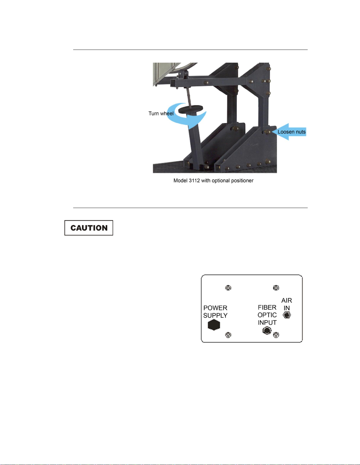
Once the
Model 3112 is
securely
mounted on the
positioner, loosen
the nuts and turn
the wheel at the
base of the horn
support for better
field uniformity.
This bore sights
the horn 10
degrees.
Do not connect power to the positioner until the antenna is
securely mounted and all connections have been made.
Plug one end of the fiber optic
cable into the FIBER OPTIC
INPUT connector.
Plug the opposite end of the
fiber optic cable into the ETSLindgren Model 2090 MultiDevice Controller or
compatible controller.
Connecting the Optional Positioning System
Input Locations
The input panel is located on the base of the Model 3112 positioner.
Plug the cord included first into the POWER SUPPLY outlet. Make
connection with the power source only once all other connections have
been made and the antenna is securely attached to the positioner.
Mounting a Model 3112 to the Optional Positioning System | 27
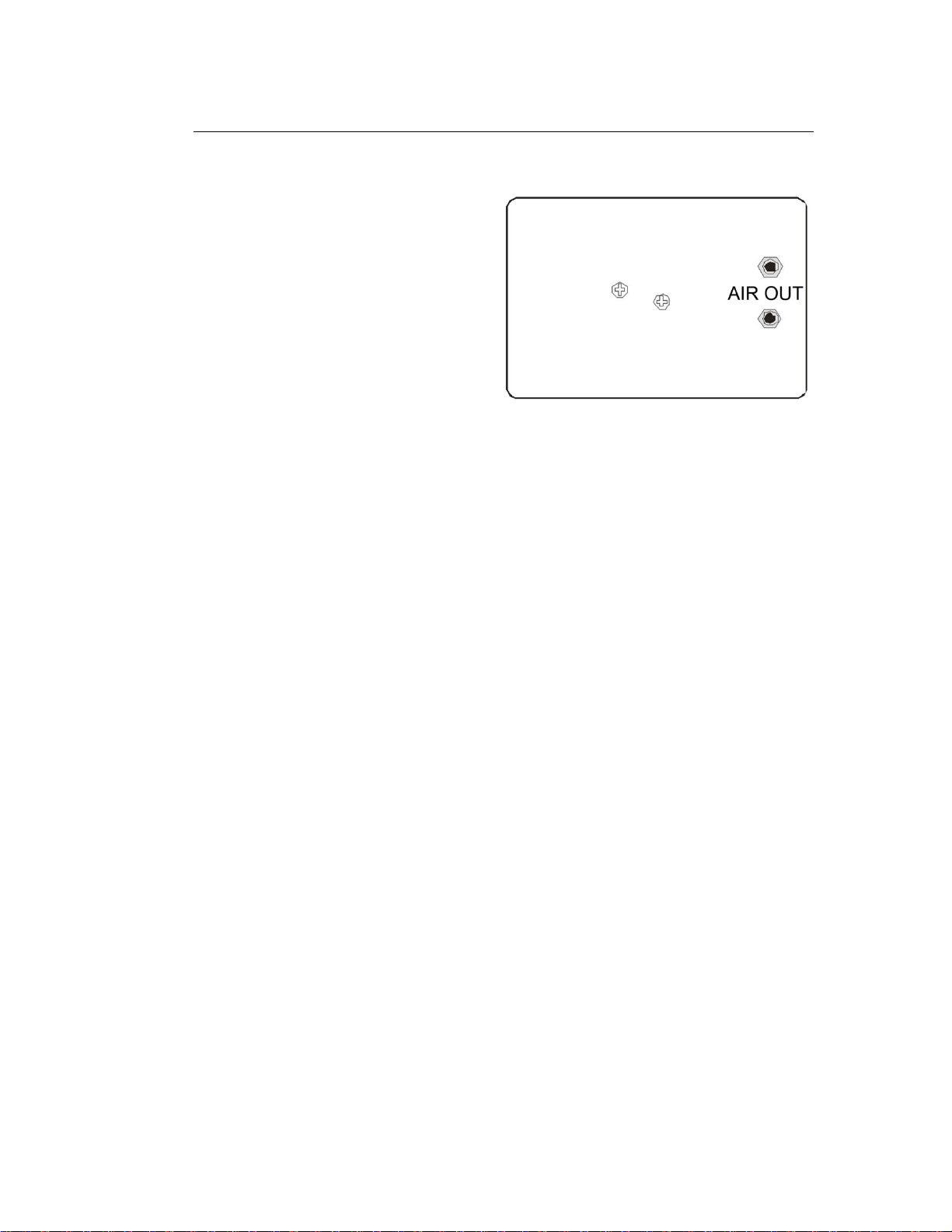
Plug the ends of the twin air
hoses into the two AIR OUT
connectors located on the
interface box at the base of
the custom positioning
system.
Plug the opposite ends of
the twin hoses into the two
90 degree fittings on the air
cylinder of the custom
positioning system.
Air Polarization Option
Plug one end of the single air hose into the AIR IN connector located on the
opposite side of the interface box at the base of the custom positioning
system (shown in previous diagram).
Plug the opposite end of the single air hose into the air supply.
Once the antenna is completely secure and the connections are made,
connect the power supply to the POWER SUPPLY port on the opposite side
of the interface box at the base of the custom positioning system (show in
previous diagram).
28 | Mounting a Model 3112 to the Optional Positioning System

Before connecting any components or operating the
Double-Ridged Waveguide Horn Antennas, follow the safety
information in the ETS-Lindgren Product Information Bulletin
included with your shipment.
You will need assistance from two team members to mount a
Model 3106 Series antenna to the 7-TR.
You must install the 108507 boom onto the 7-TR before performing these
steps. For clarity, the following illustrations do not show the 7-TR.
ETS-Lindgren may substitute a similar part with the same functionality for
another part (for example, a wingnut for a hex nut).
Step 1
Remove the two 104136 boom
knobs from the underside of the
108507 boom. You will re-use
the knobs in Step 7.
6.0 Mounting a Model 3106 Series Antenna to a 7-TR
The following steps to mount a Model 3106B Double-Ridged Waveguide Horn
Antenna onto a 108507 boom apply to all Model 3106 Series antennas.
Mounting a Model 3106 Series Antenna to a 7-TR | 29

Step 2
Lift the mount adapter up
and away from the boom.
Step 3
Remove the wingnut to free the
1/4–20 screw from the mount
adapter. You will re-use the
screw in Step 6.
Step 4
Remove the nuts to free the
two screws from the vertical
plate on the mount adapter.
You will re-use the screws in
Step 6.
30 | Mounting a Model 3106 Series Antenna to a 7-TR
Retain these two screws for future use; if you remove the Model 3106B from
the 7-TR, you will need to replace these screws to provide support for the
inner ridge of the antenna.
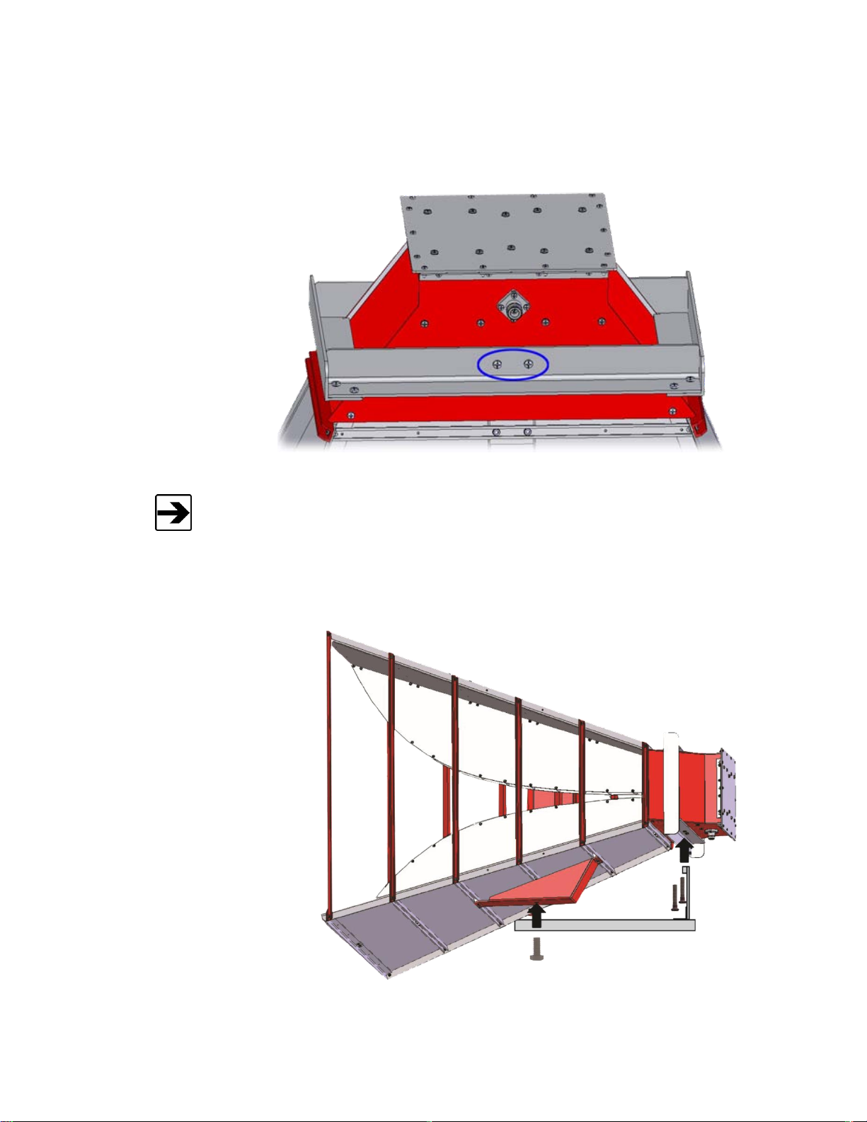
Step 5
On the side of the
Model 3106B with the
antenna connector,
remove the two screws
from the mount plate.
Step 6
Attach mount adapter to the
Model 3106B:
Using the two screws
removed in Step 4, insert
the screws through the lip
on the vertical part of the
mount adapter and into
the two holes on the
antenna. Tighten to
secure.
Using the screw removed
in Step 3, insert the screw
through the horizontal
part of the mount adapter
and into the mount block
on the antenna. Tighten
to secure.
Mounting a Model 3106 Series Antenna to a 7-TR | 31

Step 7
Attach the mounted assembly to the boom: Use the two 104136 knobs removed in
Step 1 to attach the antenna and mount adapter assembly to the boom. Tighten to
secure.
32 | Mounting a Model 3106 Series Antenna to a 7-TR
Before placing into operation, follow the safety information in the
ETS-Lindgren Product Information Bulletin included with your
shipment.
7.0 Typical Data
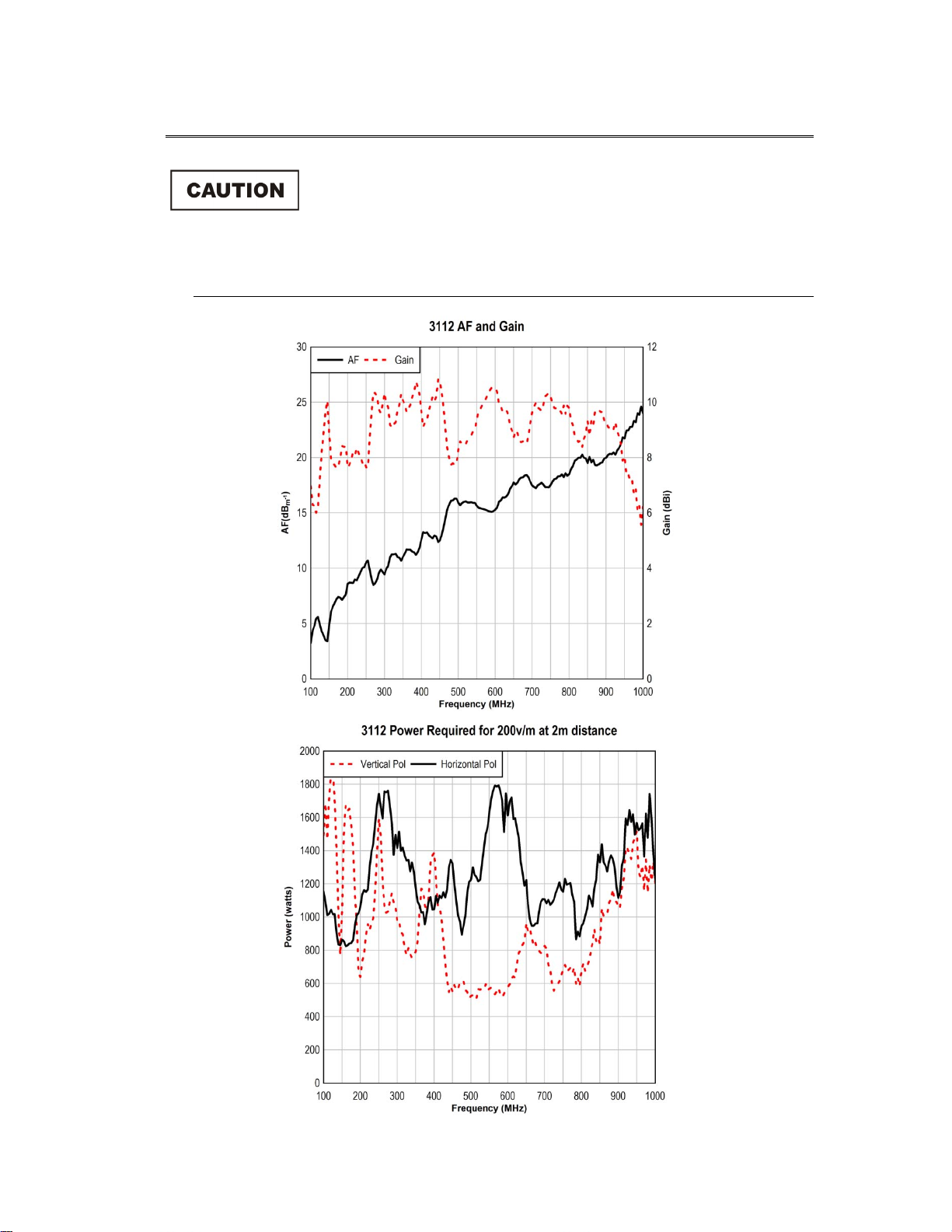
Model 3112
Typical Data | 33

34 | Typical Data
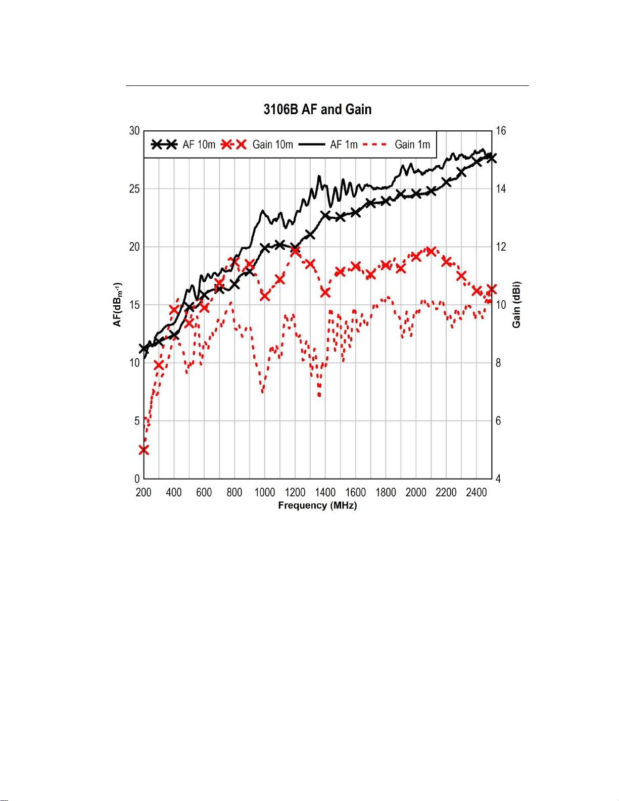
Model 3106B
Typical Data | 35

36 | Typical Data

Model 3119
Typical Data | 37

38 | Typical Data

Typical Data | 39

Model 3115
40 | Typical Data
Typical Data | 41

42 | Typical Data
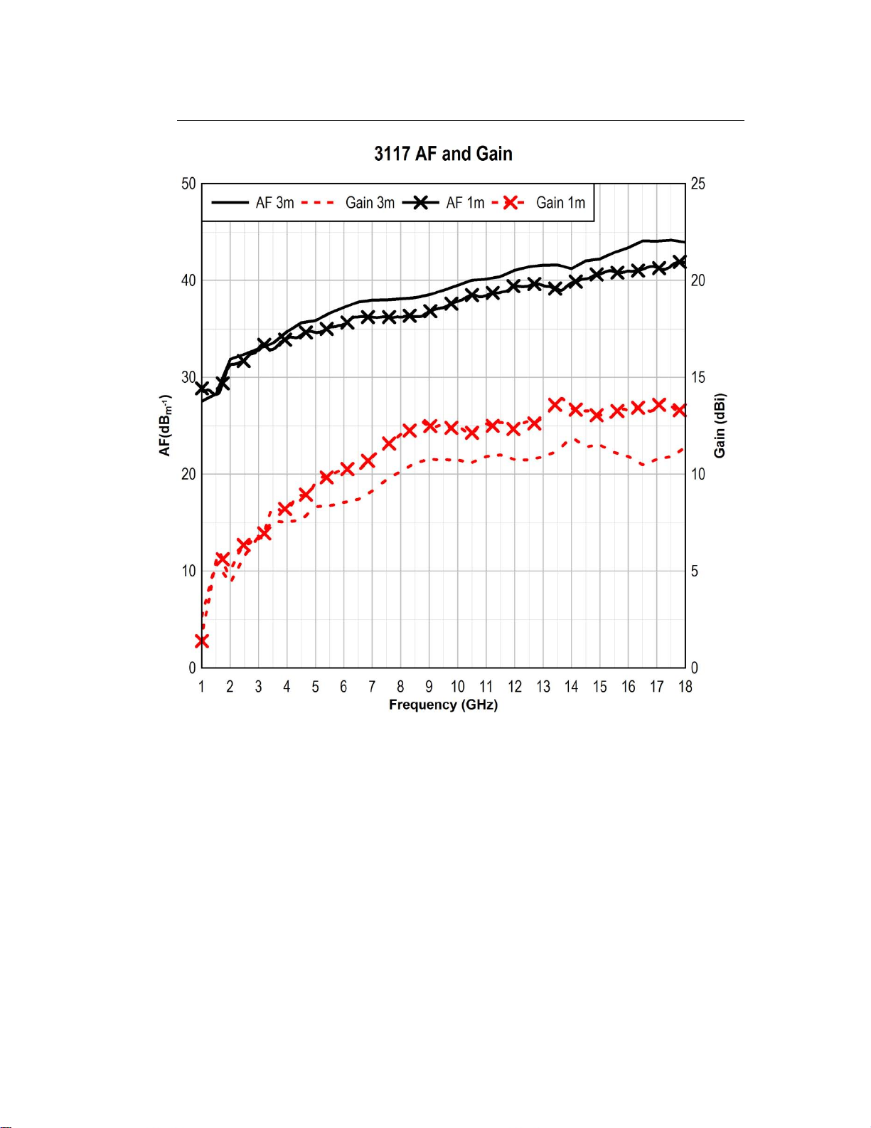
Model 3117
Typical Data | 43
44 | Typical Data

Typical Data | 45

Model 3116C
46 | Typical Data

Typical Data | 47

48 | Typical Data

See the Product Information Bulletin included with your shipment for the complete
ETS-Lindgren warranty for your Double-ridged Waveguide Horn Antenna.
Product Warranted
Duration of Warranty Period
Model 3112
2 Years
Model 3106B
2 Years
Model 3119
2 Years
Model 3115
2 Years
Model 3117
2 Years
Model 3116C
2 Years
Appendix A: Warranty
DURATION OF WARRANTIES FOR DOUBLE-RIDGED WAVEGUIDE HORN ANTENNAS
All product warranties, except the warranty of title, and all remedies for warranty
failures are limited to two years.
Warranty | 49

This page intentionally left blank.
50 | Warranty

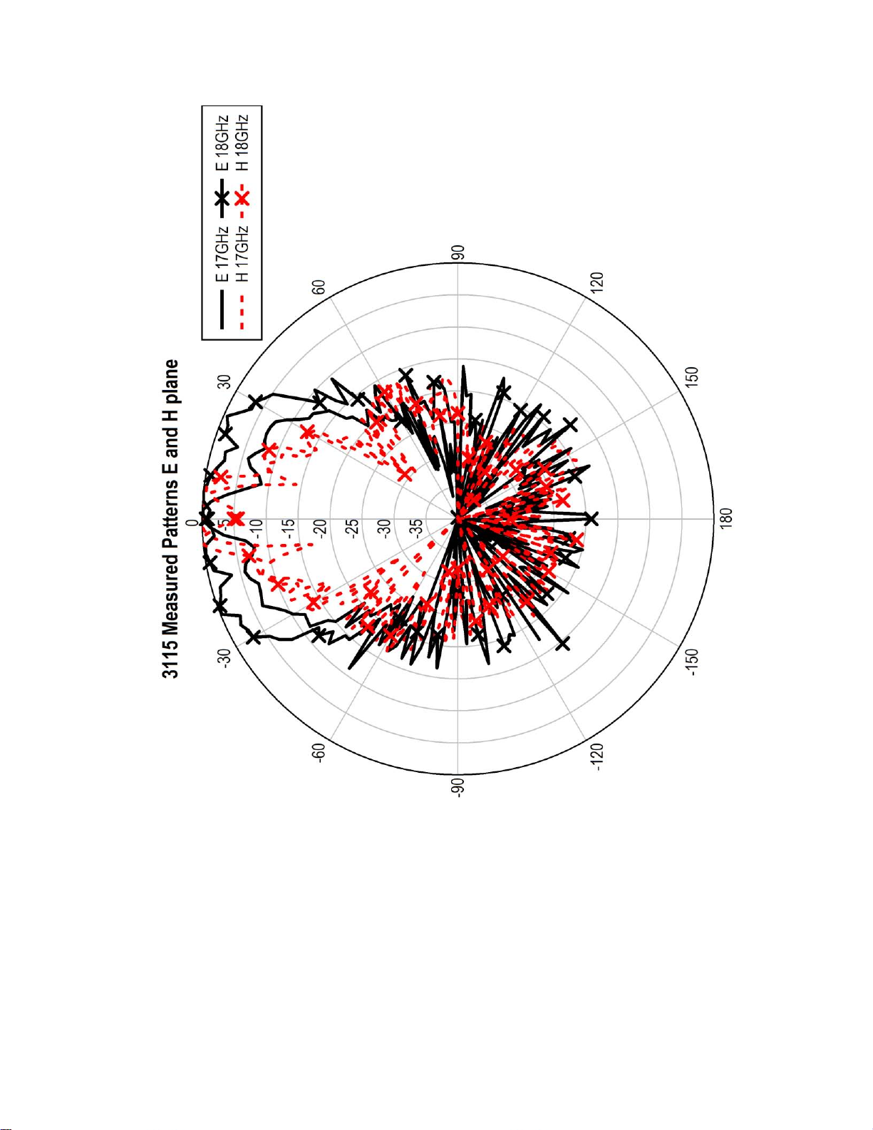
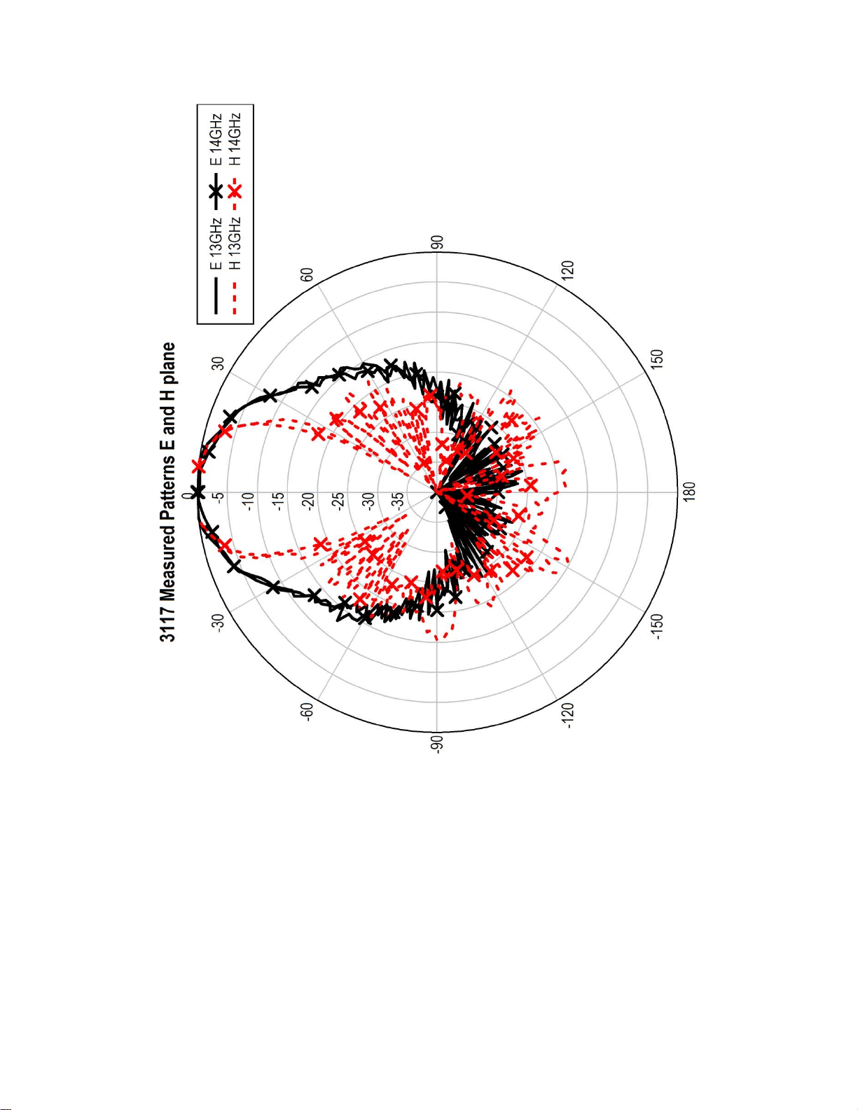
Appendix B: Typical Measured Radiated Patterns
Model 3106B
Typical Measured Radiated Patterns | 51

52 | Typical Measured Radiated Patterns

Typical Measured Radiated Patterns | 53

54 | Typical Measured Radiated Patterns

Typical Measured Radiated Patterns | 55

Model 3119
56 | Typical Measured Radiated Patterns

Typical Measured Radiated Patterns | 57
58 | Typical Measured Radiated Patterns

Typical Measured Radiated Patterns | 59

60 | Typical Measured Radiated Patterns

Typical Measured Radiated Patterns | 61

Model 3115
62 | Typical Measured Radiated Patterns

Typical Measured Radiated Patterns | 63

64 | Typical Measured Radiated Patterns

Typical Measured Radiated Patterns | 65

66 | Typical Measured Radiated Patterns
Typical Measured Radiated Patterns | 67

Model 3117
68 | Typical Measured Radiated Patterns

Typical Measured Radiated Patterns | 69

70 | Typical Measured Radiated Patterns

Typical Measured Radiated Patterns | 71

72 | Typical Measured Radiated Patterns

Typical Measured Radiated Patterns | 73

74 | Typical Measured Radiated Patterns

Typical Measured Radiated Patterns | 75
76 | Typical Measured Radiated Patterns

Typical Measured Radiated Patterns | 77

78 | Typical Measured Radiated Patterns

Typical Measured Radiated Patterns | 79
 Loading...