

Escorts FarmTrac 45 DT Operator's Manual
OPERATOR ’ S
M A N U A L
OPERATOR ’ S
M A N U A L
45 DT

2
CONTENTS
Page
Limited Warranty ii
Federal Emission Warranty iii-iv
Introduction v
Safety Precautions vi-viii
Universal Symbols ix
Road Speed Decal ix
Safety Decals x
CONTROLS, INSTRUMENTS AND OPERATION
Operator’s Seat, Seat Belt, Safety Frame or Roll Bar 2
Instruments and Controls 2
Starting the Engine 4
Stopping the Engine 5
Parking Brake 5
Foot Controls 6
Transmission 7
Power-Take-Off 7
Hydraulic System 9
Three Point Linkage 14
Track Adjustment 17
Tractor Weighing 20
Tire Inflation 22
LUBRICATION AND MAINTENANCE
Lubrication and Maintenance Chart B/2
Routine Servicing B/4
General Maintenance B/21
SPECIFICATIONS
INDEX
SECTION A
SECTION B
SECTION C
SECTION D

LIMITED WARRANTY
FARMTRAC AGRICULTURAL TRACTORS
ESCORTS LIMITED warrants to its overseas Authorized Dealers that each new Farmtrac Agricultural tractor sold
by it to the Authorized Dealer will be free, under normal usage and service, from defects in materials and workmanship
for a period of one (1) year or one thousand (1000) hours of operation, whichever is earlier, from the date of sale to
the first original retail purchaser. Escorts Limited’s obligation under this warranty is limited to repairing or replacing
at its own, sole and absolute option in an Authorized Dealer’s place of business any part or parts that, within the
warranty period, are returned to its Authorized Dealers with transportation charges prepaid. Escorts Limited’s inspection
must show that the returned part or parts were defective at the time of manufacture. Parts replaced pursuant to this
warranty shall be warranted only for the remainder of the warranty period applicable to the tractor.
This warranty is expressly limited to the repair or replacement of the defective parts as set forth herein and is the
only warranty given by Escorts Limited and is in lieu of any and every warranty of every kind either expressed or
implied, and this warranty cannot be changed, modified or added to except in writing by a duty elected officer of
Escorts Limited and no dealer, distributor, agent, salesman or representative has any right or authority to change,
modify or enlarge this warranty or to make any promise, stipulation and/or agreement inconsistent or in conflict
therewith.
This warranty does not apply if the tractor or any part thereof has been subjected to misuse or negligence on the
part of the owner or operator, or accident. This warranty does not extend to expendable and consumable items
including such items as brake discs, clutch discs, air filters, engine and hydraulic oil, oil filters, fan belts and light
bulbs. This warranty does not cover normal maintenance services such as engine tune-up, cleaning or minor
adjustments. This warranty also does not apply to tractors which have been fitted with any part or parts which have
not been made or supplied by Escorts Limited.
IMPORTANT
No other warranty whether or merchantability, fitness or otherwise, expressed or implied, in fact
or by law, is given by Escorts Limited with respect to any new tractor or part and no other or
further obligation or liability shall be incurred by Escorts Limited by reason of the manufacture or
sale of any new tractor or part whether for breach of any warranty, negligence of manufacture or
otherwise.
The obligations of Escorts Limited set forth in the first paragraph hereinabove shall be the exclusive remedy for any
breach of warranty hereunder. In no event shall Escorts Limited be liable for any general, consequential or incidental
damages including, without limitations, any damages for loss of use or loss of profits.
Farmtrac tractors sold through other than Authorized Dealers are not subject to standard warranty and service
policies of Escorts Limited.
Escorts Limited has a Company policy of continuous improvement and development. Escorts Limited reserves the
right to make changes or improvements at any time without incurring any obligations whatsoever to make such
changes on products sold previously.
This warranty becomes effective upon receipt of a properly completed Pre-Delivery Inspection Report by its Overseas
Authorized Dealers or Distributors.
Escorts Limited makes no warranty with respect to proprietary articles such as tires, tubes batteries etc. which
may be fitted in an overseas territory since such products are warranted separately by the respective manufacturers.
This warranty shall not apply to any tractor or part there of that has been repaired or altered outside of Escorts
Limited’s factor or an Authorized Dealer’s Shop.
SAFETY INSTRUCTIONS
ii

SAFETY INSTRUCTIONS
FEDERAL EMISSIONS WARRANTY
(Applicable only to Tractors sold in United States of America)
Escorts Limited warrants that each new 2002 and later non-road diesel engine fitted on your Farmtrac Agricultural
tractor was designed, built and equippped to confirm to applicable U.S. Environment Protection Agency regulations
for a period of five years of three thousand (3,000) hours of operation, whichever is earlier, from the date of sale to
the first original retail purchaser.
The new model year, class of diesel engine and emission application determination for your engine are identified on
the emission control information label affixed to the top of your engine’s rocker arm cover (see on the next page).
This warranty is expressly limited to repair or replacement of any emission control system parts, which are proven
defective during normal use during the warranty period. The warranty repairs and service will be performed by any
Authorized Dealer of Escorts Limited at the Dealer’s place of business. Parts replaced pursuant to this warranty
shall be warranted only for the remainder of the warranty period applicable to the tractor. This emission control
system warranty applies to the following emission control parts:
Fuel Injection Pump Intake Manifold
Fuel Injectors Exhaust Manifold.
High Pressure Pipes
As a tractor owne, your are responjsible for performing all the required engine maintenance listed in your Owner’s
Manual. Escorts Limited will not deny an emission warranty claim solely for lack of maintenance records with you.
However, a claim may be denied if your failure to perform maintenance resulted in the failure of a warranted part.
Receipts covering regular maintenance should be retained in the event of any clarifications required and these
receipts should be passed to each subsequent owner of the tractor.
To maintain the quality and performance originally designed into your emission certified engine, it is recommended
that only replacement parts supplied by Escorts Limited be used for maintenance or repairs. The use of parts not
supplied by Escort Limited does not invalidate the warranty on other components unless the use of such parts
causes damage to warranted parts. If you beliueve you have not received the service entitled to under this warranty,
you should contact us for assistance at the following address:
Export Department
Agri. Machinery Marketing Division,
Escort Limited,
18/4 Mathura Road,
Faridabad - 121 007, INDIA.
Phone - (91) (0129) 5283071
Fax - (91) (0129) 5284839
Please note that the Emission Warranty does not cover:
1. Systems and Parts that were not first installed on your tractor or engine as original equipment by Escorts
Limited.
2. Part malfunctions caused by abuse, misuse, improper adjustment, modification, alteration, tampering,
disconnection, improper, or inadequate maintenance, or use of non-recommended fuels and lubricating oils.
3. Accident caused damage, acts of nature, or other events beyond Escorts Limited’s control.
4. Replacement of expendable items made in connetion with scheduled maintenance.
5. Parts requiring replacement, inspection or adjustment at regular maintenance intervals for reasons other than
being defective.
iii

6. Parts which are not Escorts Limited’s Service Parts.
7. Loss of time, inconvenience, loss of use of equipment/engine or commercial loss.
8. Equipment with altered or disconnected hourmeter where the hours cannot be determined.
9. Equipment not sold by Escorts Limited in United States or normally operated outside the United States.
10. Non defective parts replaced by other that Escorts Limited’s Dealers.
This warranty becomes effective upon receipt of a properly completed Pre-Delivery Inspection Report by the
Authorized Dealers of Distributors of Escorts Limited.
SAFETY INSTRUCTIONS
EMISSION CONTROL INFORMATION LABELS
NOTE : The Model year shown on the Emission Control Information Lable changes as applicable.
IMPORTANT ENGINE INFORMATION
EPA ENGINE FAMILY : XAELL 2.86 FTD TAPPET CLEARANCE-IN (COLD) : 0.014-0.018 inch
ENGINE MODEL : F3.287 TAPPET CLEARANCE-EX (COLD) : 0.017-0.021 inch
DISPLACEMENT : 2.86 Lts. INJECTION TIMING (STATIC) : 120 BTDC
ADVERTISED POWER : 29KW NET (ISO 2288) HIGH IDLING SPEED : 2300-2400 RPM
RATED SPEED : 2000 RPM LOW IDLING SPEED : 600-700 RPM
• ·THIS ENGINE CONFORMS TO 1999 U.S. EPA REGULATION FOR LARGE NON-ROAD COMPRESSION
IGNITION ENGINES.
• THIS ENGINE IS CERTIFIED TO OPERATE ON COMMERCIALLY AVAILABLE DIESEL FUEL
IMPORTANT ENGINE INFORMATION
EPA ENGINE FAMILY : XAELL 3.14 FTD TAPPET CLEARANCE-IN (COLD) : 0.014-0.018 inch
ENGINE MODEL : F3.315 TAPPET CLEARANCE-EX (COLD) : 0.017-0.021 inch
DISPLACEMENT : 2.86 Lts. INJECTION TIMING (STATIC) : 120 BTDC
ADVERTISED POWER: 34.9KW NET (ISO 2288) HIGH IDLING SPEED : 2300-2400 RPM
RATED SPEED : 2000 RPM LOW IDLING SPEED : 600-700 RPM
• THIS ENGINE CONFORMS TO 1999 U.S. EPA REGULATION FOR LARGE NON-ROAD COMPRESSION-
IGNITION ENGINES.
• THIS ENGINE IS CERTIFIED TO OPERATE ON COMMERCIALLY AVAILABLE DIESEL FUEL
(a) FARMTRAC 45
(a) FARMTRAC 60
iv

INTRODUCTION
Thankyou for purchasing your new Farmtrac tractor.
This Manual has been prepared to assist you in the correct procedure for running-in, driving and operating your new
tractor and to assist you in the correct method of maintenance to keep it in peak condition.
Your tractor has been designed and built to give maximum performance, economy and ease of operation under a
wide variety of operating conditions. Prior to delivery, the tractor was carefully inspected, both at the factory and
by your Authorized Dealer to ensure that it reaches you in optimum condition. To maintain this condition and ensure
trouble-free operation, it is important that the routine services, as specified in this manual, are carried out at the
recommended intervals.
Pages vi to viii inclusive, list the precautions to be observed to ensure your safety and the safety of others. Read
the safety precautions and follow the advice offered before operating the tractor.
A vehicle identification plate is located under the tractor bonnet. The vehicle reference serial number are also
recorded on the pre-delivery inspection sheet that was provided to you by your Authorized Dealer and should be quoted
to the Dealer should the tractor require service.
Read this Manual carefully and keep it at a convenient place for future reference. This manual must be considered
as an integral part of your tractor. If at any time you require service or advice concerning your tractor, do not
hesitate to contact your Authorized Dealer. He has trained personnel, genuine parts and the necessary equipment to
carry out all your service requirements.
Following these introductory pages, this manual is split into four sections. Section A describes the controls and
instruments and advises the correct method of operating your new tractor. Section B details lubrication and maintenance procedures and includes a comprehensive service chart. Section C outlines the specifications of your tractor.
A comprehensive index is provided at the back of the Manual in Section D.
Escorts Limited has a Company policy of continuous improvement and development. Designs, materials and/or
specifications are subject to change without notice and without any liability whatsoever.
All data given in this book is subject to production variations. Dimensions and weights are approximate only and the
illustrations do not necessarily show tractor in standard condition. Some of the equipment /accessories described
in the text may also not be fitted on your tractor. For exact information about any particular tractor, please consult
your Authorized Dealer.
SAFETY INSTRUCTIONS
v

SAFETY INSTRUCTIONS
SAFETY PRECAUTIONS
vi
THE TRACTOR
1. Read this Manual carefully and familiarize yourself
with all the controls before attempting to operate the
tractor. Working with unfamiliar equipment or lack of
operating knowledge may lead to accident.
2. Do not permit anyone to ride on the tractor with the
operator.
3. Use the foot steps and assist handles when getting
on or off the tractor. It is recommended that you face
the tractor when mounting or dismounting. Keep steps
and platform clear of mud and debris.
4. Replace any warning sign on the tractor that
becomes damaged or is painted over. Replace all
missing, illegible or damaged safety decals.
OPERATING THE TRACTOR
1. Never start the engine while standing beside the tractor.
Always sit in the tractor seat, fasten seat belt and ensure
that the Roll Over Protective Structure (ROPS)/Cab is
in place before starting the engine.
2. Apply the parking brake, place the P.T.O. lever in the
“OFF” position, set the control levers in the down
position, the remote control valve levers in the neutral
position and the transmission in neutral before
starting the tractor.
3. Do not bypass the safety starter switch. Consult your
Authorized Dealer if your safety starter controls are
not operating correctly.
4. Stop the engine, disconnect P.T.O. and apply the
parking brake before dismounting.
5. Do not engage the parking brake while the tractor is
in motion.
6. Never get off the tractor while it is in motion.
7. Never park the tractor on a steep incline.
8. To provide maximum lateral stability, add liquid ballast
to tires, use cast iron wheel weights and set front
and rear wheels to maximum tread width
commensurate with the operation being performed.
9. Do not tie ropes, chains, or cables to the axle or
other parts of the chassis. Always hitch the load to
the tractor’s drawbar in the lowest possible position,
except when pulling implements specifically designed
for and properly attached to the three point hitch.
10. Do not operate the tractor with a light front end. If the
front tends to rise with heavy implements at the rear,
install front end or front wheel weights.
11. Ensure that an implement coupled to the three-point
linkage does not contact any part of the cab, if cab
is provided.
12. Never leave equipment in the raised position.
13. If the engine or power steering ceases operating,
stop the tractor immediately.
14. Always engage ‘Position Control’ when attaching
equipment, transporting equipment and when no
equipment is attached. Be sure hydraulic couplers
are properly mounted and will disconnect safely in
case of accidental detachment of the implement.
15. Ensure any attached equipment or accessories are
correctly installed, are approved for use with the
tractor, do not overload the tractor and are operated
and maintained in accordance with the instructions
issued by the equipment or accessory manufacturer.
16. Remember that your tractor, if abused or incorrectly
used, can be dangerous and become a hazard both
to the operator and to bystanders. Do not overload
or operate with attached equipment which is unsafe,
not designed for a particular task or is poorly
maintained.
WARNING : Hearing protection must be worn
when operating this tractor if a safety cab is not
fitted.
CAUTION : Your Farmtrac tractor is not equipped
with a Spark Arrestor. Where there is a risk of fire
to the crop or environs or local legislation so requires, a
suitable Spark Arrestor must be installed.
DRIVING THE TRACTOR
1. Always drive the tractor with care and at speeds
compatible with safety, especially when operating
over rough ground, crossing ditches or slopes or when
turning to avoid overturning the tractor.
2. Never allow the tractor to over-run when going
downhill, particularly with trailed equipment attached.
Keep the tractor in the same gear when going downhill
as used when going uphill. Do not coast or free-wheel
down hills. Use extreme caution while operating on
steep slopes and use a low gear to maintain control
with minimum braking.
3. Lock the foot brakes pedals together when travelling
A careful operator is the best operator. Most accidents can be avoided by observing certain precautions to
prevent the possibility of injury or damage. The following precautions should be taken to help prevent accidents.
Read them carefully before operating your new Farmtrac tractor.

SAFETY INSTRUCTIONS
vii
on the highway.
4. When operating in the field unlock the brake pedals.
5. Reduce speed before turning or applying the brakes.
Brake both the wheels simultaneously when making
an emergency stop.
6. Do not engage the differential lock when turning
the tractor. When engaged, the lock will prevent
the tractor taking the turn and may result in
overturning of the tractor.
7. If the tractor drive wheels are stuck, shift to reverse
gear and back out, to prevent from lifting the front
wheels off the round and possibly rolling the tractor
over backwards.
8. Slow moving vehicles on highways are dangerous.
Use a slow moving (SMV) sign in conjunction with
red lights, tail lights, and flashing warning lights.
9. Use extreme caution and avoid hard application of
the tractor brakes when towing heavy loads. Any
towed vehicle whose total weight exceeds that of
the tractor must be equipped with brakes for safe
operation.
10. Watch where you are going especially at row ends,
on roads, around trees and any low hanging
obstacle.
11. Dip the tractor lights when meeting a vehicle at
night. Ensure the lights are adjusted to avoid
blinding the driver of an on coming vehicle
(applicable only twin beam Head lamps are fitted.
12. Always check overhead clearance, especially when
working in confined spaces.
13. Engage the clutch slowly when driving out of a
ditch, gully or up a steep hillside. Disengage the
clutch promptly if the front wheels rise off the
ground.
OPERATING THE P.T.O.
1. Ensure the P.T.O. guard is always installed and
replace the P.T.O. shaft cap when the P.T.O. is not
being used.
2. Shut off the engine and wait for the P.T.O. shaft to
stop turning before getting off the tractor to connect
or disconnect P.T.O. driven equipment.
3. Apply the parking brake and block the rear wheels,
front and rear, when operating stationary P.T.O.
driven equipment.
4. To avoid injury never clean, unclog, adjust or service
P.T.O. driven equipment while the tractor engine is
running.
5. Never wear loose clothing when operating the P.T.O.
or when near equipment that is rotating.
6. Before operating implements, study the implement
manufacturer’s handbook. Certain implements
require special operating techniques.
SERVICING THE TRACTOR
1. Keep the tractor and equipment, particularly brakes
and steering, maintained in a reliable and
satisfactory condition to ensure your safety and
comply with legal requirements.
2. Stop the engine and disconnect battery terminals
before performing any service on the tractor.
3. To prevent fire or explosion, keep open flames away
from the battery. To prevent sparks which could
cause explosion, use jumper cables according to
instructions.
4. The fuel oil in the injection system and fluid in the
hydraulic system are under high pressure and can
penetrate the skin. Unqualified and unauthorized
persons should not remove or attempt to adjust a
pump, injector, nozzle or any other part of the fuel
injection system. This also may be unlawful under
certain circumstances. Failure to follow these
instructions can result in serious injury.
5. DO NOT
l Use your hand to check for leaks. Use a piece
of cardboard or paper to search for leaks.
l Stop the engine and relieve pressure before
connecting or disconnecting hydraulic or fuel
lines.
l Tighten all connections before starting the
engine or pressurising lines.
l If fluid is injected into the skin obtain medical
attention immediately or gangrene may result.
6. The cooling system operates under pressure which
is controlled by the radiator cap. It is dangerous to
remove the cap while the system is hot. Allow the
engine to cool, then turn the cap slowly to the first
stop and allow the pressure to escape before
removing the cap entirely.
7. Continuous long term contact with used engine oil
may cause skin cancer. Avoid prolonged contact
with used engine oil. Wash skin promptly with soap
and water.
8. Some components on your tractor, such as
gaskets and friction surfaces (brake linings, clutch
linings, etc.), may contain asbestos. Breathing
asbestos dust is dangerous to your health. You
are, therefore, advised to have any maintenance
or repair operations on such components carried
out by an Authorised Dealer. If, however, service
operations are to be undertaken on parts that
contain asbestos, the following essential
precautions must be observed:

ATTENTION ! BECOME ALERT ! YOUR SAFETY IS INVOLVED !
l Work out of doors or in a well ventilated area.
l Dust found on the tractor or produced during
work on the tractor should be removed by
extraction and not by blowing.
l Dust waste should be dampened, placed in a
sealed container and marked to ensure safe
disposal.
l If any cutting, drilling etc., is attempted on
materials containing asbestos, the item should
be dampened and only hand tools or low speed
power tools used.
9. Do not run the tractor engine in a closed building
without adequate ventilation as exhaust fumes
may suffocate you.
10. Do not modify or alter or permit anyone else to
modify or alter the tractor or any of its components
or any tractor function without first consulting your
Authorised Dealer.
11. Tractor wheels are heavy. Handle them with care
and ensure that, when stored, they cannot topple
and cause injury.
DIESEL FUEL
1. Under no circumstances should gasoline, alcohol
or blended fuels be added to diesel fuel. These
combinations can create an increased fire or
explosive hazard. In a closed container, such as
a fuel tank, these blends are more explosive than
pure gasoline. Do not use them blends.
2. Never remove the fuel cap or refuel with the engine
running or hot.
3. Do not smoke or allow an open flame near the fuel
tank or while refuelling the tractor. Wait for the
engine to cool before refuelling.
4. Maintain control on the fuel filler pipe nozzle when
filling the tank.
5. Do not fill the fuel tank to capacity. Allow room for
expansion.
6. Wipe up spilled fuel immediately.
7. Always tighten the fuel tank cap securely.
8. If the original fuel tank cap is lost, replace it with
an approved cap. A non-approved cap may not be
safe.
9. Keep equipment clean and properly maintained.
10. Do not drive equipment near open fire.
11. Never use fuel for cleaning purpose.
12. Use diesel fuel with a minimum cetane rating of
40 (Diesel fuel no. 2) at ambient temperatures
above –700C (200F) or Diesel fuel no. 1 below this
temperature. At very low ambient temperatures
and/or at high attitude, a fuel with a higher cetane
rating is required.
13. Diesel fuel with a sulphur content above 1.3% is
not recommended.
14. Precaution should be taken to ensure that stored
fuel is kept free of dirt, water, etc.
15. Fuel should be stored in black iron tanks, not
galvanised tanks, as the galvanised coating will
react with the fuel and form compounds that will
contaminate the injection pump and injectors.
16. Bulk storage tanks should be installed away from
direct sunlight and angled slightly so that the outlet
pipe is at the higher end. In this way sediment in
the tank will settle away from the outlet pipe.
17. To facilitate moisture and sediment removal, a
drain plug should be provided at the lowest point
(at the opposite end to the outlet pipe). If there is
no filter on the outlet pipe, then a funnel with a
fine mesh screen should be used when filling the
tractor fuel tank.
18. Fuel purchases should be arranged so that summer
grade fuels are not held over and used in winter
and vice-versa.
19. Refill the fuel tank via filler tube which is on the
rear left-hand side of the hood.
CAUTION : The fuel oil in the injection system
is pressurized and can penetrate human skin
with fatal results. Adjustment of fuel injection equipment
should not be carried out by unqualified person.
SAFETY FRAME OR ROLL BAR (where fitted)
Your tractor may be equipped with a safety frame or roll
bar which must be maintained in a serviceable condition.
Be careful when driving through doorways or working in
confined spaces with low headroom.
Under no circumstances:
i) modify, drill, weld or alter the safety frame or roll
bar in any way. Doing so could render you liable to
legal prosecution in some countries.
ii) attempt to straighten or weld any part of the safety
frame, roll bar or retaining brackets which have
suffered damage. By doing so you may weaken
the structure and endanger your safety.
iii) secure any parts on the safety frame or roll bar or
attach if with other than the special high tensile
bolts and nuts specified.
iv) attach chains or ropes to the safety frame or roll
bar for pulling purpose.
v) take unnecessary risks even though your safety
frame or roll bar affords you the maximum
protection possible.
CAUTION : If there is a risk from falling objects
at your work environment, a Falling Objects
Protective Structure (FOPS) must be installed on your
tractor.
SAFETY INSTRUCTIONS
Whenever you see the symbol it means:
viii
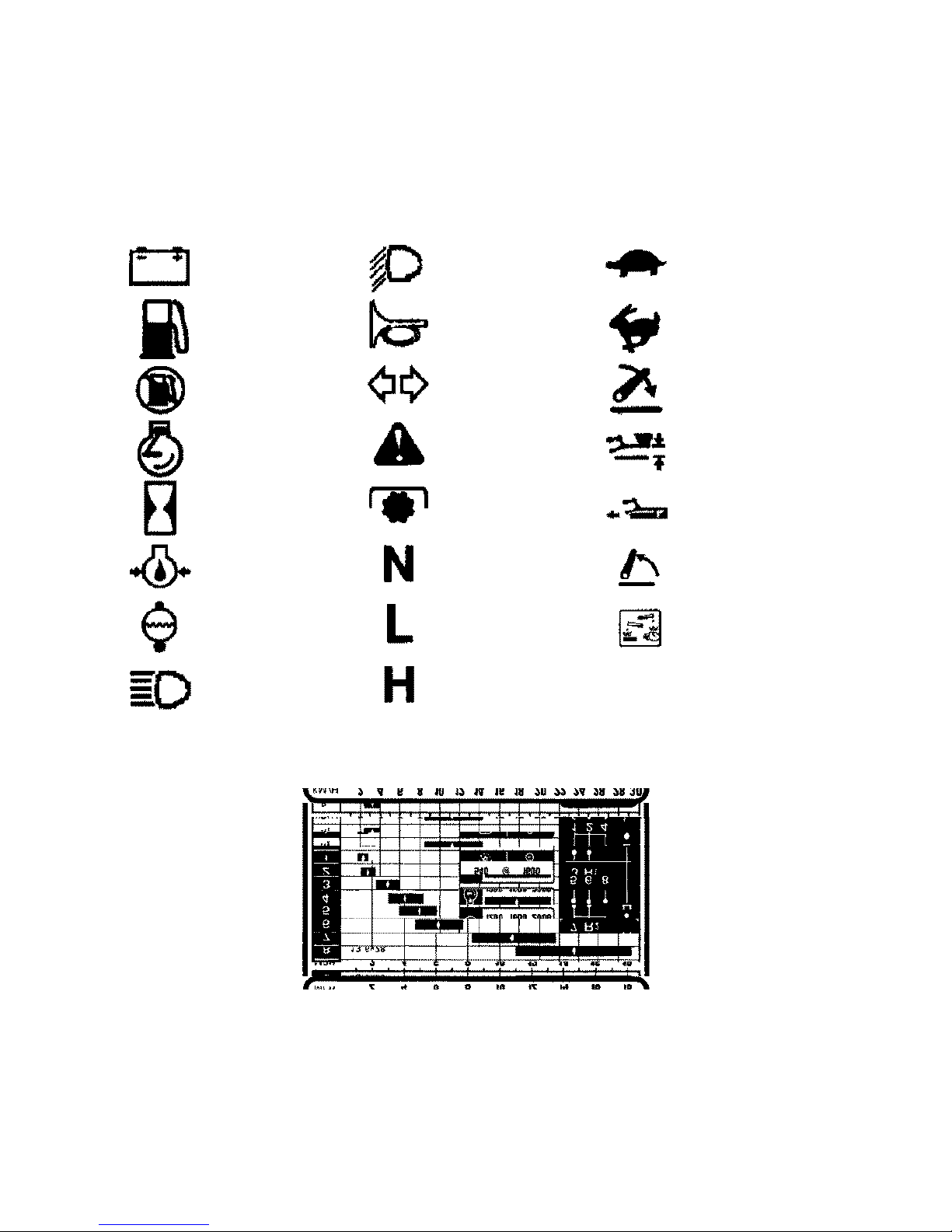
UNIVERSAL SYMBOLS
As a guide to the operation of your tractor, various universal symbols have been utilized on the instruments,
controls, switches and fuse box. The symbols are shown below with an indication of their meaning.
Alternator/Dynamo
Charge
Fuel level
Fuel shut-off
Engine speed
(rev/min × 100)
Hours recorded
Engine oil pressure
Engine coolant
temperature
Headlight
main beam
Headlight dipped
beam
Horn
Turn Signals
Warning!
P.T.O.
Transmission in
neutral
Low transmission
range
High transmission
range
Slow or low setting
Fast or high setting
Linkage lower
Position Control
Draft Control
Linkage raise
Warning! Corrosive
substance
The decal shown above is similar to that fitted next to the instrument panel of your tractor and graphically illustrates
the approximate tractor road speed at three alternative engine speeds. The decal also shows the engine speed at
which P.T.O. speed of 540 RPM is obtained. Accurate road speed charts are provided at the end of Section C.
ix
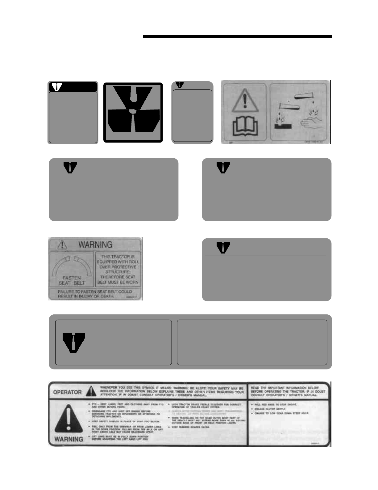
SAFETY SYMBOLS
x
CAUTION
DO NOT OPERATE
UNTILL YOU READ THE OWNERS MANUAL
IF YOU DID NOT RECEIVE A COPY ONE MAY BE OBTAINED FROM
YOUR AUTHORISED DEALER
l
Pull only from drawbar. Pulling
from other points can cause rear
overturn.
l
Do not operate with unshielded PTO.
l
Disangage PTO and stop engine before
servicing tractor or implements or
attaching and detaching implements.
l
Position drawbar at 14" from end of
PTO shaft to drawbar hole for 540 RPM.
l
When towing equipment use a safety
chain.
FAILURE TO FOLLOW ANY OF THE INSTRUCTIONS
ABOVE CAN CAUSE SERIOUS INJURY TO THE
OPERATOR OR OTHER PERSONS.
WARNING
WARNING
AVOID POSSIBLE INJURY
OR DEATH FROM A
MACHINE RUNAWAY
1. Do not start engine by shorting
across starter terminals.
Machine will statrt in gear and
move if normal starting circuitry is bypassed.
2. Start engine only from operators seat with transmission in
neutral or park.
NEVER start enigine while
standing on the ground.
CAUTION
AFTER FIRST HOUR OF OPERATION FRONT
AND REAR WHEEL LUG NUTS AND BOLTS
SHOULD BE CHECKED FOR PROPER
TORQUE - THERE AFTER CHECK DAILY.
82835415
WARNING
THE DIFFERENTIAL LOCK IS PROVIDED FOR USE ON SLIPPERY SURFACES, IT MUST NOT BE USED ON
THE ROAD.
WARNING
TO AVOID INJURY, KEEP
THIS GUARD IN PLACE
SAFETY INSTRUCTIONS
E2NN-94000R86-AA
82835419
11 78500 AA

CONTROLS,
INSTRUMENTS
and OPERATION
The following pages in this section detail the location and function of the various instruments, switches and controls
on your tractor. Even if you operate other tractors, you should read through this section of the Manual and ensure
that you are thoroughly familiar with the location and function of all the features of your new tractor. Do not start the
engine or attempt to drive or operate the tractor until you are fully accustomed to all the controls. It is too late to
learn once the tractor is moving. If in doubt about any aspect of operation of the tractor, consult your Authorized
Dealer. Reference to tractor models or equipment not available in your territory or to options or accessories not fitted
on your tractor should be ignored.
Particular attention should be paid to the recommendations for running-in to ensure that your tractor will give the
long and dependable service for which it was designed.
See Section B for the routine lubrication and maintenance requirements. The specification of your tractor will be
found in Section C.
SECTION A
1
OPERATOR’S SEAT
Before operating the tractor, it is important to adjust
the seat to the most comfortable position. See Figure 1
for details.
To achieve the optimum suspension setting, sit in the
seat and turn the suspension adjuster knob until the
weight indicators on the seat frame align.
Press down the horizontal travel adjustment lever and
move the seat forward or backward, as required. Further
seat travel is possible after loosening the two seat
mounting bolts that secure the seat base to the tractor.
Seat height is adjusted after loosening the two knobs
on both sides of the seat frame.
NOTE: Do not use solvents to clean the seat. Use
warm water with a little detergent added.
SEAT BELT, SAFETY FRAME OR ROLL BAR
(where fitted)
WARNING : Tractors equipped with a safety
frame or roll bar also have a seat belt fitted.
Always use the seat belt with a safety frame or roll-bar
installed. Do not use a seat belt if the tractor is not
equipped with a safety frame or roll bar.
To lengthen the belt, tip the buckle away from the belt
and pull on the buckle. With the belt fastened around
you, pull the free end of the belt until it is a snug fit.
The belt may be sponged with clean, soapy water. Do
1. Seat
1. Suspension adjuster knob
2. Weight indicators
3. Horizontal travel adjustment lever
4. Seat mounting bolts
5. Height adjustment knob
not use solvents, bleach or dye on the belt as a these
chemicals will weaken the webbing. Replace the belt
when it shows signs of fraying, damage or general wear.
If your tractor is fitted with a safety frame or roll bar, it
must be maintained in a serviceable condition.
If your tractor is fitted with a front end loader, it is
recommended that a canopy be fitted to protect the
operator from objects that may fall from the loader
bucket.
WARNING: Do not attach chains or ropes to
the safety frame or roll bar for pulling purpose since
the tractor may tip back-wards. Always pull from the tractor
drawbar. Be careful when driving through door openings
or under low overhead objects. Make sure that there is
sufficient overhead clearance for the roll bar.
INSTRUMENTS AND CONTROLS
The following text describes the various gauges,
switches and warning lights installed on your tractor,
See Figure 2A and 2B.
Tachometer
The tachometer indicates engine revolutions per minute.
Each division on the scale represents 100 rev/min.-eg.
with the needle indicating ‘20’ the engine is running at
2000 rev/min.
The yellow mark on the tachometer scale indicates the
engine speed at which the standard P.T.O. speed of
540 rev/min is obtained.
The tachometer also records the total number of hours
that the tractor has operated, based on an average
engine speed of 1600 rev/min. If the engine is run at a
speed lower than 1600 rev/min then the tachometer will
accumulate hours at a rate slower than real time. Higher
engine speeds will cause the tachometer to accumulate
hours at a rate faster than real time.
The hours recorded should be used as a guide to
determine hours servicing intervals. (see Section B of
this Manual).
Engine Coolant Temperature Gauge
The gauge indicates the temperature of the engine
coolant. If the needle enters the red area of the gauge
while the engine is running, stop the engine and
investigate the cause.
NOTE : When the key-start switch is turned off, the
gauge needle will assume a random position.
CONTROL, INSTRUMENTS AND OPERATION
2
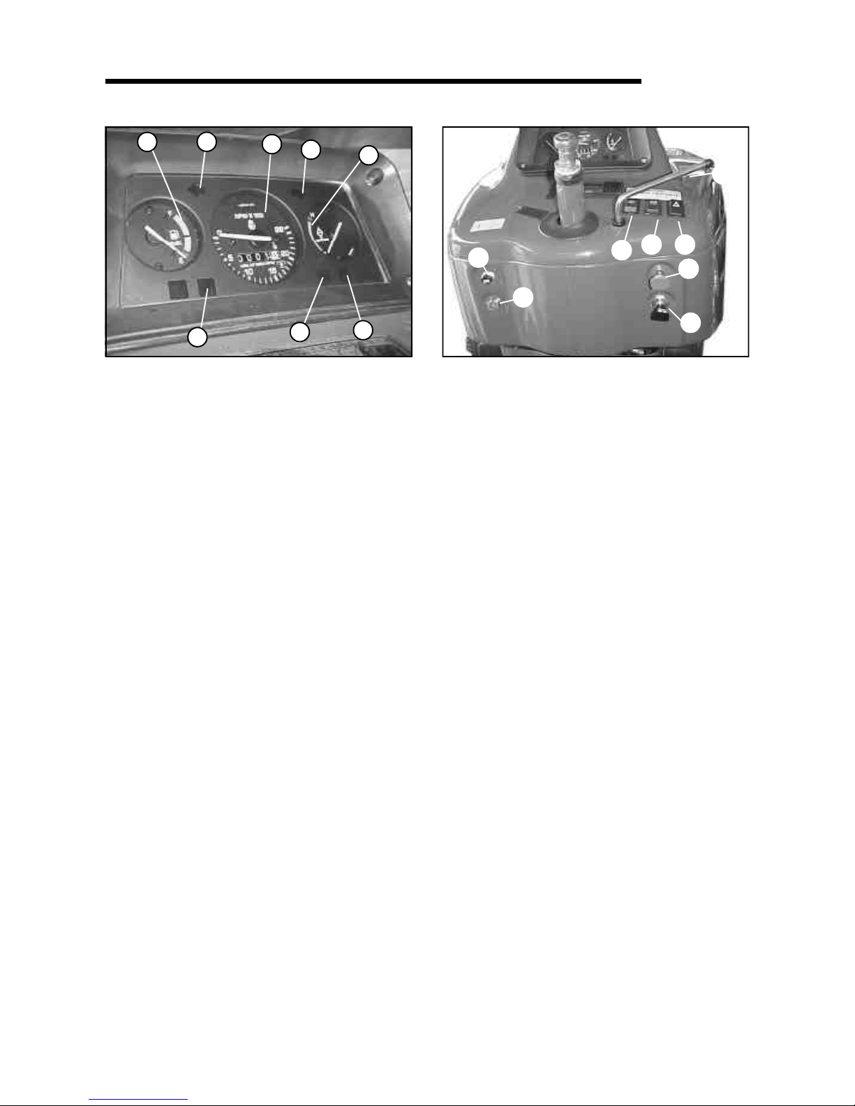
2A. Single Instrument Cluster
1. Tachometer
2. Engine coolant temperature gauge
3. Engine Oil Pressure Warning Light
4. Fuel Gauge
5. LH Turn Signal Indicator
6. RH Turn Signal Indicator
7. Battery Charging Indicator
8. Hazard Warning Light Switch
9. Air Restriction Warning Light
10. Engine Stop Control
11. Tractor Light Switch
12. Key Start Switch
13. Horn Switch
14. Hand Throttle
15. Turn Signal Indicator Switch
16. Plough Lamp Switch
Engine Oil Pressure Warning Light
The red warning light on the instrument panel indicates
low engine oil pressure and should extinguish immediately
after the engine is started, and is only operative with the
key start switch in the ‘ON’ position.
NOTE : If the light comes on while engine is running,
stop the engine immediately and investigate the cause.
The light indicates low oil pressure and is not an indication
of oil level. The engine oil level must still be checked
daily by means of the dipstick.
Hand Throttle
With the engine running, pull the throttle lever rearwards
to progressively increase engine speed. Push the throttle
lever forward to decrease the engine speed.
Hazard Warning Light Switch
Press the switch to operate both turn signals
simultaneously. The switch, which is internally
illuminated, will flash in unison with the turn signals
and the turn signal indicator lights on the instrument
panel.
Indicator Ligthss
The upper indicator light of the pair will illuminate when
headlamp main beam is selected. When either of the turn
signal is operated, the lower indicator light will flash in
unison with the turn signals.
In some territories, where only single beam (dipped
beam) headlamps are fitted, the upper indicator light
will flash in unison with the turn signals when either of
the turn signal is operated. If, however, the tractor is
also equipped with a 7 pin rear trailer socket, the lower
indicator light will flash in unison with the turn signals
of the trailer when either of the turn signal is operated.
The turn signal indicator lights will also flash in unison
with the turn signals whenever the hazard switch is
operated.
NOTE : Please check with your Authorized Dealer on
which system is fitted on your Tractor.
Tractor Lights Switch
The lights switch is of the push-pull type and has three
positions:
Fully in : lights OFF
Midway : side, rear and instrument lights ‘ON’
Fully out : side, rear, instrument and headlights ‘ON’
Engine Stop Control
Pull the stop control knob fully out and hold it in that
position to cut off the fuel supply to the injectors and
stop the engine. The knob must be pushed fully in before
restarting the engine.
SECTION A
3
2B. Instrument Panel
(Steering wheel removed)
4
7
5
3
9
2
6
1
10
11
12
13
14
15
16
8

4
Key-Start Switch
The key operated switch actuates the starting motor.
See ‘Starting The Engine’ for the correct operating
procedure.
Road Speed Decal
The decal which is also illustrated on Page IX, shows the
approximate tractor speed in all gear ratios. Accurate road
speed charts are provided at the end of section C.
Charging Indicator
The red warning light on the instrument cluster indicates
that the alternator is not charging the battery and should
extinguish when the engine speed is increased above
idle.
Fuel Gauge
The gauge indicates the level of fuel in the tank and is
only operative with the key-start switch in the ‘ON’
position.
NOTE : When the key-start switch is turned off the
gauge needle may assume a random position and may
indicates a fuel level greater than the true level. Always
check the fuel level with the key-start switch on.
Air Restriction Warning Light (where fitted)
When this lamp lights up, clean or replace the outer
element of dryair cleaner. If light comes on during tractor
operation when replacement of element is not
immediately possible, just clean the element and reduce
the engine speed so on to prevent the lamp from lighting.
Seven-Terminal Trailer Socket (where fitted)
This socket allows lights, turn signals and other electrical
equipment on a trailer or impliment to be connected.
This is fitted at the rear of driver’s seat.
Always use additional lighting on the mounted implement
if this conceals the turn signals and other lights at the
rear of the tractor.
CONTROL, INSTRUMENTS AND OPERATION
STARTING THE ENGINE
A five-position key-start switch is installed on all the
tractors. For starting in temperatures down to –180C
(00F) the thermostart option may also be installed,
Basically the thermostart consists of an electrically
heated element in the air in taken manifold which, when
operated, ignites a measure of diesel fuel and
introduces it into the combustion chamber. With the
thermostart installed, all the five positions of the
keystart switch are connected as shown in Figure 3.
However, if the automatic thermostart is not installed,
the starting motor operates at position (4) while as
position (5) is left unconnected (see Figure 3).
IMPORTANT : Never push or tow the tractor to start
the engine. Doing so may overstress the drive train.
NOTE: A safety start switch prevents operation of the
starting motor unless the transmission range lever is in
the neutral (N) position.
Before starting the engine, always carry out the following
procedure:
l Sit in the driver’s seat and ensure that the parking brake
latch is firmly applied.
l Push the stop control knob fully in.
l Ensure that both gearshift levers are in neutral and
that the P.T.O. lever is in the disengaged position.
l Move both hydraulic lift control levers fully forward.
l Place the remote control valve levers in neutral.
WARNING : Start the tractor only from the driver’s
seat. If the key-start switch is bypassed, the
engine may start inadvertently with a gear selected and
cause sudden and unexpected movement of the tractor
or a tractor runaway. Wear eye protection when starting
the tractor with jump leads or when charging the battery.
For standard tractors (without automatic
thermostart)
l Open the hand throttle halfway, depress the clutch
to ease the load on the starter motor and turn the
key-start switch fully clockwise to position (4) to
operate the starting motor. Crank the engine until it
starts but do not operate the starting motor for more
than 40 seconds and then allow the key to return to
position (3).
l Return the throttle to the idle position and check that
all warning lights extinguish and gauge readings are
normal.
Connection Wire Colour
1. Ground Brown
2. Parking RH Grey-Red
3. Turn singal LH Black-White
4. Brake light Red-White
5. Turn signal RH Black-Green
6. Parking LH Grey-Red
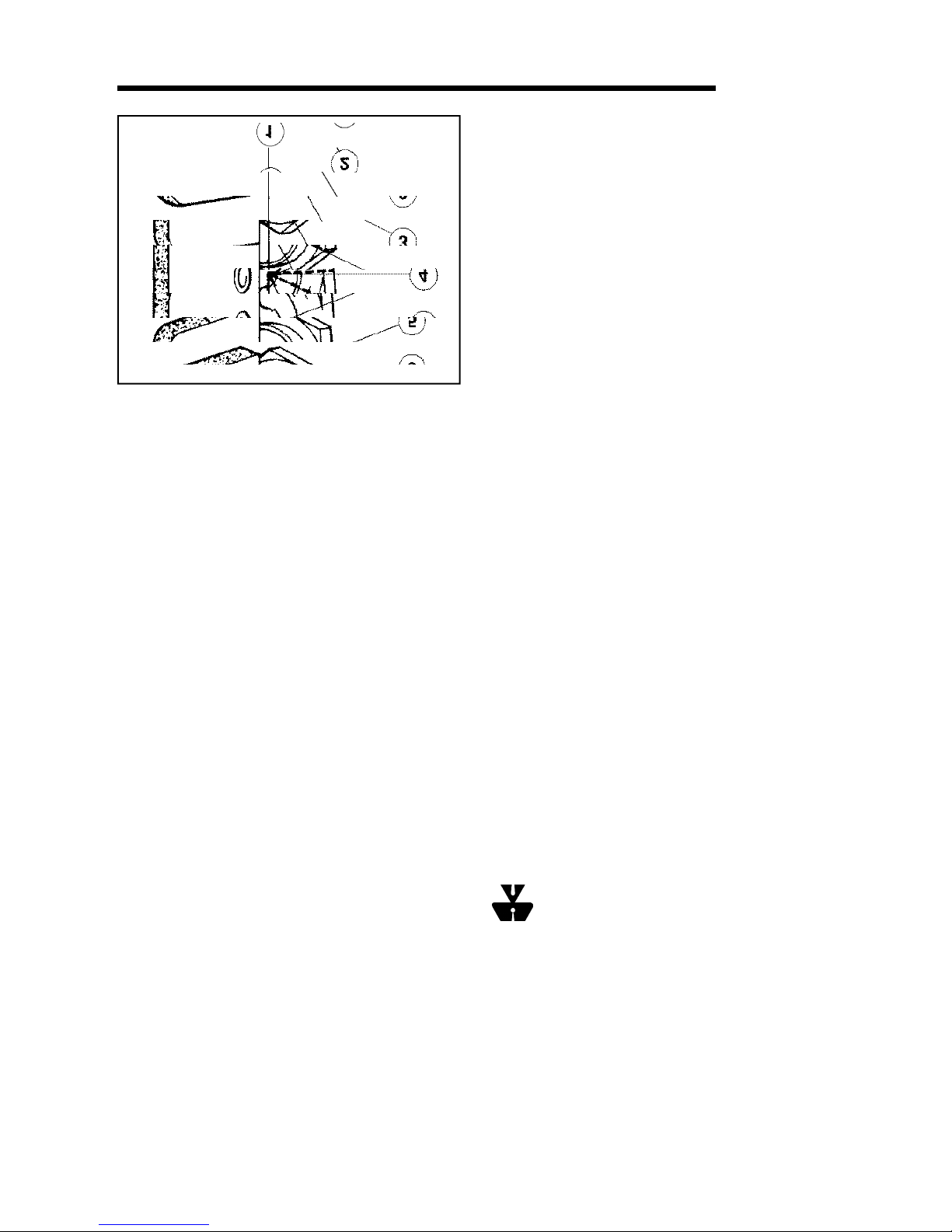
3. Key-start Switch
1. Electrical equipment ‘OFF’
2. Accessories ‘ON’
3. Warning lights and instruments ‘ON’
4. Thermostart heater ‘ON’ (where fitted), or
Starting motor operates (where thermostart is
not fitted).
5. Starting motor operates (where thermostart is
fitted), or
Unconnected (where thermostart is not fitted).
For tractors fitted with automatic
thermostart:
l In warm weather, or when the engine is hot, depress
the clutch and turn the keystart switch fully clockwise
to position (5). Operate the starting motor until the
engine starts or for a maximum of 40 seconds and
then allow the key to return to position (3).
l In cold weather with the engine cold, depress the
clutch and turn the key-start switch to position (4),
hold for 20-30 seconds and then turn fully clockwise
to position (5). Operate the starter until the engine
starts or for a maximum of 30 seconds.
l Return the throttle to the idle position and check
that all warning lights extinguish and gauge readings
are normal.
NOTE : If the engine fails to start, repeat the procedure,
after waiting for 1-2 minutes. If the thermo-start is fitted,
the key should be held at position (4) only for 7-10 seconds
when attempting to restart the tractor.
STARTING THE TRACTOR WITH JUMP LEADS
If it is necessary to use jump leads (booster cables) to
start the tractor, proceed as follows:
l Connect one end of the red jump lead to the tractor
battery positive (+) terminal and the other end to
the auxiliary battery positive (+) terminal.
l Connect one end of the black jump lead to the
auxiliary battery negative (-) terminal and the other
end to a suitable projection on the tractor engine
block. Follow the starting procedure previously
described.
l When the engine starts allow it to run at idle speed,
turn on all electrical equipment (Lights etc.) then,
disconnect the jump leads in the reverse order to
the connecting procedure. This will help protect the
alternator from possible damage due to extreme load
changes.
NOTE : When using an auxiliary battery to start the
engine, ensure that the polarity of the jump leads is correct
- positive to positive, negative to negative otherwise
the alternator may be damaged.
STOPPING THE ENGINE
To stop the engine, carry out the following procedure:
l Sit in the driver’s seat and close the throttle.
l Ensure that the parking brake latch is firmly applied.
l Ensure that both gearshift levers are in neutral and
that the P.T.O. lever is in the disengaged position.
l Pull the stop control knob fully out and turn the key-
start switch off.
l Move the hydraulic lift control levers fully forward to
lower all hydraulic equipment to the ground.
l Move the remote control valve levers fully forward
and then fully rearward before placing them in neutral
position.
WARNING : Check the area beneath the
equipment to ensure that no injury or damage will
be caused when equipment is lowered.
PARKING BRAKE
To parking brake consists of a latch that is used to secure
the foot brakes in the applied position. (See Figure 4).
SECTION A
5
4. Parking Brake
1. T-handle
To operate the parking brake, lock the brakes together
(see the following text titled ‘Foot-brakes’). Apply the
foot brakes, pull up the T-handle and rotate one quarter
turn. To free the parking brake, rotate the T-handle one
quarter turn and release. Momentarily depress the foot
brakes to disengage the ratched. In Figure 4, the parking
brake is shown in the applied position.
IMPORTANT : Ensure that the parking brake is fully
released before driving off.
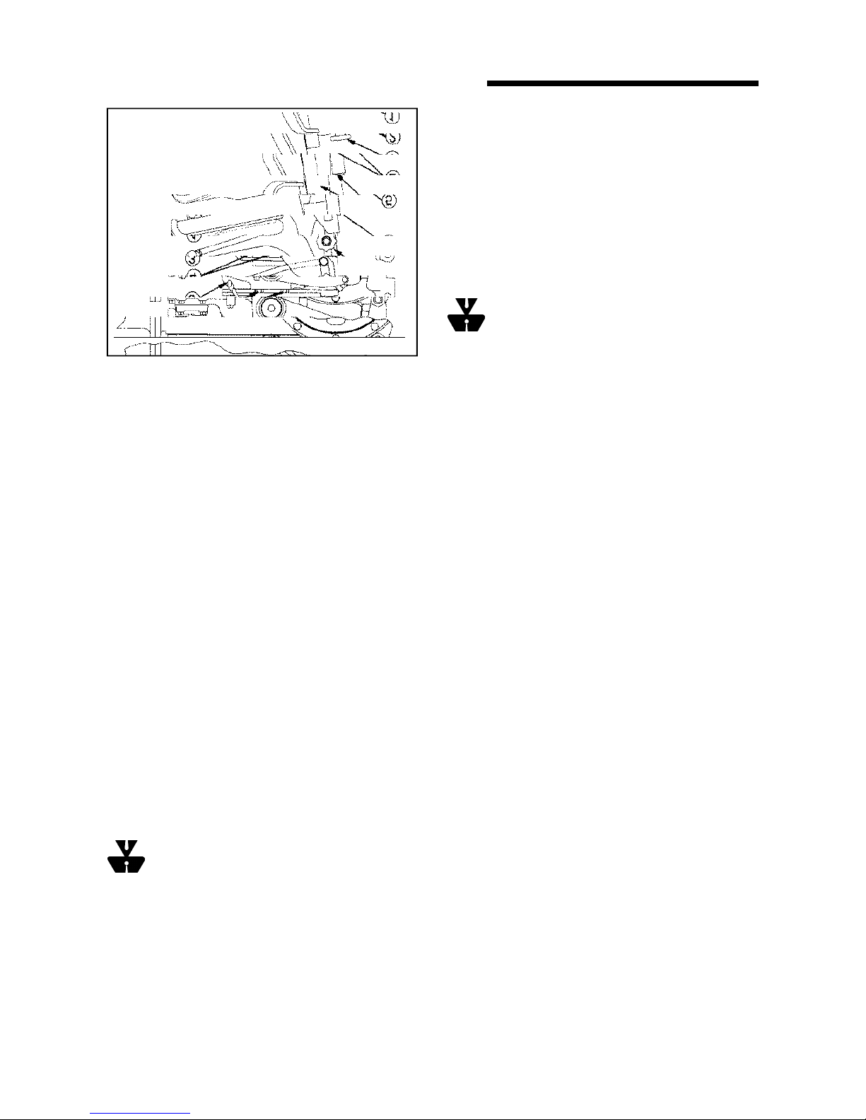
FOOT CONTROLS
For details of foot operated controls, refer to Figure 5
and the following text.
Foot Brakes
The foot brake pedals, Figure 5, activate the rear wheel
brakes and may be operated independently, to aid
turning in confined spaces or together for normal
stopping. When operating in the field, the brake pedals
may be unlocked. However, due to the close proximity
of the pedals to one another, it is still possible to apply
both brakes together, when required.
WARNING : For your safety, always lock the
brake pedals together when travelling at
transport speeds, or on a highway or if a trailer is
attached. To lock the pedals together, slide the latch (5)
across to engage in the hole in the underside of the
right-hand pedal, as shown.
Foot Accelerator
The foot accelerator, Figure 5, may be used
independently of the hand throttle to control the speed
of the tractor. It is recommended that you use the foot
accelerator when driving on the highway.
NOTE : When it is required to use the foot accelerator,
set the hand throttle to the idle position (fully forward).
Differential Lock
In field conditions including wheel slip, hold down the
differential lock pedal, Figure 5, until the lock is felt to
engage. The lock will automatically disengage when
traction at the rear wheels equalizes.
If conditions cause a rear wheel to spin at speed, reduce
the engine speed to idle before engaging the differential
lock.
WARNING : Never engage the differential lock
at speeds above 5 mph (8 kmph) or when turning
the tractor. When engaged, the lock will prevent the
tractor from turning.
Clutch
When the clutch pedal, Figure 5, is depressed the drive
between the engine and transmission will be disengaged.
Use the clutch pedal to transfer engine power smoothly
to the driving wheels when moving off from a standstill.
Always depress the clutch pedal to engage or disengage
a gear ratio or when operating transmission P.T.O. or
live P.T.O. (see Power Take Off in this section of the
Manual)
NOTE : Avoid resting your foot on the clutch pedal
when operating the tractor. Such action will lead to early
clutch failure.
5. Foot Controls
1. Brake pedals
2. Foot accelerator
3. Differential lock pedal
4. Clutch pedal
5. Locking latch
6
CONTROL, INSTRUMENTS AND OPERATION

TRANSMISSION
The transmission is of the constant mesh type and has
eight forward and two reverse speed ratios.
WARNING : To prevent inadvertent tractor
movement, avoid accidental contact with the
gearshift levers. Always stop the engine, firmly apply
the parking brake and place both gearshift levers in
neutral before dismounting from the tractor. A safety
switch prevent operation of the starting motor unless
the right-hand lever is in the neutral (N) position.
The gearshift levers protrude from the center of the
transmission, beneath the steering wheel.
The left-hand gearshift lever (main) is used to select
any one of four forward or one reverse gear ratio. The
right-hand lever (range) is used to select the high (H) or
low (L) range which has the effect of doubling the number
of available gear ratios. Stop the tractor and fully
depress the clutch before moving either of the gear
levers. See Figure 6 for the gear shift positions.
IMPORTANT : When towing the tractor, it is essential
that the transmission main (right-hand) lever is kept in
the neutral (N) position. Non compliance may result in
damage to transmission components.
Avoid overloading the engine. Operating in too high a
gear under heavy load may cause excessive engine
overloading. Overloading occurs when the engine will
not respond to a throttle increase.
Use the lower gear ratios when pulling heavy loads and
avoid continuous operation at constant engine speeds.
Operating the tractor in too low a gear with a light load
and high engine speed will waste fuel. You will save fuel
and minimize engine wear by selecting the correct gear
ratio for each particular operation.
Check the instruments frequently and keep the radiator
and various oil reservoirs filled to the recommended
levels.
POWER TAKE-OFF (P.T.O.)
The power take-off (P.T.O.) on your tractor transfers
engine power directly to mounted or trailed equipment
via a splined shaft at the rear of the tractor.
The P.T.O. shaft is a 6-spline, 1.375 in (34.9 mm)
diameter shaft designed for 540 rev/min operation, the
speed at which most P.T.O. actuated equipment are
designed to run.
To obtain 540 rev/min at the P.T.O., set the tractor engine
speed to 1600 rev/min if your tractor is equipped with
transmission P.T.O., or 1800 rev/min for live PTO models.
For most P.T.O. operations the ground speed of the tractor
is controlled by selection of the appropriate gear ratio
while maintaining the correct P.T.O. speed by using the
throttle.
Attaching P.T.O. Driven Equipment
WARNING : Before attaching, detaching or
working on P.T.O. driven equipment, the following
precautions must be taken :* Firmly apply the parking brake.
* Ensure that both gearshift levers are in neutral and
that the P.T.O. lever is in the disengaged position.
* Stop the engine.
* Ensure that the P.T.O. shaft has stopped turning.
6. Gear Shift Lever Positions
H = High Range
L = Low Range
N = Neutral
R = Reverse
SECTION A
Range lever Main gear shift lever
RUNNING-IN-PROCEDURE
Your new tractor will provide long and dependable service
if given proper care during the first 50 hours running-inperiod and if serviced at the recommended intervals.
Avoid prolonged operation at either high or low engine
speeds without a load on the engine.
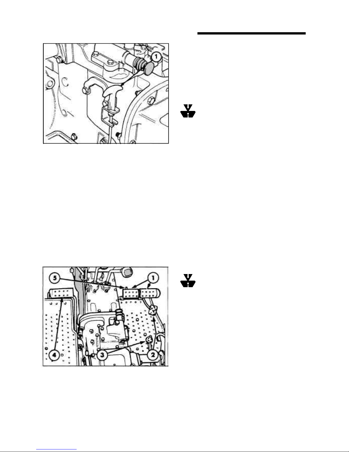
7
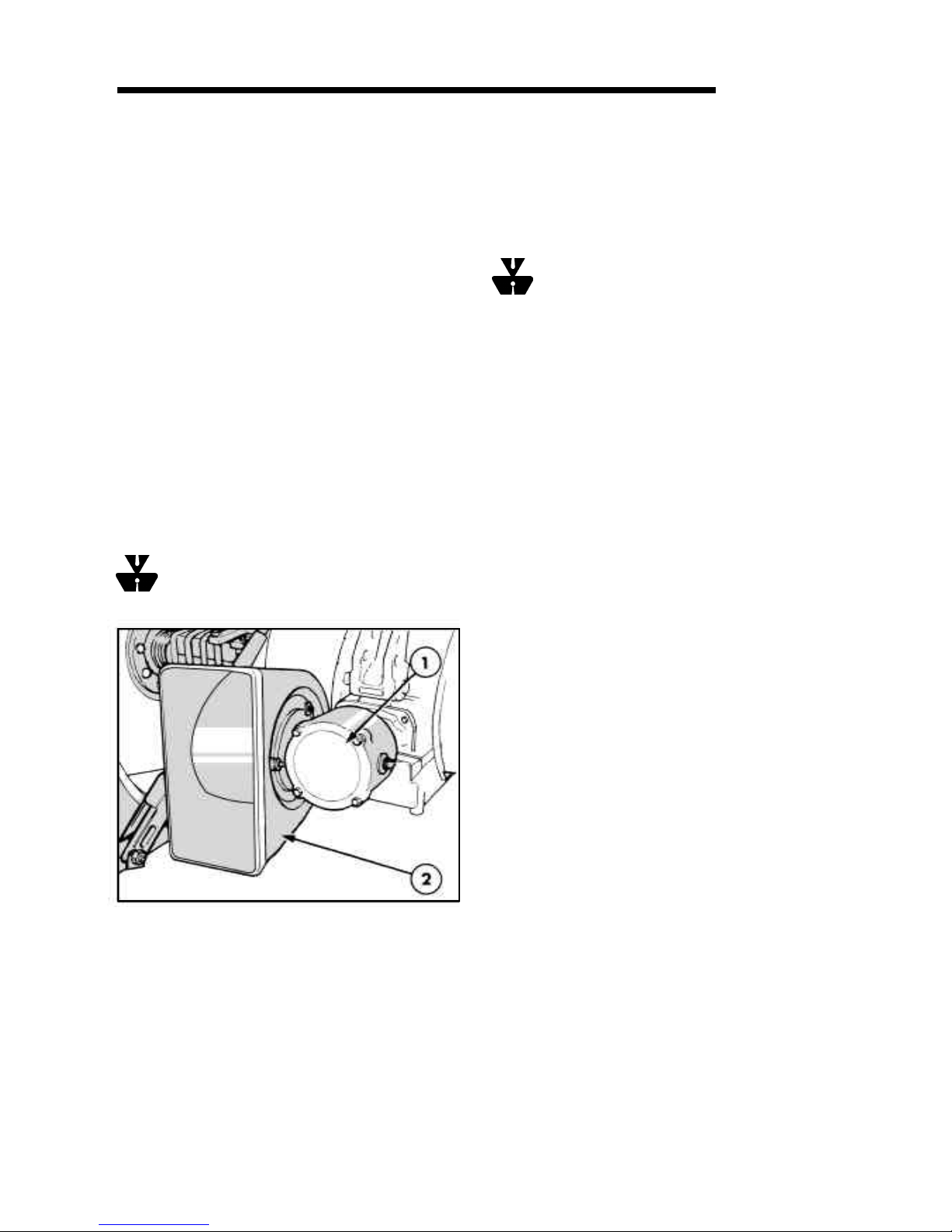
To connect P.T.O. driven equipment to the P.T.O. shaft,
remove the guard (where fitted) which is secured to the
rear axle center housing by a linch pin, as shown in
Figure 7. Unscrew and remove the P.T.O. cap and store
in the toolbox. Attach the implement to the P.T.O. shaft
and reinstall the guard.
WARNING : The guard serves as a support
for drive line shields used with Pull-type P.T.O.
driven equipment and also provides you safety.
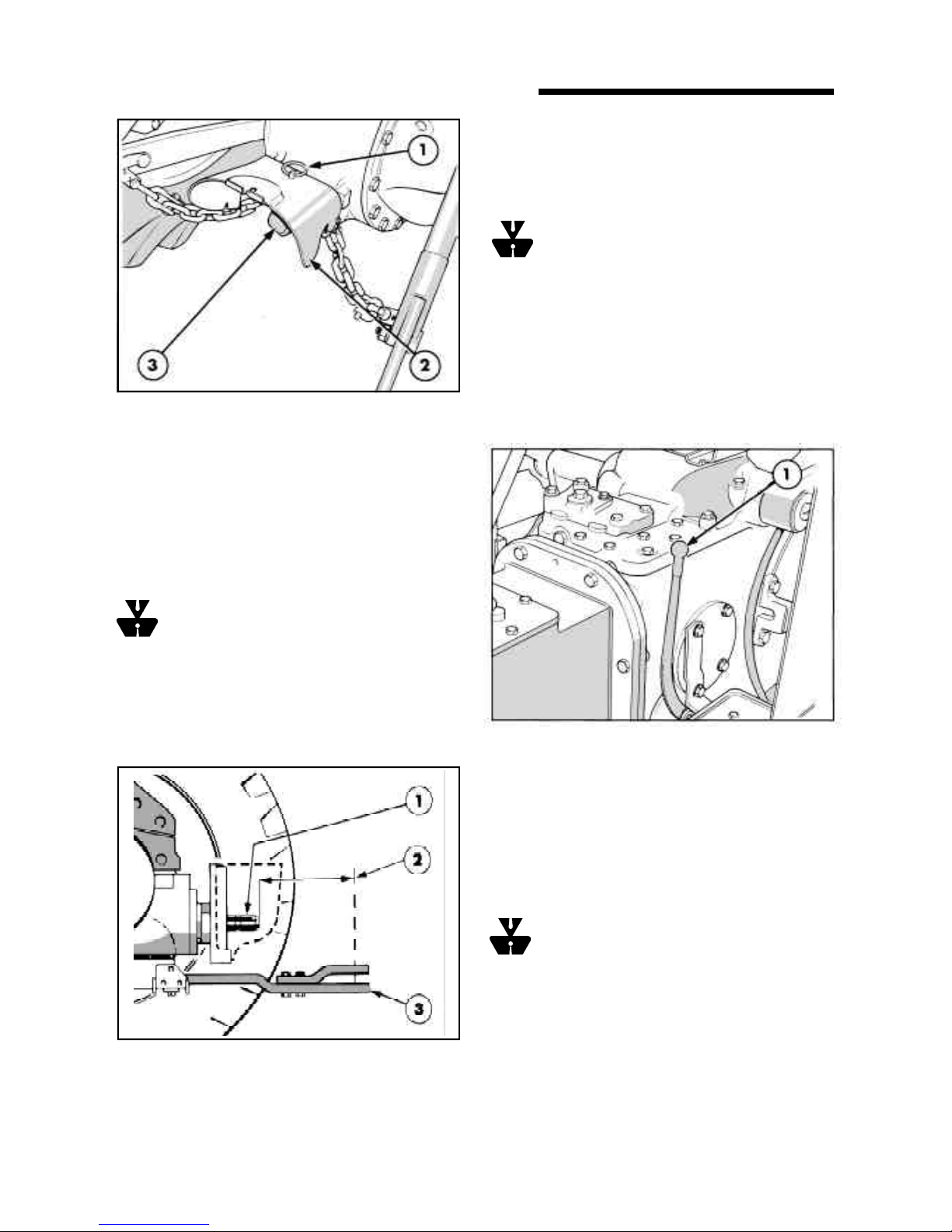
If P.T.O. driven equipment is attached to the drawbar
then the drawbar should be set to the extended position
so that the horizontal distance between the end of the
P.T.O. shaft and the pin hole in the end of the drawbar is
at least 14.9 in (378 mm.) See figure 8.
IMPORTANT : After attaching mounted equipment
carefully raise and lower them using Position Control
Lever and check clearances and P.T.O. shaft slide range
/ articulation. When attaching trailed equipment, ensure
the drawbar is correctly set.
WARNING : Do not approach or work on the
P.T.O. shaft or equipment with the P.T.O. in
motion. Block all four wheels when carrying out
stationary P.T.O. work.
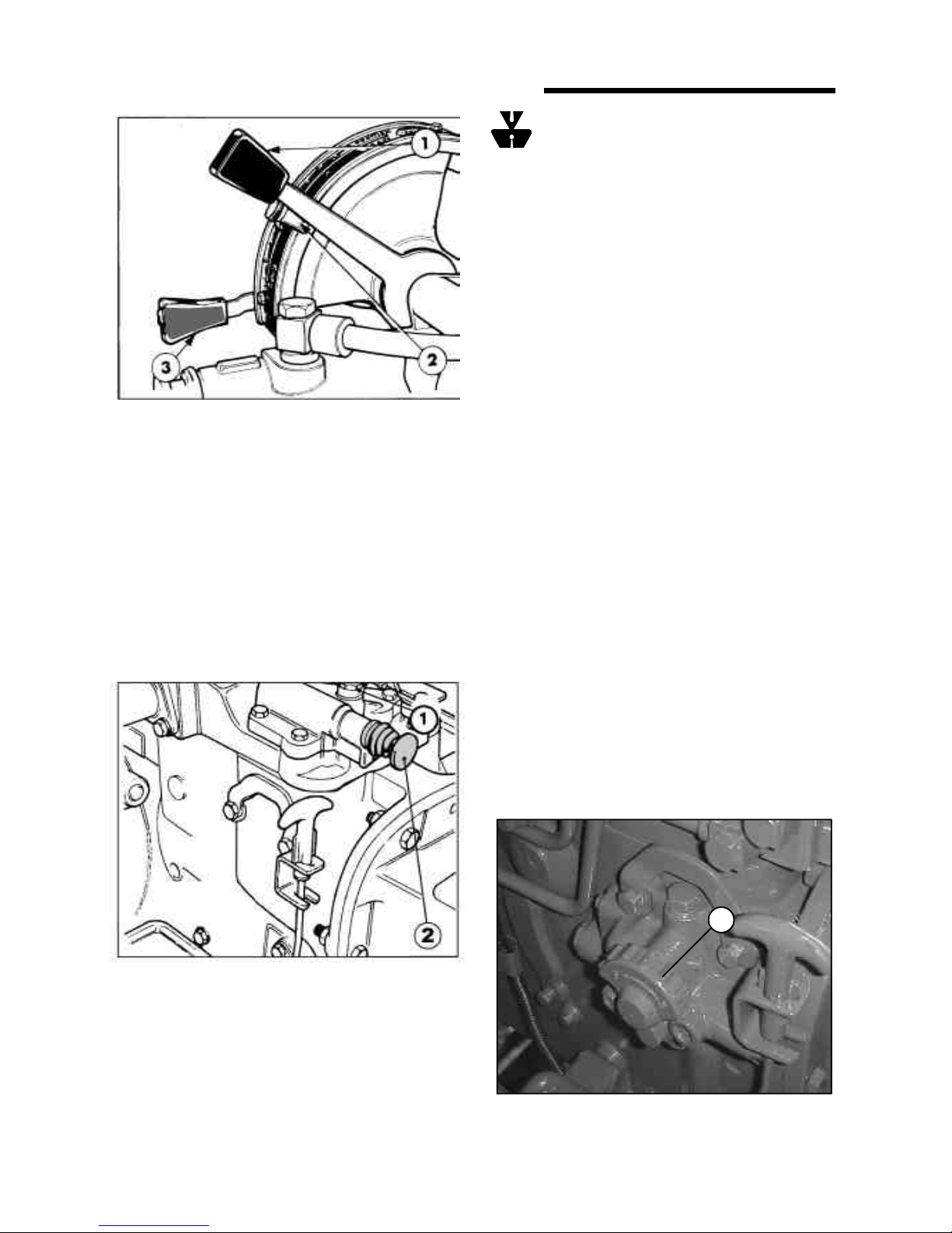
OPERATING THE P.T.O.
Transmission P.T.O. (where fitted)
To operate transmission P.T.O., start the engine, fully
depress the clutch pedal and pull the P.T.O. selector
lever, Figure 9, rearwards. Set the engine speed to 1600
rev/min. then release the clutch pedal.
7. Power Take-Off
1. Linch pin
2. Guard
3. P.T.O. cap
8. Drawbar setting
1. P.T.O. output shaft
2. Horizontal distance - shaft to hitch pin
3. Drawbar
9. P.T.O. Selector
1. P.T.O. selector lever
Transmission P.T.O. may be engaged or disengaged
whether the tractor is moving or stationary. When
stopping the tractor, the action of depressing the clutch
pedal will stop rotation of the P.T.O. output shaft.
IMPORTANT : Always depress the clutch pedal before
engaging or dis-engaging the P.T.O. to prevent damage
to P.T.O. components.
WARNING : To avoid inadvertent movement
of the implement, disengage the P.T.O. after each
use.
Live PTO (where fitted)
Live P.T.O. operates in a similar manner to Transmission
P.T.O. except that a two stage clutch permits the tractor
to be stopped while allowing the P.T.O. shaft to continue
turning. With the clutch pedal fully depressed neither
the tractor nor the P.T.O. shaft is operable.
8
CONTROL, INSTRUMENTS AND OPERATION
To operate Live P.T.O., start the engine, fully depress
the clutch and pull the P.T.O. selector lever, Figure 9,
rearwards to engage the P.T.O.
Set the engine speed at 1800 rev/min and release the
clutch pedal to the halfway position to actuate the P.T.O.
output shaft.
With a gear selected, fully release the clutch pedal to
run the tractor.
To stop the tractor, depress the clutch pedal to the midposition and to stop the P.T.O. output shaft depress the
pedal fully.
BELT PULLEY (where provided)
The belt pulley, which is driven by the P.T.O . output
shaft, should be installed as shown in Figure 10.
Prior to installation, remove the drawbar and drawbar
hanger to provide the maximum clearance for the drive
belt.
To install the belt pulley, remove the P.T.O. safety cap
and guard and the four bolts securing the check chain
brackets to the rear axle center housing. Install the belt
pulley on the P.T.O. shaft using the four bolts provided.
WARNING : To avoid injury, always use a belt
guard whenever using the belt pulley.
l Hang a chain or lean an iron bar against the tractor
to earth static electricity.
l Start the engine and engage the P.T.O. The
recommended belt speed is 3000-3200 ft/min
(15.3-16.3 m/sec). To obtain this speed set the
engine speed at 2000 rev/min.
WARNING: Never attempt to re-fit or adjust a
belt in motion. Never approach a moving belt
when wearing loose clothing. Apply the parking brake,
place both gearshift levers in neutral and block all four
wheels before operating the belt pulley.
HYDRAULIC SYSTEM
Your tractor is equipped with a hydraulic system
providing accurate and sensitive control over a wide
range of operating conditions.
Two distinct systems are incorporated
1. Upper Link Draft Control.
2. Position Control.
The type of control selected will depend on the type of
implement in use and the operating conditions.
Draft Control is most suitable for mounted
implements operating in the ground. Changes in the
working depth or soil resistance cause the draft loading
on the implement to increase or decrease. This change
in draft loading is sensed through the top link of the
three-point linkage and the hydraulic system responds
by raising or lowering the implement to restore the draft
loading. In this way a uniform draft load is maintained
on the implement. The system responds to both upper
link compression and tension loads and is, thus,
described as a double-acting system.
Position Control provides accurate and sensitive
control of implements such as sprayers, rakes, mowers,
etc., that operate above the ground. Position Control
would not normally be used with ground engaging
equipment unless it is essential to maintain a constant
depth regardless of the draft load.
The tractor has a dual lever system, i.e., separate levers
for Draft and Position Control functions. See Figure 11.
The Draft and Position Control levers are used to raise
or lower the three-point linkage (and implement) to the
required height or working depth.
To Operate the Belt Pulley
l Fully raise and secure the lower links.
l Align the tractor with the equipment to obtain full width
contact on both pulleys without the belt contacting any
other part of the tractor or equipment.
l Apply the parking brake and block all wheels to prevent
tractor movement due to vibration.
SECTION A
10. Belt Pulley
1. Belt pulley
2. Belt guard
9
WARNING: Do not transport or attach
equipment when the hydraulic system is in Draft
Control Use position Control for these operations.
Always lower hydraulic equipment to the ground before
stopping the tractor.
Draft Control Operation
Move the Draft Control Lever in the quadrant to find the
point near the center where the lift links neither raise
nor lower. This is the neutral point.
Lower the implement into work using the Draft control
Lever. Push the Lever forward to increase the draft
loading. Pull rearwards to reduce the draft loading. In
most circumstances, forward movement of the Draft
Control Lever will increase implement depth and
rearward movement will reduce the depth.
Once set, the tractor hydraulic system will automatically
adjust the implement depth to maintain an even pull on
the tractor and so reduce wheel slip to a minimum.
When lowering the implement into work push the Draft
Control Lever down to the bottom of the quadrant to
ensure positive engagement of the implement in the
ground then immediately raise the Draft Control Lever
until the required implement depth is achieved.
When the required implement working depth has been
established, set the adjustable stop adjacent to the Draft
Control Lever to locate the position for repeated use.
The Draft Control Lever may be eased sideways to
bypass the adjustable stop, if required.
A pressure sensitive feathering valve, installing within
the hydraulic system, automatically regulates the
hydraulic oil flow to give smoother response to draft
signals when using soil engaging implements. In
addition, some models have a manually operated flow
control valve fitted to regulate the rate of correction of
the hydraulic system.
CONTROL, INSTRUMENTS AND OPERATION
In order to operate the hydraulic three-point linkage the
auxiliary services control valve knob (if fitted) must be
correctly set. The auxiliary services control valve (A.S.C.
valve) directs oil to the three-point linkage, to external
cylinders or both together, as may be required.
To operate the three-point alone push the A.S.C. valve
knob fully in (rearward). See figure 12.
Pull the A.S.C. valve knob fully out (forward) to operate
external services only.
11. Hydraulic Control
1. Draft Control lever
2. Adjustable stop
3. Position Control lever
The midway position is selected to operate the three point
linkage and external cylinders simultaneously. See
OPERATING REMOTE CYLINDERS WITH THE A.S.C.
VALVE in this section of the manual.
10
12. A.S.C. Valve (where fitted)
1. A.S.C. tapping
2. A.S.C. valve knob
13. Flow Control Valve
1. Flow control valve rocker
1
Tilt the Flow Control Valve Rocker, Figure 13, rearward
for the maximum rate of correction and forward for the
minimum correction rate. The rate of oil flow (correction)
of the hydraulic system is infinitely variable between
these two points.
Pull the Draft Control Lever to the top of the quadrant to
override the Flow Control Valve and raise the implement
quickly.
NOTE: When operating in Draft Control, the Position
Control Lever, Figure 11, should normally be at the
bottom of the quadrant. However, the Position Control
Lever may be used in conjunction with Draft Control to
limit the maximum depth of correction to achieve a more
even depth of cultivation in fields with widely varying
soil conditions.
When grading and backfilling with light equipment, such
as a rear blade, it may be desirable to prevent the blade
from “diving”. This is accomplished by using the Position
Control Lever in conjunction with the Draft Control Lever.
See “Draft Control Operation with Position Control” on
this page.
Position Control Operation
Set the required implement height/depth using the
Position Control Lever, Figure 11. Pull the Lever Back
to raise the implement height/depth using the Position
Control Lever. Pull the lever back to raise the implement,
push forward to lower. Implement height/depth is relative
to the position of the Lever in the quadrant.
When the required implement working height/depth has
been established, set the adjustable stop adjacent to
the Position Control Lever to locate the position for
repeated use. The Lever may be eased sideways when
it is required to by pass the adjustable stop.
The adjustable stop is reversible after loosening the
central clamp screw so that it may also be used when
operating in Draft Control.
When operating in Position Control it is of no advantage
to restrict the oil flow in the hydraulic system. However,
the manual flow control valve (where fitted) may be used
to reduce the rate of lift of the three-point linkage, if
required. To reduce the rate of lift, tilt the Flow Control
Valve Rocker, Figure 13, forward. Tilt the Rocker rearward
to increase the rate of lift.
IMPORTANT : When transporting equipment on the
three-point linkage set the adjustable stop to maintain
the Position Control Lever in the raised position. This
will prevent accidental movement of the lever which
could result in attached equipment lowering and
becoming damaged or damaging the road surface.
Draft Control operation with Position Control
Position Control may be used together with the Draft
Control as follows:
Set the Position Control Lever at the maximum desired
implement depth. The hydraulic system will not lower
the implement below this depth. This will also prevent
“diving” which may be encountered will light equipment,
such as a rear blade, when grading or backfilling.
Adjust the Draft Control Lever for the maximum required
draft load (pull).
The hydraulic lift system will now provide normal draft
response within the range set by the Position Control.
This adjustment provides a more uniform depth while
maintaining an even pull in widely varying soil
conditions.
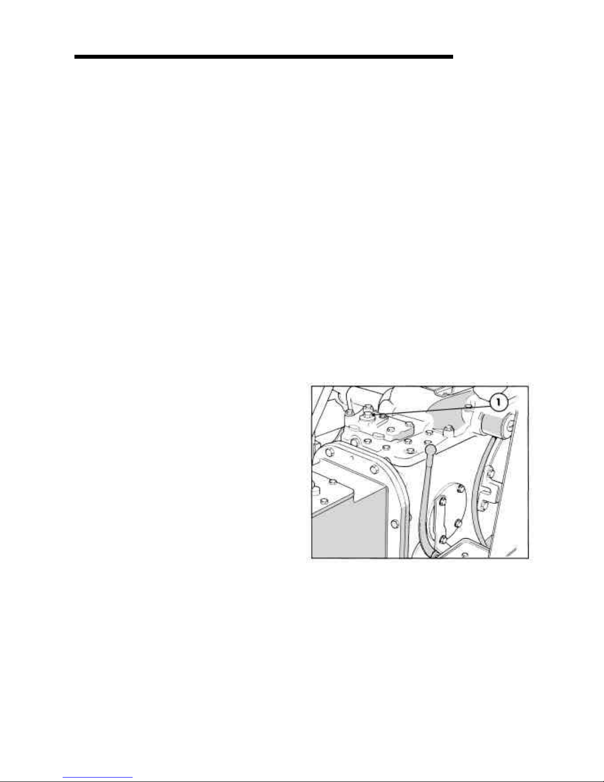
AUXILIARY SERVICES
Accessory Cover (Where fitted)
The live tapping on top of the accessory cover (where
fitted), Figure 14, is connected directly into the tractor
hydraulic circuit. A remote cylinder connected to the
live tapping may be extended or retracted, in conjunction
with the three-point linkage, by moving the Draft Control
Lever.
SECTION A
11
Operating Remote Cylinders with the A.S.C.
Valve (where fitted)
The optional Auxiliary Services Control (A.S.C.) Valve
is installed in place of the accessory cover or remote
control valves and may be supplied with pipe work
leading to a convenient coupling at the rear of the tractor.
Alternatively, remote cylinders may be connected
directly into the tapping on top of the A.S.C. valve. See
Figure 15.
14. Accessory Cover
1. Live tapping
 Loading...