

Page 1
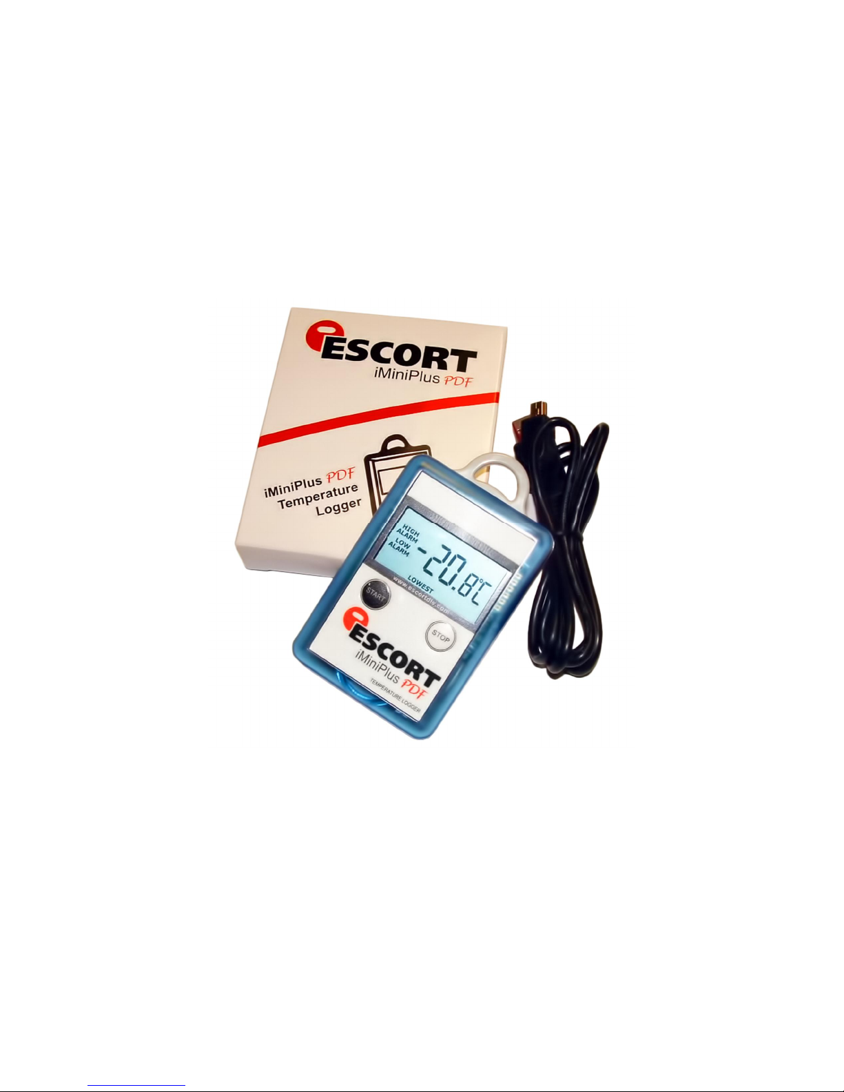
iMiniPlus PDF
User Guide
Version 2.0
Page 2

Table of contents
1
Scope of this document ................................................................................... 3
2
Why PDF? .................................................................................................. 3
3
Logger profile ............................................................................................. 3
4
What you need to get started ............................................................................ 4
5
FDA 21 CFR Part 11 compliance .......................................................................... 5
6
How iMiniPlus PDF Logger works ........................................................................ 5
7
PDF report contents ...................................................................................... 5
8
Connecting logger to PC ................................................................................ 12
9
Programming logger with Console Pro ................................................................ 13
9.1 Customizing PDF report and changing details .................................................... 14
9.2 Programming password ............................................................................ 15
9.3 Configure Sensors and Alarm Settings ............................................................ 16
9.3.1 Specification and Alarm .......................................................................... 17
9.3.2 LCD Display ....................................................................................... 18
9.4 Checking the time clock ............................................................................ 19
9.5 Setting the Start, Stop and logging duration ..................................................... 19
9.5.1
9.5.2
9.5.3
9.5.4
9.5.5
9.5.6
10 Viewing logger data with PDF Reader Software ...................................................... 23
11 Downloading logger readings via Console Pro ....................................................... 23
11.1 Download wizard .................................................................................... 23
12 Creating LCF file from LRF file ......................................................................... 25
13 Does Console Pro work with PDF file? ................................................................. 26
14 Device specifications .................................................................................... 27
15 Contact details .......................................................................................... 28
Duration of trip, at least ..................................................................... 19
Interval between each reading ............................................................. 19
Start new log trip ............................................................................ 21
Finish log trip ................................................................................ 21
Continuous logging ......................................................................... 21
Enable stop button in this logger(s) ........................................................ 22
Page 3
iMiniPlus PDF Logger User Guide v2.0
function
STOPPED – Recording stopped
Low battery icon
Temperature: Latest, highest,
Hold for 3 seconds
Front view
1 Scope of this document
This document only describes new added functionality of USB and PDF to iMiniPlus logger. With the exception of
USB connection and PDF report this logger is essentially iMiniPlus temperature logger. Please refer to iMiniPlus
Logger User guide for all other important information for this logger.
2 Why PDF?
This logger has been developed to eliminate the need of installing proprietary software on PC to view logger data.
The main application for this was logger shipments to remote areas or places where installation of new software
for just occasional downloading data from logger was not justifiable. Portable Document Format developed by
Adobe ® Systems was chosen since almost all PCs have at least one version of Adobe ® Reader installed. The PDF
file generated by the logger is not encrypted and only intended to provide the user with a simple and convenient
method of examining logger data to make a decision on accepting or rejecting the shipment.
3 Logger profile
The iMiniPlus PDF Logger is available in two models. Both have the same temperature range of sensor;
D-range (-40°C to +70°C).
One model has the thermistor sensor mounted inside the logger (Product code MU-IN-D-8-L)
The other model comes with the same sensor as above but encapsulated inside a stainless steel tip on a 1meter
PVC cable. This sensor assembly is permanently connected to the body of the iMiniPlus (Product code MU-OE-D8-L)
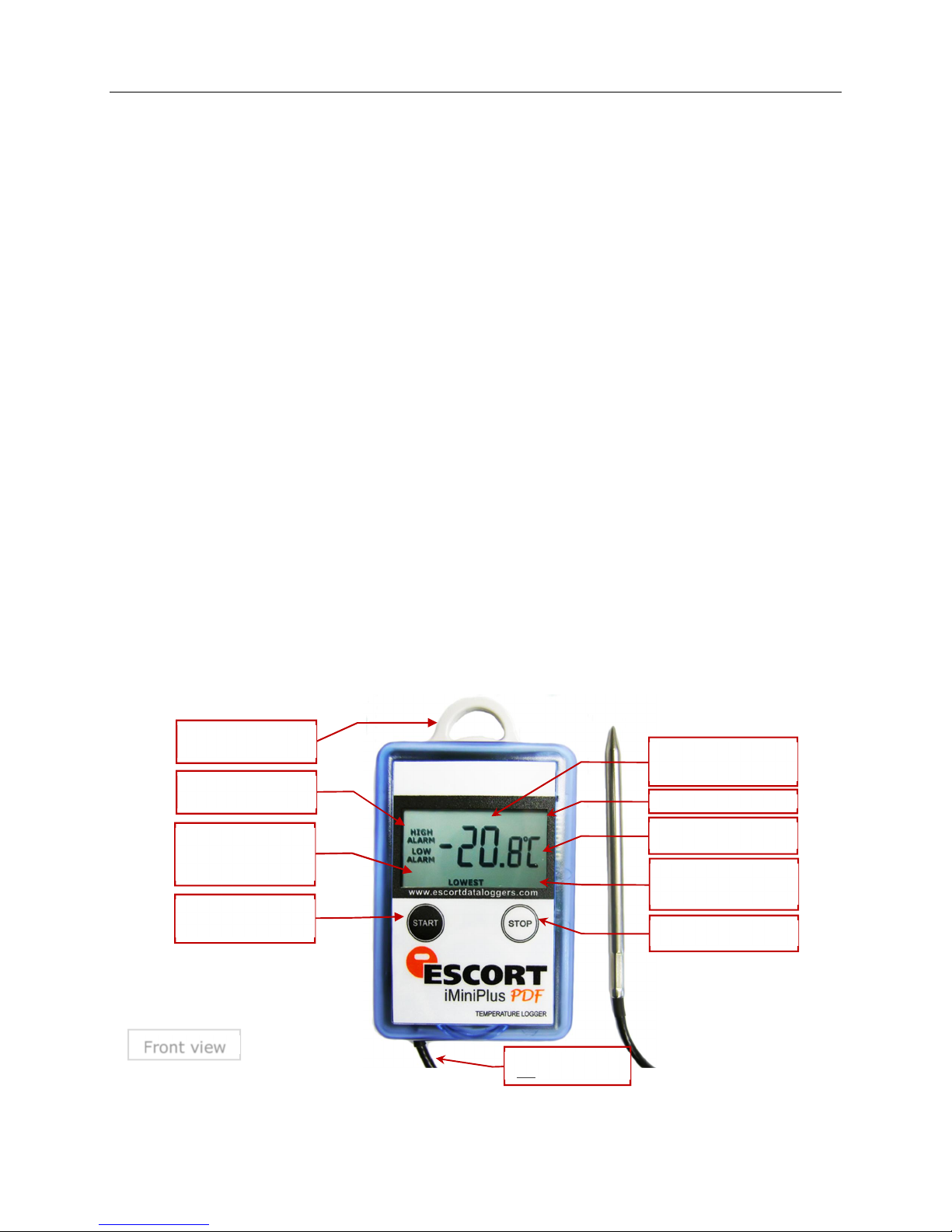
The iMiniPlus has a fully functional LCD display and push buttons. A summary of these features and functions is
described below.
Attachment Lug
For fixing to item or wall
High Alarm / Low Alarm
Alarm has been triggered
Latest - displays current
reading
Marked - Reading has been
bookmarked
Start button
Start, Mark reading and scroll
- 3 -
External sensor
Only MU-OE-D-16-L model
READY - Ready to start
IN DELAY - Started with delay
lowest or average
HIGHEST, LOWEST, AVERAGE
Display high, low and average
recording
Stop button
Page 4
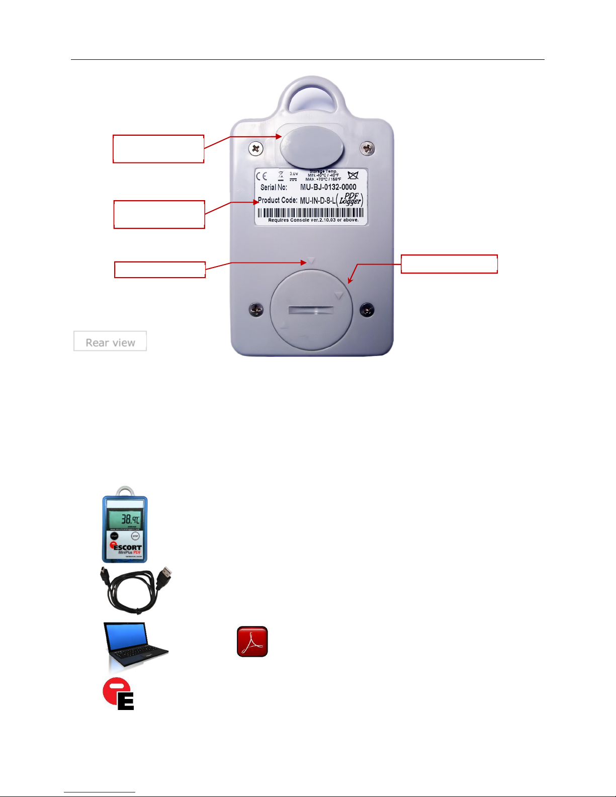
USB connector with water
proof cover
Identification sticker with bar
Alignment marks
Battery cover
Rear view
code
iMiniPlus PDF Logger User Guide v2.0
The iMiniPlus PDF Logger comes with water-proof covers for the USB connection and the battery.
Make sure that when logger is in use these covers are in place. This is important in wet or dusty environments. If
covers are lost please contact your distributor for a replacement.
When replacing the battery align one triangular mark on the battery cover against similar shaped mark on the
logger base to avoid damaging plastic lock feature of the battery cover part.
4 What you need to get started
iMiniPlus PDF Logger
Mini B to A USB cable
PC with PDF Reader software
+
installed
Console Pro Software
installed
- 4 -
Page 5

iMiniPlus PDF Logger User Guide v2.0
5 FDA 21 CFR Part 11 compliance
The PDF report should not be used to provide traceable and auditable data record. The PDF report can be changed
by the user. This is contrary to the FDA 21 CFR Part 11 requirements to data security. In order to produce secure and
traceable record, users have to open LRF with Console Pro and create an LCF file. There is no need to physically
connect logger to PC and download again with Console Pro if logger finished trip. You can just mail LRF and open
it with Console Pro.
6 How iMiniPlus PDF Logger works
iMiniPlus PDF Logger needs to be programmed by Console Pro for logging trip before use.
There is no need to install USB drivers on PC. iMiniPlus PDF Logger is configured as generic USB Mass Storage
Device. All operating systems should install this device automatically using default USB drivers.
iMiniPlus PDF does not require any proprietary software installation to download data from logger after logging
trip is finished.
iMiniPlus normally generates 3 files once connected to USB.
PDF report. This file is used to view logger data. This file is not present if the logger has been configured not
to produce it.
CONTROL.BIN file is used for communication purposes with software
. LRF file is used by Console Pro to create secure. LCF file for traceable data records.
iMiniPlus PDF Logger does not consume battery power when connected to USB and cannot measure or recognize
change in Battery status.
iMiniPlus PDF Logger checks battery status every 15 minutes when not connected to USB and updates Battery
Low icon on LCD.
Console Pro checks battery status of the logger when programming the logger for new trip.
Please note that battery low detect circuit is only accurate when electronics and battery of the is at room
temperatures from 15 °C to 25 °C or from 59 °F to 77 °F. If logger is used in cold environment it may report battery
low prematurely on LCD display. In this case remove logger from cold and check again battery status after 15
minutes or when the temperature of electronics has risen to room temperature range.
7 PDF report contents
You can disable PDF report generation by programming logger with Console Pro software. You can also enable or
disable certain parts of the report as described by the document named “iMiniPlus PDF Logger User guide - working
with Console Pro”.
Accuracy of statistical values displayed in PDF report in Fahrenheit temperature scale is± 0.1 °F.
Accuracy for time out specifications values is ± 1 second.
If first or last reading exceeds specification only half of the log interval is added to the time out of specifications.
- 5 -
Page 6
Header:
iMiniPlus PDF Logger User Guide v2.0
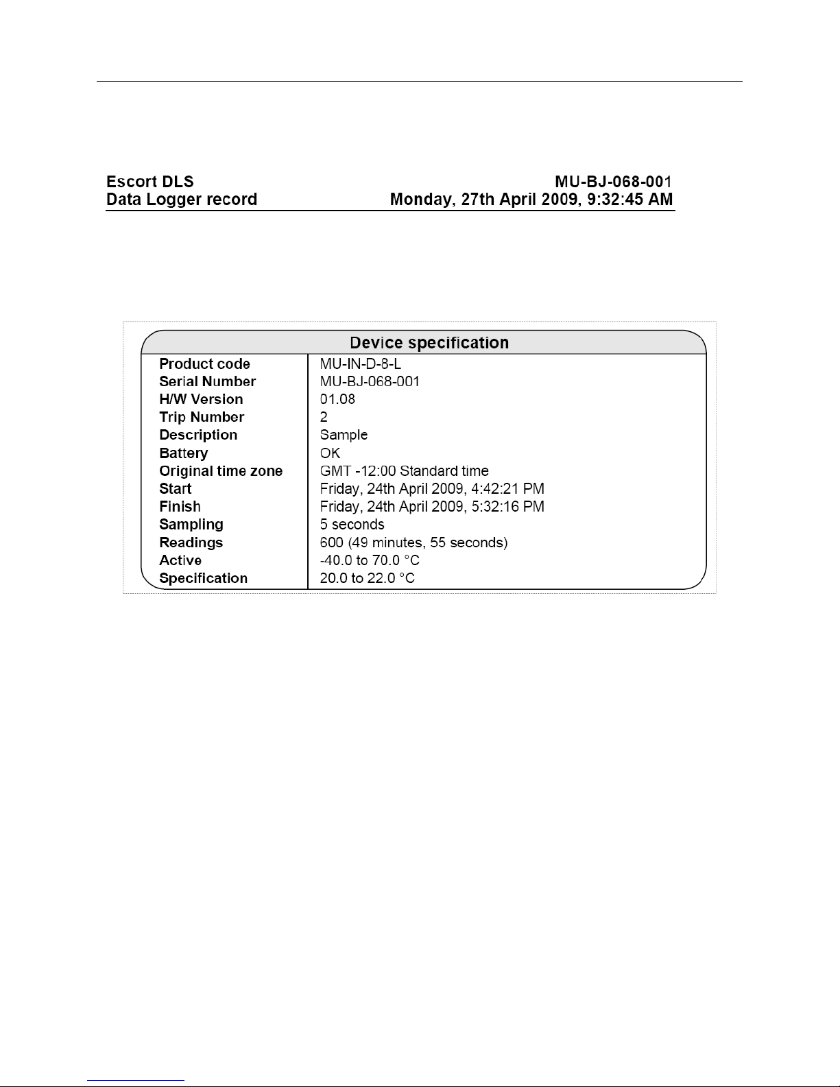
Each header displays logger serial number and date / time information from logger without time zone and daylight
saving settings.
Device specification
Device specification part includes:
Product Code
Serial Number of the logger
Hardware version – this is actually firmware version
Description string programmed to the logger by Console Pro
Battery status last measured by the logger before it has been connected to PC
Time Zone and daylight savings programmed to the logger
Date / Time when logging trip started
Date / Time when logging trip finished
Current number of readings and total duration of the trip
Logger temperature range
Alarm limits programmed to the logger
- 6 -
Page 7
Statistics
iMiniPlus PDF Logger User Guide v2.0
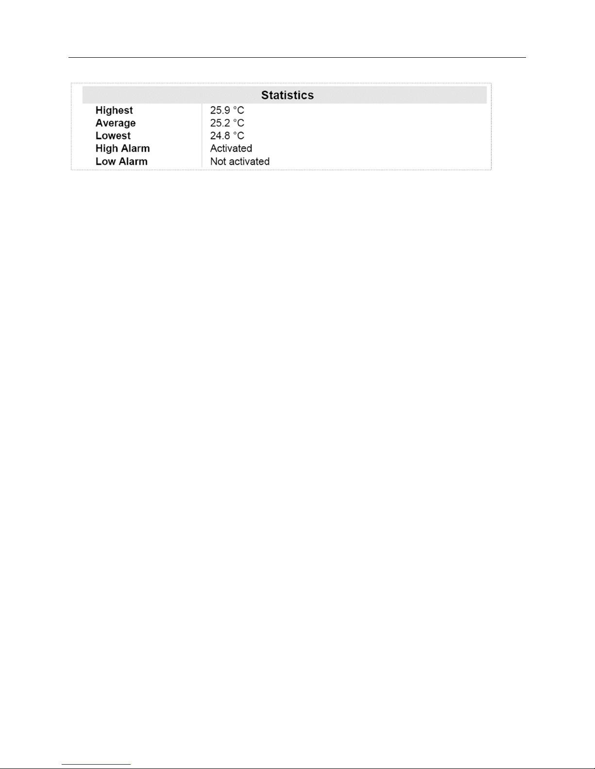
Statistics part includes:
Highest temperature reading for the current trip
Average temperature reading for the current trip.
Please note: if the logger is configured for continuous logging, logger memory is getting overwritten and logger
only holds the last 8048 readings. Logger computes average that includes all readings even the ones already
overwritten. Console Pro computes average based on readings retrieved from logger memory and result may
be different.
Lowest temperature reading for the current trip
High Alarm status
Low Alarm status
Both High and Low Alarm can have the following status:
o Disabled – Alarm was not enabled when logger was programmed
o Activated – Alarm has been programmed and triggered
o Not activated – Alarm was programmed but has not been triggered
Record
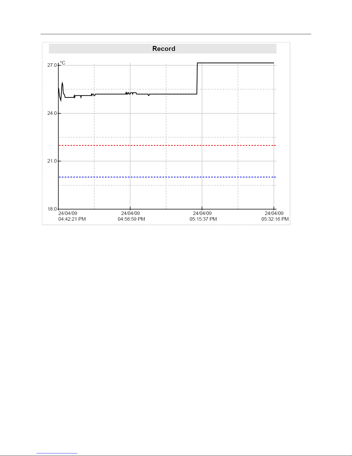
The picture below is an example of a graph section in a report of the logging trip with High Alarm set to 22 °C Low
Alarm set to 20 °C and Catastrophe Alarms disabled. Note that only two coloured dashed lines are displayed for
primary alarm limits.
- 7 -
Page 8
iMiniPlus PDF Logger User Guide v2.0
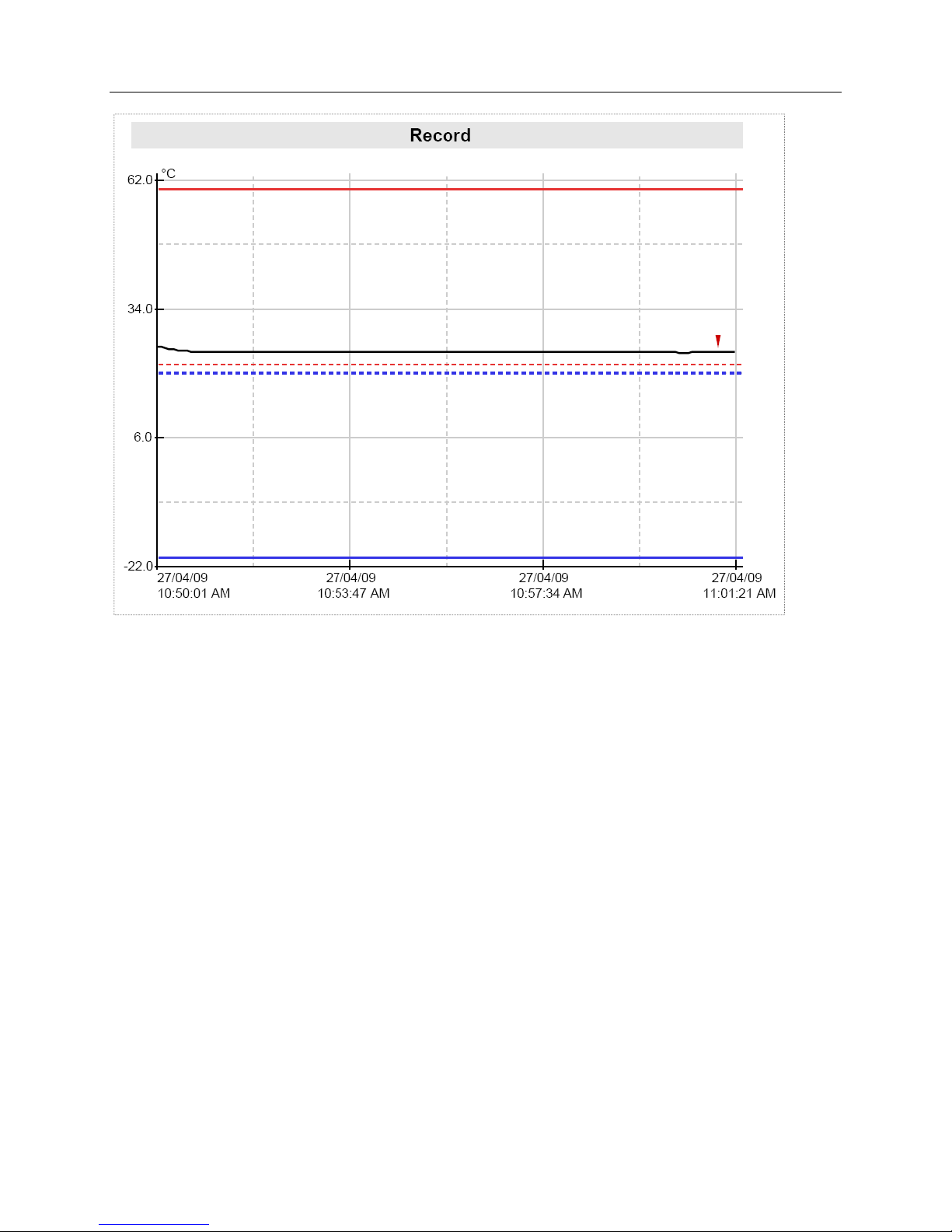
The picture below is a graph report of the logging trip with High Alarm set to 22 °C Low Alarm set to 20 °C, High
Catastrophe Alarm set to +60 °C Low Catastrophe Alarm set to -20 °C. Note that the graph contains coloured
dashed lines for primary alarm limits and solid coloured lines for catastrophe alarm limits. Note that the numerical
values of the alarm limits are not shown on a graph. “Specification” field of “Device Specification” section
contains information of High and Low Alarm settings. Numerical information about Catastrophe Alarm limits is
not available in PDF report.
- 8 -
Page 9
iMiniPlus PDF Logger User Guide v2.0
This part of the report is a graph of readings for the current trip.
This part of the report can be disabled when programming.
You can change date display format to display month first by programming logger.
Date and Time is displayed along the X axis.
Temperature values are displayed up the Y axis.
If Alarms are disabled Alarm limits are not displayed on the graph
- 9 -
Page 10
iMiniPlus PDF Logger User Guide v2.0
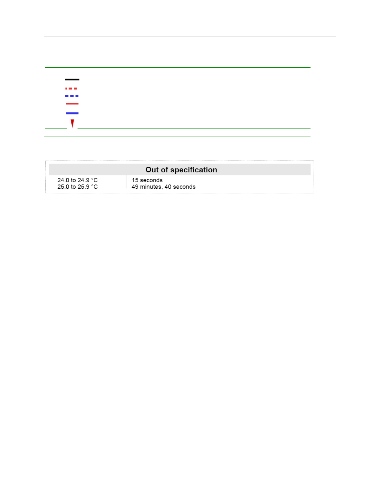
Graph Legend
Symbol Meaning
Logger readings
High Alarm Limit
Low Alarm Limit
High Catastrophe Alarm Limit
Low Catastrophe Alarm Limit
Marked reading
Out of specifications
Out of specification is a report of how long the logger spent outside of alarm limits
This part of the report can be disabled when programming
Each line in this report can be read as:” Logger has spent 49 minutes and 40 seconds between 25 °C and 25.9
°C”, in this case the value of 1 degree per report line is configured by programmable parameter named
“Increment”.
Note: if Fahrenheit temperature unit scale is selected, the accuracy of “Out of specification” report summary
increment limits are ±0.1°F due to the complexity of conversion between Fahrenheit and Celsius. The same report
produced by Console Pro may differ from PDF report produced by the logger in term of temperature by ±0.1°F.
Duration of out of specification and the list of readings will read the same.
- 10 -
Page 11
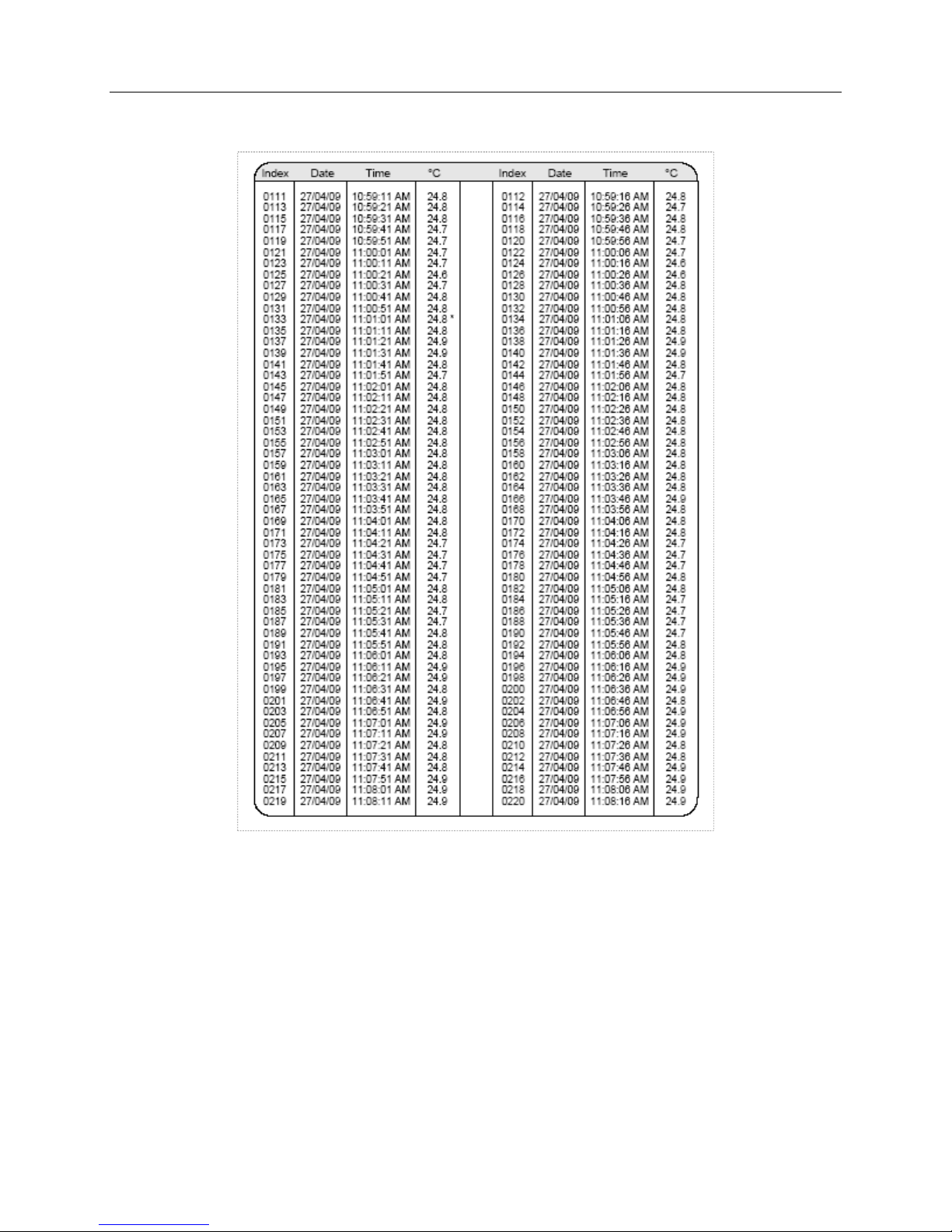
List of readings
iMiniPlus PDF Logger User Guide v2.0
This part of the report always has two columns.
This part of the report can be disabled when programming
You can change date display format to display month first by programming logger
Marked readings are displayed with asterisk sign.
If logger has full 8048 readings, the list of readings will be 73 pages long.
- 11 -
Page 12
iMiniPlus PDF Logger User Guide v2.0
8 Connecting logger to PC
You need to install Console Pro (please download from
www.cryopak.com
) in order to program iMiniPlus PDF.
Please refer to iMiniPlus Logger User guide for information on Console Pro installation. This software runs in
Microsoft Windows only.
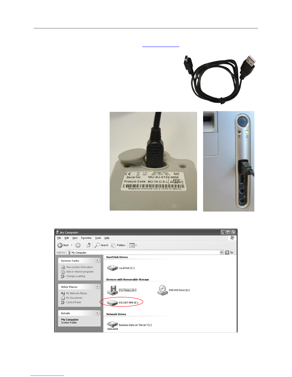
Second step is unpacking the logger. You will find a USB cable in the box
with the logger.
The cable has two different ends. The smaller one is type Mini B and the
bigger one is type A. Connect USB cable with Mini B (smaller) connector
to the logger and A size to PC or laptop computer as illustrated below.
Simply connect the logger to your
PC and wait until the Operating
System installs device drivers.
Please allow Windows sufficient
time to install the device. Please do
not connect multiple loggers at the
same time since it may cause
unexpected behavior.
Once the device is installed, you can
see the logger as External
Removable Drive named MPP in
“My Computer” and in Console Pro.
- 12 -
Page 13
iMiniPlus PDF Logger User Guide v2.0
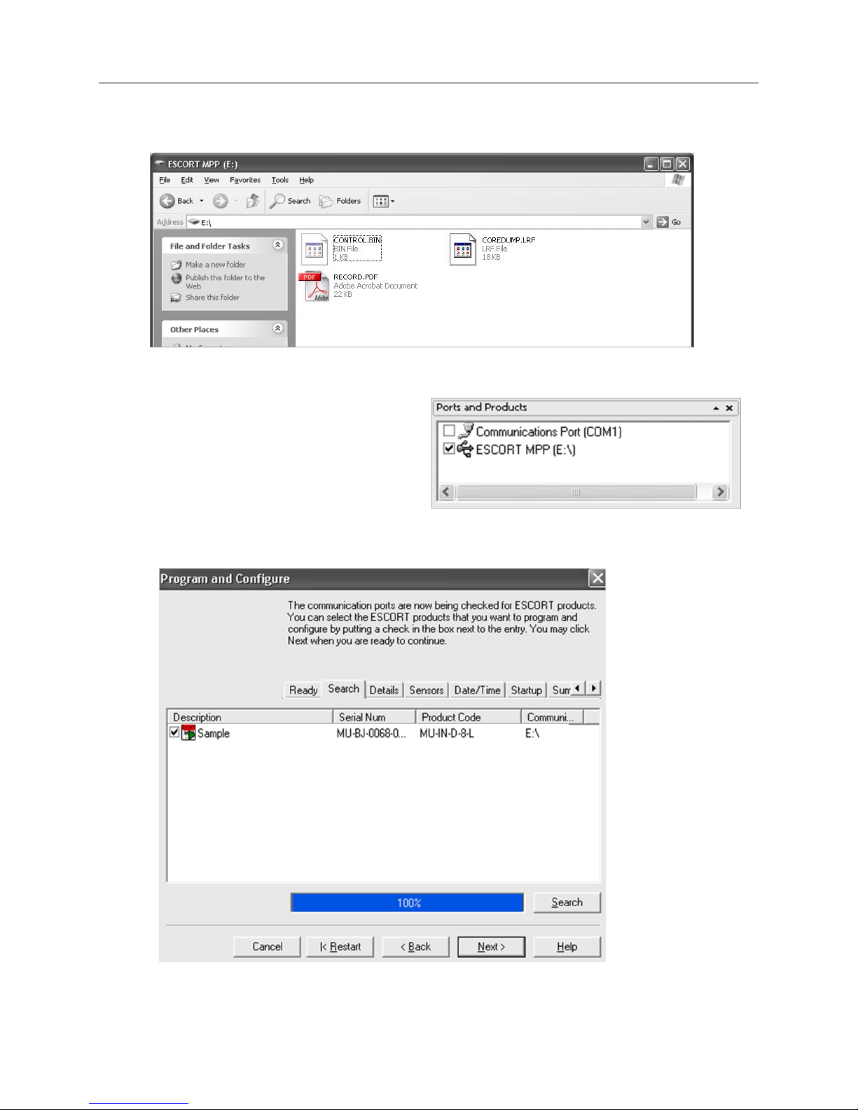
Inside this drive you can see the following:
9 Programming logger with Console Pro
You have to use Console Pro Professional version
2.12.07 or later to program the logger.
Check this check box and click on “Program and
Configure” button on the toolbar.
Program Wizard should start. Then click “Next”. Logger should be recognized and displayed.
- 13 -
Page 14
iMiniPlus PDF Logger User Guide v2.0
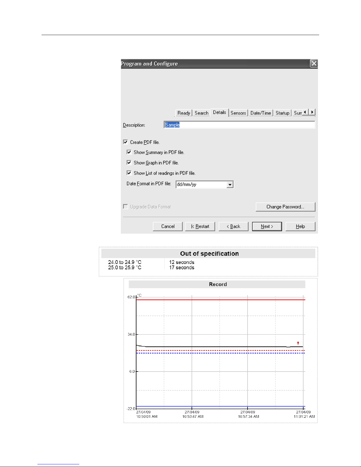
9.1 Customizing PDF report and changing details
Click on “Next” button. You
can see editable
“Description” field and
options for customizing PDF
report:
You can customise PDF
report generated by the
logger, by checking or un
checking these boxes.
If you check all boxes, the
logger will generate a full
report that can be several
pages long depending on the
number of readings.
If you uncheck “Create PDF
file” checkbox, the logger
will not generate PDF report
at all. You may need this
option to prevent unwanted,
unauthorized or incidental
access to the data from the
logger without Software.
If you uncheck
“Show summary in
PDF file” the logger
will not generate the
section of the report
that summarizes alarm
violations of the logging trip as
shown below:
If you uncheck “Show Graph in
PDF” the logger will not
generate the graph as shown
below:
- 14 -
Page 15
iMiniPlus PDF Logger User Guide v2.0
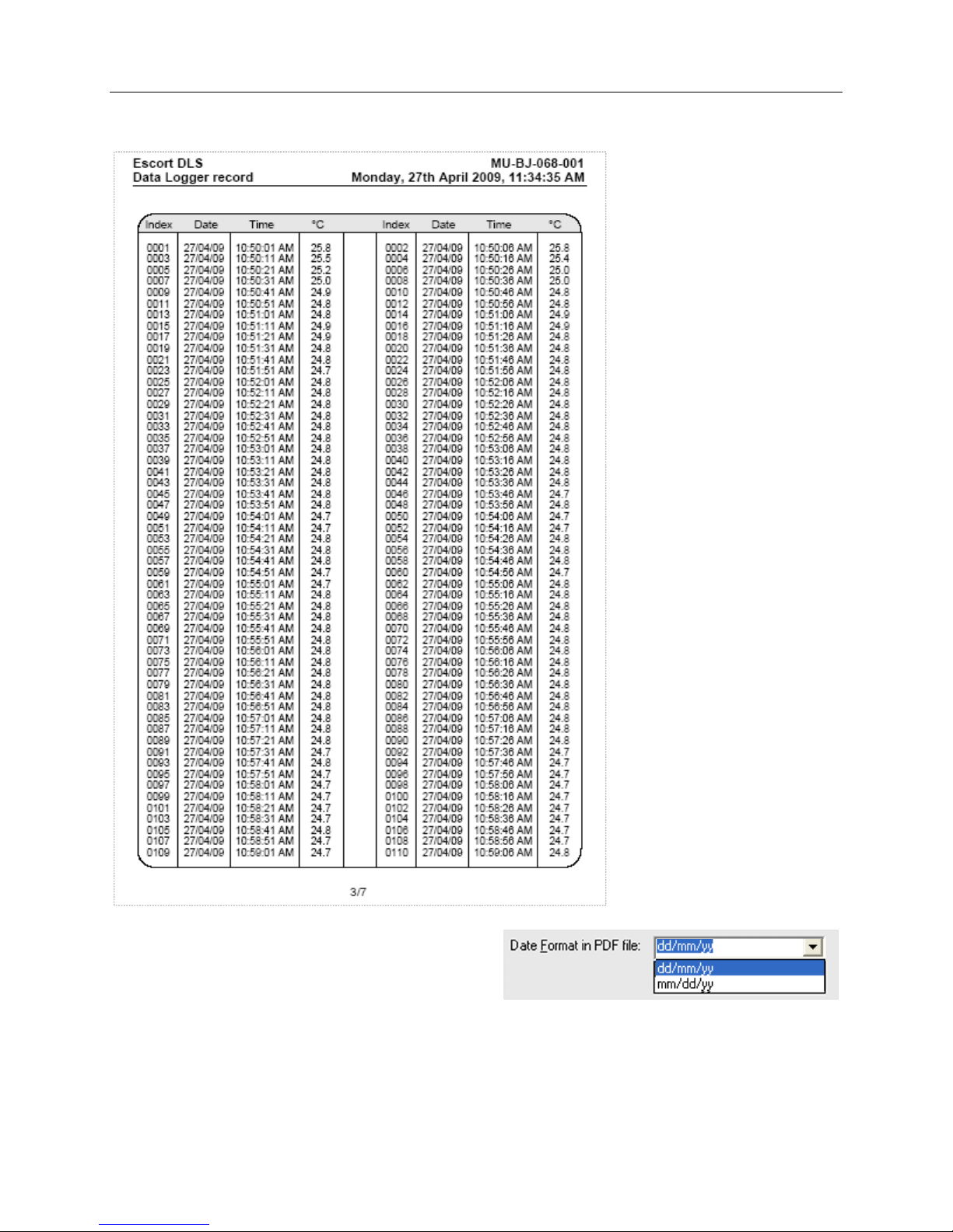
If you uncheck “Show list of readings in PDF file”, the logger will not generate the list of readings report as shown
below:
You can configure the logger to display date in month /
day / year or day / month / year format by choosing one
option from drop down box on this tab as shown below:
9.2 Programming password
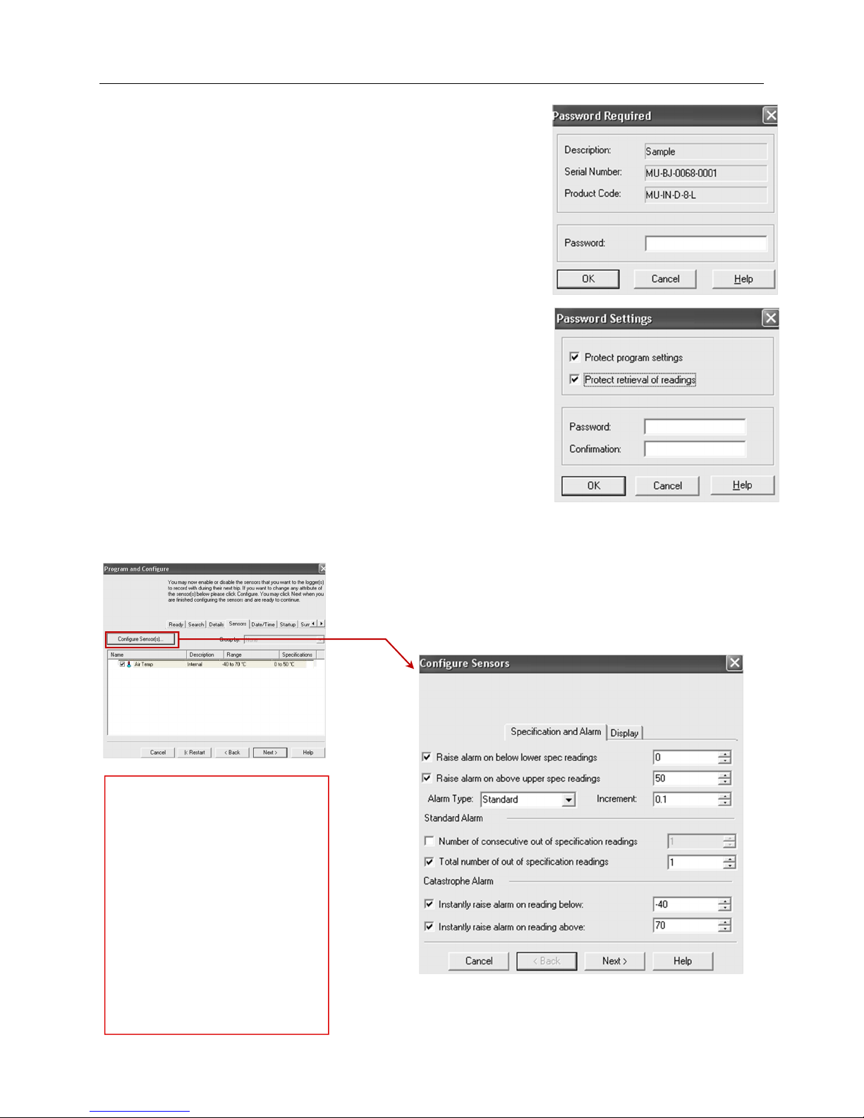
The iMiniPlus PDF Logger supports a password option that, when enabled, results in users being required to provide
the correct password to gain further access to the iMiniPlus PDF Logger. When the password option is enabled, a
window similar to the following picture will be displayed allowing the user to enter the correct password.
- 15 -
Page 16
iMiniPlus PDF Logger User Guide v2.0
The Program and Configure process will only continue successfully if the
correct password is supplied by the user. Passwords are digits only, up to 4
characters.
You can enter a password to safeguard your logger from unauthorized
tampering. Make sure that you keep a note of your password and logger
serial number in a safe place. If you lose or forget the password, the logger
will have to be returned to your nearest distributor or Cryopak to restore
default password.
Change Password – if you have password protected the iMiniPlus PDF
Logger or want to add a password for the first time you can do this here.
Protect program settings - Tick this option if you want to protect your
programming settings for the current logger.
Protect retrieval of readings- Tick this option to disallow viewing of data
from the current logger without a password.
After complete the password section, click OK
Select the Next button or Sensors tab.
9.3 Configure Sensors and Alarm Settings
Sensors Tab – this displays the
sensor information some of which
can be changed by using Configure
Sensor(s) and others that remain
fixed i.e. range -40C to 70C. The
description “Internal” refers to the
type of sensor as opposed to
“External” which will display on the
external sensor model.
Configure Sensor(s)… – click on this
button to set up the alarm and LCD
display parameters.
- 16 -
Page 17
iMiniPlus PDF Logger User Guide v2.0
9.3.1 Specification and Alarm
Raise alarm on below lower spec readings – tick this box if you want to activate the low alarm and select the value
in the box immediately to the right. Note if the lower spec value is 0C, then the alarm is triggered at -0.1C, not
0.0C as this value is considered within specification.
Raise alarm on above upper spec readings – tick this box if you want to activate the high alarm and select the
value in the box immediately to the right. Note if the upper spec value is 50C, then the alarm is triggered at 50.1C,
not 50.0C as this value is considered within specification.
Increment - the grouping size used for listing out-of-specification readings.
Alarm Type
This feature allows the user to specify the conditions that will trigger an alarm.
Standard Alarm
Number of consecutive out of specification readings – the alarm is triggered if the readings are consecutively over
or under the specified threshold. For instance, if the upper spec is 50C and the value for the number of consecutive
out-of-spec readings is 3 and the logging interval is 10minutes, the readings will need to be in excess of 50°C for 30
minutes before the alarm is triggered. If the readings fluctuate outside upper and lower threshold temperatures,
the same rule applies (providing the appropriate “raise alarm” box is ticked). Once the reading(s) return inside alarm
limits, the consecutive alarm is reset.
Total number of out of specification readings (cumulative) – the alarm is triggered if the total number of out of
spec readings equals or exceeds the entered value. In this case the alarm is NOT reset if readings return to within
the specified parameters.
Do not set the Total number of out-of-spec readings value to be less than the Consecutive out-of-spec readings as this
will mean that the Consecutive out-of-spec readings alarm will never be triggered.
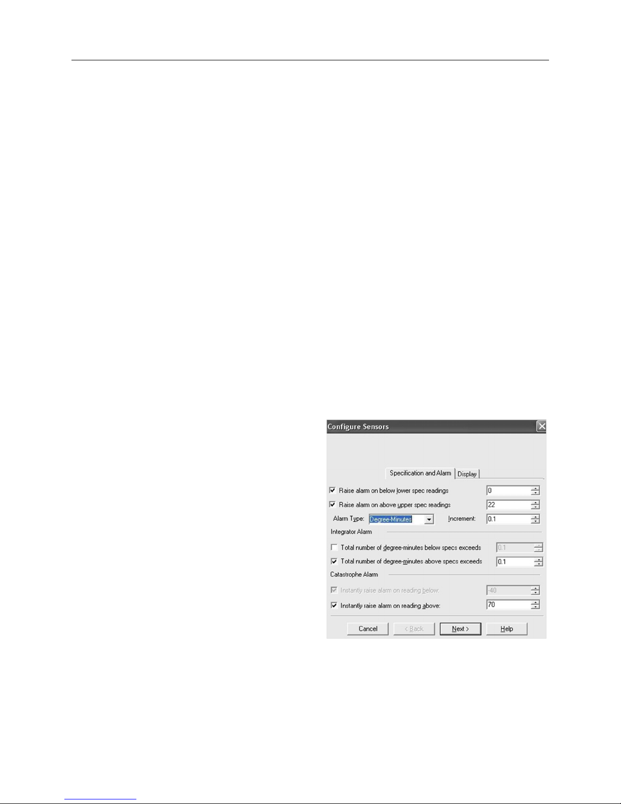
Degree-Minutes Alarm (Integrator Alarm)
The Degree-Minutes Alarm is a special feature that
“integrates” temperature and time parameters into one
value.
Total number of degree-minutes below specs exceeds the alarm is triggered when the total number of
temperature degrees’ times the minute’s duration below
the low alarm spec is greater than the value entered.
Total number of degree-minutes above specs exceeds the alarm is triggered when the total number of
temperature degrees’ times the minute’s duration above
the upper alarm spec is greater than the value entered.
Catastrophe Alarm
This alarm is always additional to the Standard and
Degree-Minute alarms and there is no delay. Do not set
Catastrophe Alarm inside normal alarm limits because other alarms will never be triggered.
Instantly raise alarm on readings below - tick this box if you want to immediately trigger the low alarm and select
the value in the box immediately to the right. Note if the lower spec value is 0 °C, then the alarm is triggered at -0.1
°C, not 0.0 C as this value is considered within specification.
- 17 -
Page 18
iMiniPlus PDF Logger User Guide v2.0
Instantly raise alarm on readings above - tick this box if you want to immediately trigger the high alarm and select
the value in the box immediately to the right. Note if the upper spec value is 50 °C, then the alarm is triggered at
50.1 °C, not 50.0 °C as this value is considered within specification.
The table below demonstrates arbitrary data from an iMiniPlus PDF Logger and how different alarm sources
will be triggered. This is complicated scenario for alarm settings based on:
Upper spec alarm: +20C
Number of Consecutive out of spec readings: 4
Total number of out of spec readings: 5
Total number of degree-minutes above specs exceeds: 8
Instantly raise alarm on readings above: +23C
Time [min] T [ ºC] Consecutive Total Integrator Catastrophe
0 19 OFF / 0 OFF / 0 OFF/0 OFF
1 20 OFF / 0 OFF / 0 OFF/0 OFF
2 23 OFF / 1 OFF / 1 OFF/3 ALARM ON
3 21 OFF / 2 OFF / 2 OFF/4 ALARM ON
4 19 OFF / 0 OFF / 2 OFF/4 ALARM ON
5 21 OFF / 1 OFF / 3 OFF/5 ALARM ON
6 22 OFF / 2 OFF / 4 OFF/7 ALARM ON
7 24 OFF / 3 OFF /5 ALARM ON /11 ALARM ON
8 22 OFF / 4 ALARM ON /6 ALARM ON /13 ALARM ON
9 21 ALARM ON /5 ALARM ON /7 ALARM ON /14 ALARM ON
10 19 ALARM ON/0 ALARM ON /7 ALARM ON /14 ALARM ON
9.3.2 LCD Display
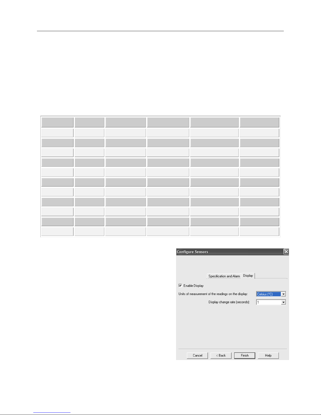
The iMiniPlus PDF Logger LCD can be configured to display
or not display the temperature information.
Enable Display
Tick this box if you want to enable the display to show the
temperature readings and statistics.
If the box is un-ticked, all other features will be grayed out.
The iMiniPlus LCD will show “d-off” instead of a
temperature value. Additionally, you will not be able to
scroll through the highest lowest, average and out of spec
readings. The word “LATEST” will flash and if any alarm
had been triggered, “HIGH ALARM” or “LOW ALARM”
will be displayed.
The bookmarking function can still be used when the
display is disabled.
When the iMiniPlus is stopped using the Stop button or it
stops because it has reached the end of a logging trip, the
words “d-off” will disappear and the word “STOPPED” will appear.
- 18 -
Page 19
iMiniPlus PDF Logger User Guide v2.0
and time is correct.
recording and stop conditions.
Display Units of measurement
You can select the LCD to display the temperature in Celsius or Fahrenheit.
Display change rate
You can select a frequency or 1, 2, 3 or 4 seconds that the LCD scrolls between the Highest, Lowest, Average and
out-of-spec information. Note that the “LATEST” reading will only change at a frequency equal to the logging
interval. So if the iMiniPlus is programmed to log every 1 minute that will be the rate at which the “LATEST”
reading changes.
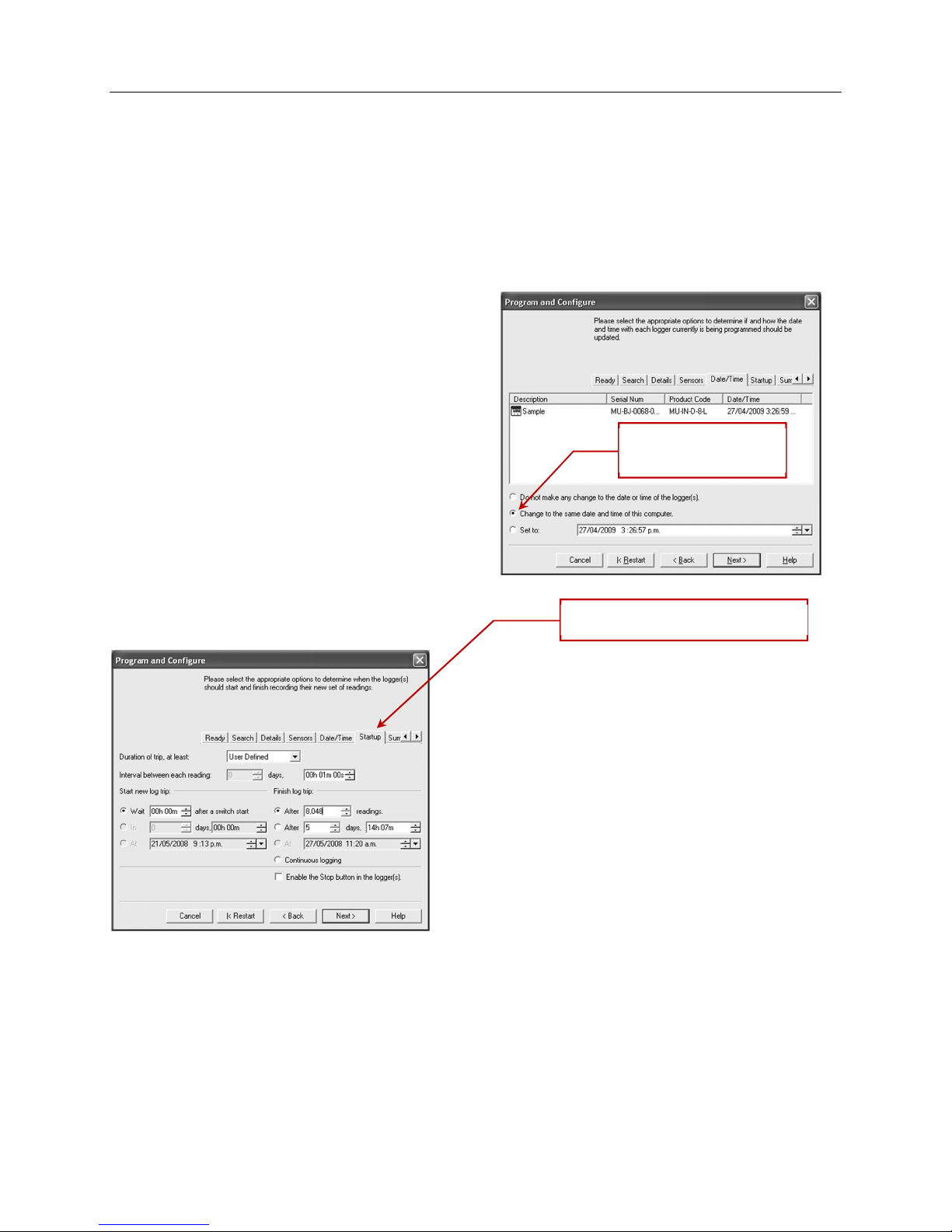
9.4 Checking the time clock
There may be times when the time clock on the iMiniPlus
PDF Logger may alter. This is the case when the battery is
removed and not replaced within 30seconds.
If you have removed batteries from the iMiniPlus PDF
Logger for any length of time, make sure you either select:
Change to the date and time on this computer
(default)
Set to
The software will always default to the “Change to the
date and time on this computer.” option.
9.5 Setting the Start, Stop and logging duration
9.5.1 Duration of trip, at least
If you are using the iMiniPlus PDF Logger to record the
temperature of a trip (shipment) for instance, you have the
option of setting up the parameters yourself or let the Console
Pro software calculate these automatically for you.
The software takes the total memory available (8048 readings)
and calculates the maximum interval between each reading
and the finish log trip time and date based on the trip duration
you select. You can select 1 day to 60day trip duration this way.
You will notice that each time you select trip duration, the
logging interval will change.
Date/Time Tab Check that the date
Startup Tab - Configure the start,
9.5.2 Interval between each reading
This is sometimes called the logging interval or logging rate and is described as the period of time between each
logged reading. If the interval is a low number, then the iMiniPlus memory will be filled quickly compared to a high
number. If you want to record acute changes in temperature over short periods of time, it is best to select a low
number or faster logging interval. If you want a logger to record readings over a long period of time, then you will
be best advised to use a lower logging interval or high number.
The fastest logging interval the iMiniPlus PDF Logger can log at is every 5 seconds.
The slowest logging interval the iMiniPlus PDF Logger can log is every 18 hours.
- 19 -
Page 20

iMiniPlus PDF Logger User Guide v2.0
- 20 -
Page 21

iMiniPlus PDF Logger User Guide v2.0
9.5.3 Start new log trip
The only way to start an iMiniPlus PDF Logger is by using the START button. With other products it is possible to
have a timed or date start as well as a switch start.
You can also program a delay into the starting process of up to 4 hours 15 minutes. This will show immediately
after the Start button is pressed within the iMiniPlus LCD with the words “IN DELAY”.
9.5.4 Finish log trip
There are several ways to cease a logging trip or period.
You can program the iMiniPlus PDF Logger to log until all the memory is used up (8048 readings) or you may wish
to log only 100 readings for instance.
Alternatively, you can select a certain number of days at which the iMiniPlus will stop logging. For instance, you
may only want to record the temperature for a discrete period like a few days, after which you are not interested in
any further data recording.
At the prescribed time the iMiniPlus PDF Logger will stop logging and “STOPPED” will be displayed on the LCD.
You can also enable the “STOP” button on the logger. This is disabled by default, because in most applications it is
better to take too many readings than too few.
Downloading the logger (reading the stored results into the computer) does not interfere with a running trip.
However, if you Program the logger with new trip settings while it is still running, the previous trip data are lost. In
other words, be sure to download and save the previous trip before setting up a new one. In this case “READY” is
displayed on the LCD.
9.5.5 Continuous logging
If you are intending to place the iMiniPlus in an environment that you want to record temperatures 24/7 (for
example, laboratory refrigerator), you can select the iMiniPlus PDF Logger to log continuously. This means that the
iMiniPlus PDF Logger will log until the memory it filled up at which time it will start overwriting the first logged data
with the latest.
Users must be careful to routinely download data from the iMiniPlus PDF Logger otherwise data may be lost.
Careful selection of the logging interval is required in this case.
It is possible to download at any time while the iMiniPlus PDF Logger is logging, without changing the program
settings.
- 21 -
Page 22
iMiniPlus PDF Logger User Guide v2.0
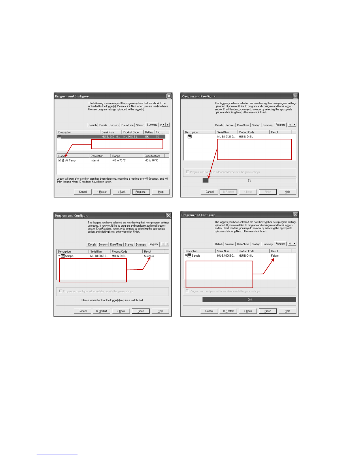
Check program settings
PDF Logger
9.5.6 Enable stop button in this logger(s)
The iMiniPlus PDF Logger Stop button can be activated through programming by simply ticking the appropriate
box.
Select Next button or Summary tab.
Program conditions are
being uploaded to iMiniPlus
Select Program button or Program tab.
The iMiniPlus PDF Logger
has been programmed
successfully
Program conditions have
not been successfully
uploaded into the
iMiniPlus.
Click “Finish” button.
If the upload has failed either select the Cancel button to close the software and start again or select the Restart
button to start the sequence again. If the iMiniPlus PDF Logger still fails to upload contact your local distributor or
Data Logging Systems.
- 22 -
Page 23
iMiniPlus PDF Logger User Guide v2.0
10 Viewing logger data with PDF Reader Software
You can download data from the logger by connecting the logger to a USB port. Once the logger hardware is
installed and logger can be recognized by Operating System as Mass Storage Device you can open RECORD.PDF
file. You can validate logger data by simply looking at PDF report.
Please note that PDF Reader software is not able to save opened PDF file to other location if logger has been
disconnected from PC after PDF report was opened with PDF Reader.
Please note if you can not save PDF Report opened in PDF Reader software using “Save As” menu item you can
always copy file using Windows Explorer and paste it to the desired location.
11 Downloading logger readings via Console Pro
You can download data from the logger by connecting the logger to Console Pro.
Make sure the USB cable is connected to your PC and to the iMiniPlus PDF Logger.
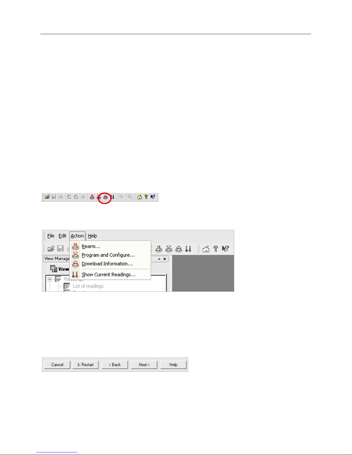
There are two ways to retrieve the data from an iMiniPlus PDF Logger, both of which will achieve the same result.
1. Click the Download Information icon on the toolbar
2. Click the "Download Information..." item located under the Action menu.
The process of retrieving data stored within an iMiniPlus PDF Logger does not erase it from the memory. If the
iMiniPlus is currently recording while you retrieve the information, it will continue to record without interruption.
The Download Information feature initiates the Download Wizard.
11.1 Download wizard
During the progress of the Download Wizard, you will see a series of 5 buttons at the bottom of the wizard box.
The “Cancel” button immediately stops and closes the wizard. To start again you will have to select the Download
icon. The “Restart” button enables you to start the Wizard progress from the beginning without closing the
feature. “Back” enables you to go back one step in the step-by- step progress and “Next” takes you to the next
step. The Next button is preceded by the “Download” button. The Help button will provide description and
instruction about the step you are in. Please note that this feature may make reference to other products from
- 23 -
Page 24
iMiniPlus PDF Logger User Guide v2.0
time to time. Additionally some Help documentation may not be present due to the software version you are
currently using. Consult this iMiniPlus PDF Logger User guide if you are not sure about any description.
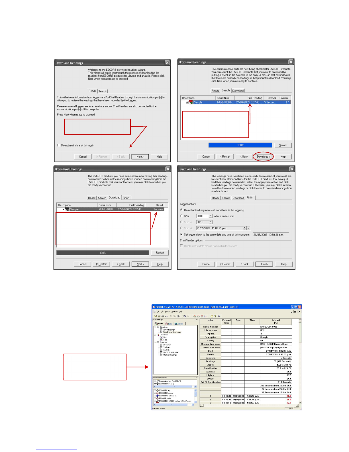
Displays information
Download Wizard Start
page
about the iMiniPlus along
with the date and time
of the first reading.
Indicates that the Download was successful. If
FAILURE appears in the Result and there is a
RED X next to in the Description this may
indicate the iMiniPlus PDF Logger has already
been programmed. If this is not the case, there is
a fault with the iMiniPlus and it will need to be
You have the option of programming new start conditions. This may be help for instance when you are having to
reset a large number of iMiniPlus loggers for a new application. Otherwise leave the Logger option at its default
setting “Do not upload any new start conditions to the logger(s)”
Click on the Finish button.
Readings and
Summary is
displayed.
- 24 -
Page 25
iMiniPlus PDF Logger User Guide v2.0
12 Creating LCF file from LRF file
By its very nature (it was created in order to share information across all
operating systems and computers) the PDF “Portable Document Format” is
not secure. Logger data saved in 's proprietary LCF “Logger Compact Format”
is secure.
This is a new feature that enables you to create a *.LCF file from the .LRF file
that is generated by the logger, without the need to communicate with the
logger. In other words you can email LRF files and Console Pro will create an
LCF file from the LRF file. Then you will be able to add digital signatures to
the LCF file, view data, compare information with the received PDF file and
securely archive the data for auditing purposes.
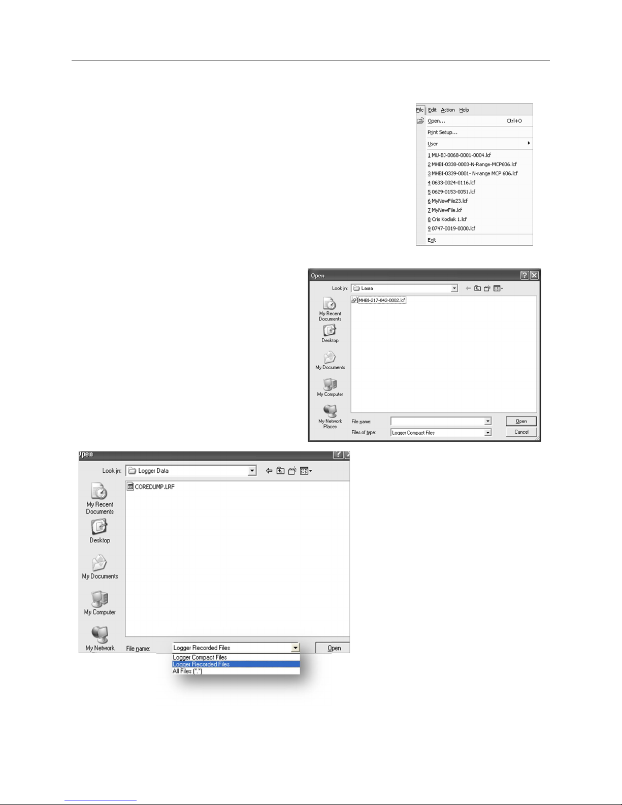
To open the LRF file you need to go to File-> Open menu item or use “Ctrl+O”
shortcut key.
The following window will be displayed:
Expand “Files of Type” drop down box and choose
“Logger Recorded Files” as shown below:
Navigate to the file you want to open and click on
“Open”
Console Pro should display List of readings as
shown below:
- 25 -
Page 26
iMiniPlus PDF Logger User Guide v2.0
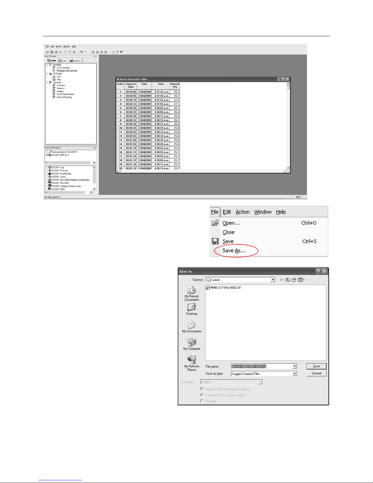
Now you can view logger data in various forms by clicking on
menu items of “Views” window on the left. You can also
validate the received PDF report of the logger with Console Pro.
Now you can save data in LCF (Logger Compact File) format by
clicking on the “File -> Save As” menu item in the main menu:
The following dialog should be displayed:
Please ensure that file name is unique. By default
Console Pro assigns the logger’s serial number and
trip number to the name of the file. Navigate to the
secure location and click on the “Save” button.
13 Does Console Pro work with PDF file?
Console Pro neither opens logger PDF report nor
creates one.
Console Pro only works with LRF and LCF files.
In order to ensure that the PDF file has not been
tampered with you need to visually compare it with
Console Pro view of the LRF file.
- 26 -
Page 27

iMiniPlus PDF Logger User Guide v2.0
14 Device specifications
Parameter Value
Operating Temperature D range: -40 ºC to +70 ºC ( -40 ºF to +158 ºF)
Product Code MU-IN-D-8-L (Internal sensor)
MU-OE-D-8-L (External sensor)
MU-ST-D-8-L (Single Trip Internal sensor)
Sensors 1 x Internal or 1 x External sensor options
Accuracy
Celsius: from -40 ºC to -10 ºC ±0.5ºC
from -10 ºC to +70ºC ±0.3ºC
Fahrenheit: from -40 ºF to +14 ºF ±1ºF
from +14 ºF to +158 ºF ±0.6ºF
Resolution Display resolution of 0.1ºF or 0.1ºC
IP Rating IP65 (with plastic cap over USB connector)
Size 83mm x 57mm x 17 (Case excluding lug)
Weight 70 grams
Temperature response
time
Internal Sensor – T90 of 20 minutes in moving air
External Sensor – T90 of 5 minutes in moving air
Time and date Real time clock accurate to 1minute per month
Sampling frequency 5 seconds – 18hours
Power source User replaceable 3V lithium coin cell
Typical battery life 1 – 2 years’ operating life from a user-replaceable battery (depending on
usage)
Software
No software is needed to view log trip report
Console Pro version 2.10.03 or later for programming and secure
download
Available free at www.dls.com
Warranty 24 months (excluding batteries)
Case material Polycarbonate/ABS
Data Security
Password protected (programmable using Console Pro software)
encrypted binary file is generated along with PDF
Liquid crystal display Operating temperature -20C to +70C (-4F to +158F)
1st button press - High, low, average readings
2nd button press - Time spent under/ over specifications
Buttons “START” and “STOP”
Communications USB
DISCLAIMER: Data Logging Systems Limited reserves the right to change the specifications without notice
- 27 -
Page 28
iMiniPlus PDF Logger User Guide v2.0
15 Contact details
If you require further information regarding CRYOPAK Verification Technologies, Inc. products
please contact us at:
USA
Mailing Address: PO Box 309, Buchanan, VA 24066
Office: 120 Parkway Drive, Buchanan, VA 24066
Phone: +1-540-254-1433
+1-732-346-9200 Ext. 150
Fax: +1-540-254-2433
Email: [email protected]
CANADA
FRANCE
You can find additional information regarding all of our products on our website:
Address: TCP Cryopak France
1 Rue Berthelot
Z.I. La Maine
76150 Maromme
Phone: +33 2 32 82 59 65
Email: [email protected]
www.cryopak.com
http://www.cryopak.com/en/verification-products/
- 28 -
 Loading...