

Page 1
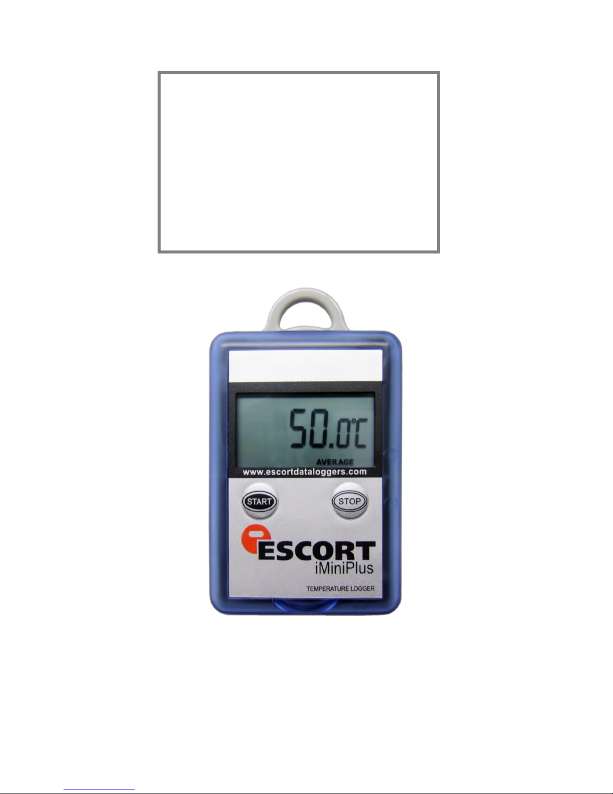
i M i n i P l u s
U S E R M A N U A L
Version 2.12.07MP
Copyright © 2016 Cryopak Verification Technologies, Inc. All rights reserved.
iMiniPlus User Manual Version 2.12.07MP
Page 2

The information contained within this document regarding ConsolePro software usage is
intended as a guide and does not constitute a declaration of performance. The information
contained in this document is subject to change without notice. Complying with all applicable
copyright laws is the responsibility of the user.
No representation or warranty is given and no liability is assumed by Cryopak Verification
Technologies, Inc. with respect to the accuracy or use of such information or infringement of
patents or other intellectual property rights arising from such use or otherwise.
Copyright © 2016 Cryopak Verification Technologies, Inc. All rights reserved.
www.cryopak.com
Page 3

i Contents
Contents
1. Introduction 5
Software Version .................................................................................................................. 5
2. iMiniPlus Profile 5
iMiniPlus Models ................................................................................................................... 5
iMiniPlus Images ................................................................................................................... 5
System requirements ............................................................................................................ 7
Getting a copy of the ConsolePro software ............................................................................. 8
Installing the USB adaptor cable drivers ............................................................................... 10
Getting a copy of the USB drivers from the web ................................................................... 11
Installing USB Driver Files using Found New Hardware Wizard .............................................. 12
Installing ConsolePro Software ............................................................................................ 12
4. Quick Start Guide 13
Connecting the serial or USB cable to PC .............................................................................. 14
Connecting the serial or USB cable to the iMiniPlus ............................................................... 14
Launching the software ....................................................................................................... 15
Starting and using the iMiniPlus ........................................................................................... 19
Stopping the iMiniPlus ......................................................................................................... 20
Retrieve information from the iMiniPlus ................................................................................ 20
5. Preparing iMiniPlus for use 23
Getting an iMiniPlus ready for logging .................................................................................. 23
Password Requirements ...................................................................................................... 24
Program and Configuration Wizard....................................................................................... 24
Details and Changing Password ........................................................................................... 25
Configure Sensors and Alarm Settings .................................................................................. 25
Specification and Alarm ............................................................................................. 26
Alarm Type ............................................................................................................... 26
iMiniPlus Display ........................................................................................................ 28
Enable Display .......................................................................................................... 28
Display Units of measurement .................................................................................... 28
Display change rate ................................................................................................... 28
Checking the time clock ...................................................................................................... 29
Setting the Start, Stop and logging duration ......................................................................... 29
Duration of trip, at least............................................................................................. 29
Interval between each reading ................................................................................... 29
Start new log trip ...................................................................................................... 30
Finish log trip ............................................................................................................ 30
Continuous logging .................................................................................................... 30
Enable stop button in this logger(s) ............................................................................ 30
Page 4
ii Contents
Summary and Upload Program into iMiniPlus ........................................................................ 30
Program upload Failure ....................................................................................................... 32
6. Results from iMiniPlus 32
Getting results from iMiniPlus .............................................................................................. 32
Download Wizard ................................................................................................................ 33
Inspecting the information at close range ............................................................................. 35
View Manager..................................................................................................................... 35
Views ....................................................................................................................... 36
Links ........................................................................................................................ 38
Multiple Trip Synchronization Wizard .......................................................................... 39
Analysis .................................................................................................................... 40
View Data in a Graph .......................................................................................................... 43
Data ......................................................................................................................... 44
Sensors .................................................................................................................... 45
2D Graphs ................................................................................................................ 45
Zoom ........................................................................................................................ 46
Legend ..................................................................................................................... 47
Time Zone ................................................................................................................ 47
Colors ....................................................................................................................... 47
Printing the results .............................................................................................................. 48
Sending a file by e-mail direct from Console ......................................................................... 48
Calling up previous results ................................................................................................... 48
Digital signatures ................................................................................................................ 48
7. Customizing the software 48
General .............................................................................................................................. 49
File .................................................................................................................................... 50
Date .................................................................................................................................. 50
Time .................................................................................................................................. 51
Time zones ......................................................................................................................... 51
2D Graphs .......................................................................................................................... 51
Legend ............................................................................................................................... 52
Products ............................................................................................................................. 53
Communications ................................................................................................................. 53
Languages ......................................................................................................................... 53
Colors ................................................................................................................................ 54
Advanced ........................................................................................................................... 54
8. Menus and Toolbars 55
Menu commands ................................................................................................................ 56
File Menu .................................................................................................................. 56
Edit Menu ................................................................................................................. 57
Action Menu .............................................................................................................. 59
Window Menu ........................................................................................................... 59
Help Menu ................................................................................................................ 60
Page 5

Contents iii
Toolbar commands ............................................................................................................. 60
Status bar .......................................................................................................................... 61
Print preview toolbar ........................................................................................................... 61
9. Working with Networks 62
10.
11.
12.
13.
Getting more information 62
Getting updated software .................................................................................................... 62
Finding your software version .............................................................................................. 62
Warranty 62
Dry Ice iMiniPlus 63
Specifications ..................................................................................................................... 63
Appendix 64
Troubleshooting .................................................................................................................. 64
Changing the Battery .......................................................................................................... 64
14.
Contact details 65
Page 6

Page 7
5
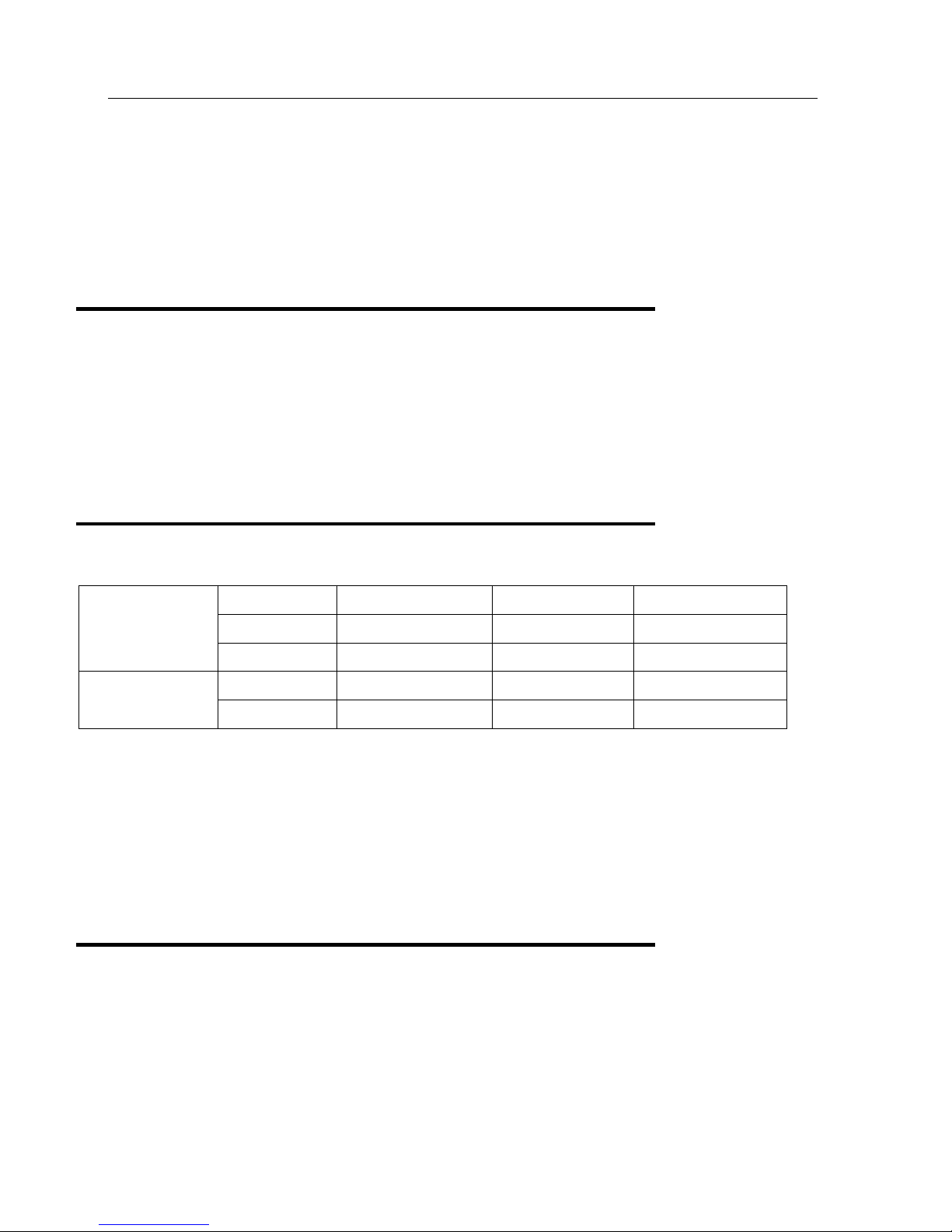
D range
MP-ST-D-8-L
Internal sensor
Single use
-40°C to +70°C
N range (Dry Ice)
Single use
-100°C to +40°C
-100°C to +40°C
1. Introduction
This user manual will take you through the relevant steps so that you will be able to operate your iMiniPlus product.
The chapters in this manual are placed in an order that you will need to follow in order to successfully use the iMiniPlus for
the first time.
This manual covers all the features included in the current version of the ConsolePro software. Therefore, if you find a
feature described within this manual that does not appear in your software and/or a feature within the version of software
being used that is not described in this guide, then we recommend you obtain a newer version of the software and/or a
newer version of this guide
Software Version
v2.12.07
Note: This User Manual is to be used with the above version software (or later) only. If you are using ConsolePro software
version earlier than the above, the content, instruction and features described herein may not be the same. Contact Cryopak
Verification Technologies, Inc. or your nearest distributor for appropriate software and user manual.
2. iMiniPlus Profile
iMiniPlus Models
The iMiniPlus is available in three models.
MP-IN-D-8-L
MP-OE-D-8-L External sensor Multi use -40°C to +70°C
MP-ST-N-8-L External sensor
MP-OE-N-8-L External sensor
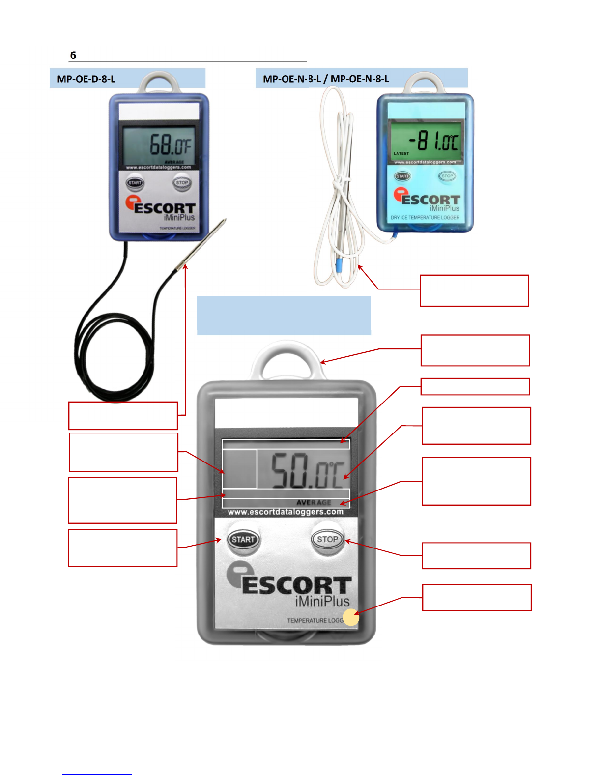
Internal sensor model has the sensor mounted inside the logger but externalized to the air to allow free movement of air
media across the thermistor head (Model MP-IN-D-8-L)
The other model comes with the same sensor as above but encapsulated inside a stainless steel tip on a 1meter PVC cable.
This sensor assembly is permanently connected to the body of the iMiniPlus (Model MP-OE-D-8-L/ MP-OE-N-8-L / MPST-N-8-L)
The iMiniPlus has a fully functional LCD display and keypad. A summary of these features and functions are summarised
below.
iMiniPlus Images
Internal sensor Multi use -40°C to +70°C
Multi use
Page 8
6
MP-OE-N-8-L / MP-OE-N-8-L
MP-OE-D-8-L
MP-ST-D-8-L
Attachment lug
Low Battery Icon
Temperature
HIGHEST LOWEST
STOP Button
Hold for 3 seconds.
START Button
LATEST - Displays the
activation
External sensor
Temperature sensor
Is here
For Dry Ice logger
MP-IN-D-8-L
External sensor
For D range
HIGH ALARM
LOW ALARM
alarm has been triggered
last logged temperature
MARKED – Bookmark
start, mark and scroll
functions
For fixing to item or wall
Latest, Highest, Lowest or
Average
AVERAGE
Displays the high, low and
average recording
Page 9
iMiniPlus Profile 7
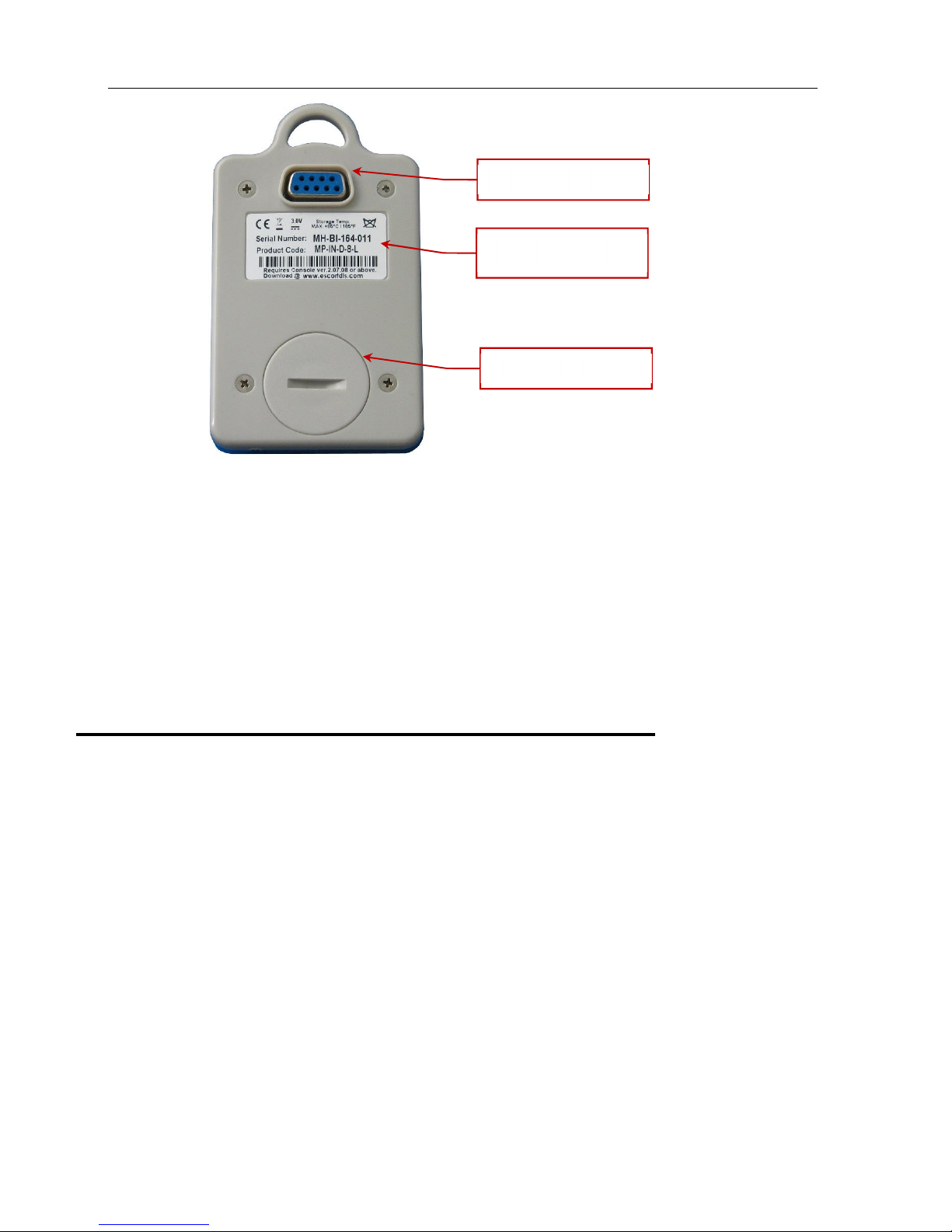
RS232 connection
Identification sticker
with barcode
Battery cover
The iMiniPlus comes with water-proof covers for the RS232 connection and the battery.
Make sure that when logger is in use these covers are in place. This is important in wet or dusty environments. If covers are
lost please contact your distributor for a replacement.
3. Installing the Software & USB driver
To operate your iMiniPlus logger you will need to first install the software on your computer. This will allow you to prepare
your iMiniPlus for use, retrieve the readings the iMiniPlus has recorded, and analyse the data. This chapter will take you
through the steps necessary to successful install the software on to your computer so you can begin using your iMiniPlus.
System requirements
To ensure that the software will be able work with your computer, the following lists the minimum specifications required:
Minimum requirements:
Pentium II 233MHz processor
64MB RAM
15MB free disk space
Windows 98, Windows Me, Windows NT, Windows 2000, Windows XP
Internet Explorer 5.0 or later
1 available USB port
800 x 600 screen resolution
256 screen colours.
The recommended specifications are:
Windows 2000, Windows XP, Windows Vista, Windows 7, 8, 8.1 or Windows 10
Internet Explorer 6.0 or later
65535 (16bit), or more, screen colours.
1024 x 768, or higher, screen resolution.
Page 10
8
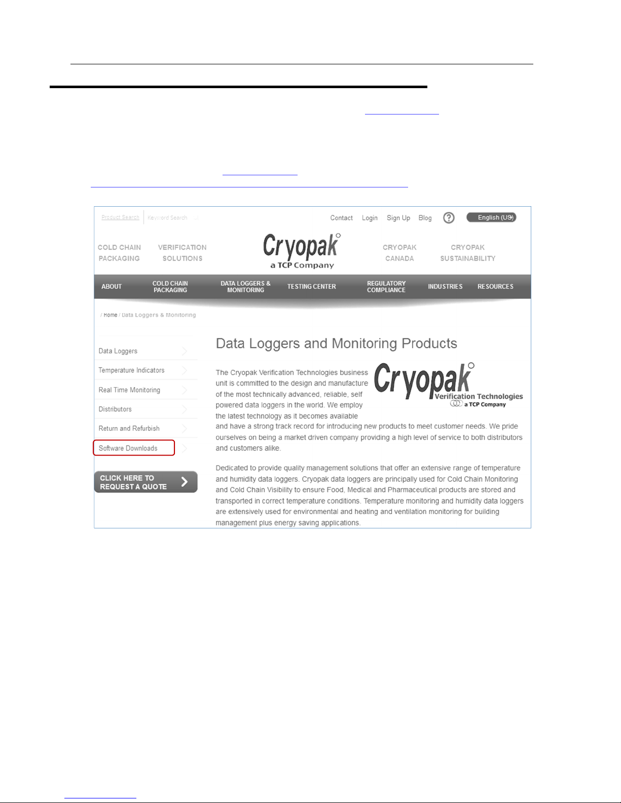
Getting a copy of the ConsolePro software
The software is available on CD from your distributor or downloadable from
does not charge for the on-line download of the ConsolePro software or for the updates to the ConsolePro software.
Install the free Console Pro Software using either
1. The Console Pro Software CD or
2. Through the CRYOAPK website
3.
http://www.cryopak.com/files/1613/7599/1145/econsole_21207pro.zip
4. See instructions below for Website Installation
www.cryopak.com
www.cryopak.com
site, Data Logging Systems
Page 11
iMiniPlus Profile 9
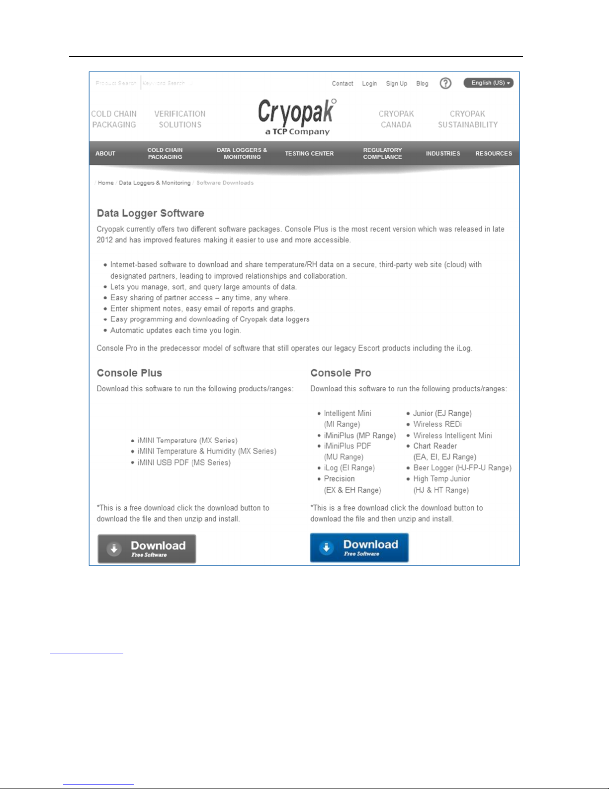
5. Once you have downloaded and installed the Console Pro Software, move on to the second phase of installation by
installing the USB Drivers.
For a more in depth guide to Console Po Installation, please refer to the user manual provided on the website:
www.cryopak.com
Page 12

10
We recommend choosing the option to save the file and to save the file to your desktop. If you are an experienced user, you
may wish to save the file to a different folder of your choosing. Once the installation process has been completed, this file
can be safely deleted, as it is not required for using the software.
At the conclusion of the installation process, the final screen will provide you with an option to immediately start the
ConsolePro software.
The installation of the ConsolePro software will also provide you with two simple methods to start the ConsolePro at a later
time:
A "Shortcut" on the desktop, which you can double click to start the software.
A "Shortcut" in the "Start" menu system. If you are using Windows XP for example, you may need to click on the "All
Programs" item to locate the "Console" shortcut.
Installing the USB adaptor cable drivers
To be able to operate the iMiniPlus with ConsolePro
Software, you have to connect the iMiniPlus to your
computer with a serial to USB or serial to serial adaptor.
A USB cable requires driver software for it to be used.
This software is supplied on mini CD format with the
adaptor or from web site www.cryopak.com
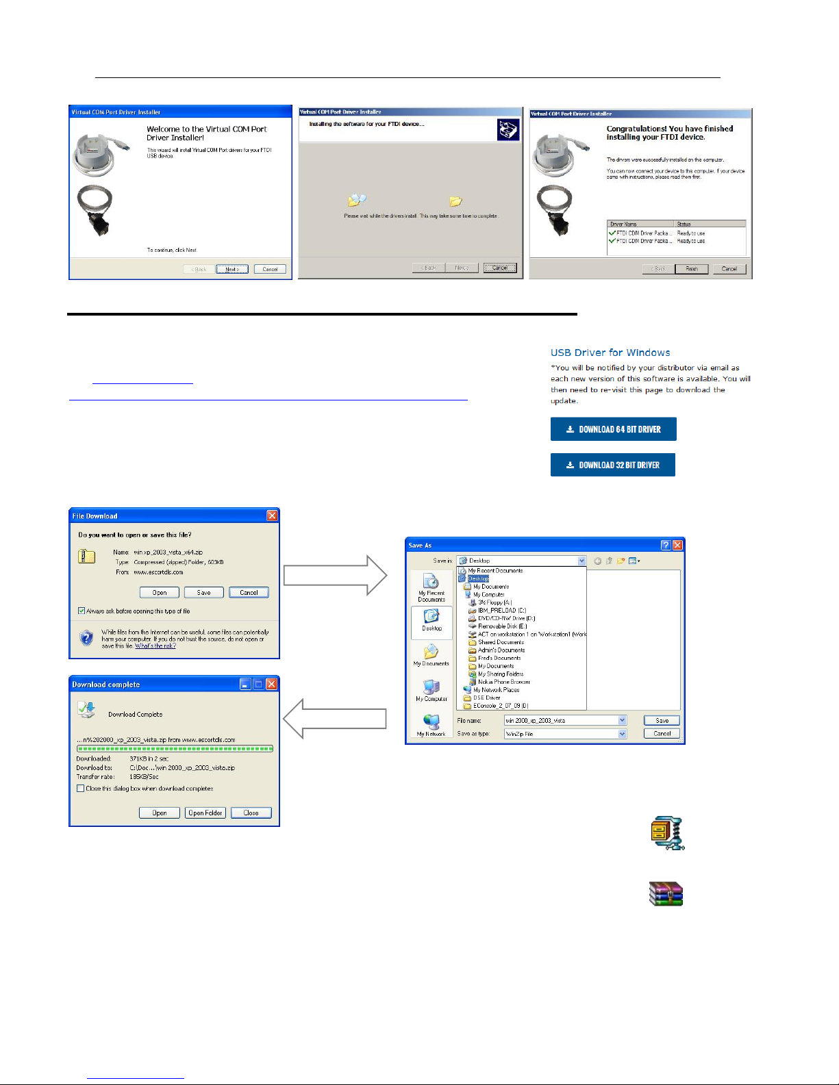
Insert the driver mini CD into your computer CD
ROM and the following screen box will be
displayed. Select Auto Install
Select Run.
Select Next.
Select Finish. Reboot your PC
and insert the USB cable. If this does
not work, you will have to install using
the “Found New Hardware Wizard” on
your computer Control Panel. See
next sections.
Page 13
iMiniPlus Profile 11
Select Desktop Select Desktop
Select close
Getting a copy of the USB drivers from the web
If you misplace the driver mini CD, you can obtain the driver files from our web
site www.cryopak.com
http://www.cryopak.com/temperature-monitors/software-downloads/
Here you can
On the Software Download page, you will see a list of driver file USB driver for
windows. Download the appropriate driver file for your Windows operating system
and save to your desktop. Please note the file is in ZIP (compressed) format.
Select save.
Because the file is in compressed (ZIP) format, you will have to extract it into another
folder. The file icon on your desktop may look like one of these:
Double click on the ZIP icon and extract all the files into a new folder and name it USB
Drivers. Once the files are extracted you can delete the original ZIP file if you like.
win 2000_xp_2003_vista.zip
win xp_2003_vista_x64.zip
Page 14
12
Installing USB Driver Files using Found New Hardware Wizard
If you have experienced a problem installing your USB drivers using the original instructions, you can install either the mini
CD or the extracted ZIP file you have downloaded as detailed in the previous chapter, via the “Found New Hardware Wizard”
in your computer Control Panel.
In some events if the driver is unable to install, user may require to extract the *.exe file with winrar software in a folder and
by browsing the device driver update wizard to the that folder
Note: User must have ADMIN rights to install driver and Console Pro software
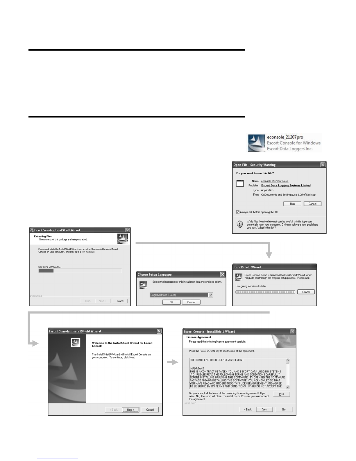
Installing ConsolePro Software
Note: User must have ADMIN rights to install driver and Console Pro software
To install the ConsolePro software, first you need to locate the installation file that was
downloaded from the Cryopak website or from CD received when purchased.
To begin the installation process, open the installation file, which is typically
performed by double clicking the left mouse button. The installation process will
guide you through the relevant steps to correctly and successfully install the
software. If you have installed any other software, you should find the installation
process familiar. To proceed through each step of the installation process, click the
"Next" button. If you want to change a previous step you can click the "Back"
button. When the process is ready to be completed, clicking the "Finish" button,
when it appears, will finish the installation process. If you want to stop installing the
software, click the "Cancel" button.
Page 15

Quick Start Guide 13
Note:
This
section
relates to
additional
software
called “User
Admin”
which is
designed to
comply with
CFR 21 Part
11
specification.
If you are not
using this
software
ignore this
step and
select Next.
At the conclusion of the installation process, the final screen will provide you with an option to immediately start the
ConsolePro software. The installation of the ConsolePro software will also provide you with two simple methods to start the
ConsolePro at a later time, which are a "Shortcut" on the desktop, which you can double click to start the software and a
"Shortcut" in the "Start" menu system. If you are using Windows XP for example, you may need to click on the "All
Programs" item to locate the "Console" shortcut.
4. Quick Start Guide
Now you have the software and drivers installed on your computer, you can start to use the iMiniPlus. This chapter will
briefly cover the steps involved to get your iMiniPlus ready to use, how to get it started and then retrieve the recorded
information. The subsequent chapters will explain in more depth these steps and the various options available to you.
Page 16
14
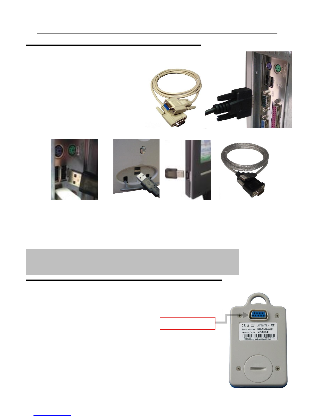
Connecting the serial or USB cable to PC
The connectors for the serial (RS232) communications ports typically look like
the following picture.
Serial (RS232) communication ports can be typically
found at the rear of the computer. Most serial
connectors will have screws included on the plug and
we recommend that these are tightened when the
connector is plugged in so that it does not accidentally
pull out during use.
Some of the more common USB connectors are
pictured below.
Connectors for USB devices and the sockets on the computer where USB devices are plugged in will often display a USB logo
nearby to help them be identified.
The sockets for the USB communication ports are typically located at the rear of the computer. In some computers there may
also be two or more USB communication ports located on a front panel of the computer and/or on the top of the computer
case. Please ensure that the driver software has been installed prior to connecting the USB cable.
If the computer is using the Windows NT® operating system, a USB cable will not be able to be used, as Windows NT® does
not support USB devices.
Important notes:
Ensure to select manual the COM port before download and program the unit
If using USB to serial adaptor the COM port # will be COM3 or higher
If using Serial to serial interface the COM port # will be either COM1 or COM2
Connecting the serial or USB cable to the iMiniPlus
The iMiniPlus has a serial DB9 connection on the rear. Connect either the serial cable or
USB cable DB9 male connector to this. Make sure that the connector is pushed in, making
the connection tight and not loose.
RS232 DB9 connection
Page 17
Quick Start Guide 15
Launching the software
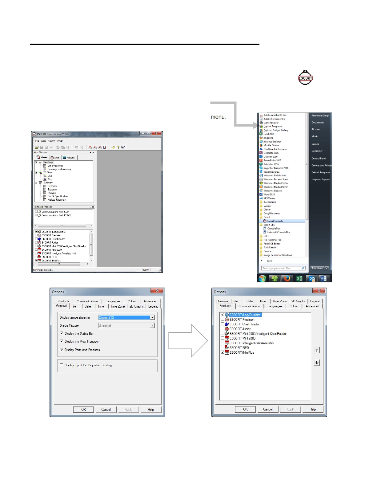
The installation of the ConsolePro software provides you with two simple methods to start the Console:
1. A "Shortcut" on the desktop, which you can double click to start the software.
2. A "Shortcut" in the "Start" menu system.
If you are using Windows XP for example, you may need to click on the "All Programs" item
to locate the "Console" shortcut, like in the following picture.
3. To program the iMiniPlus to record information,
Launch the ConsolePro software from the desktop or All Programs menu.
The software will open and display the following screen:
Escort Console
From the menu, select Edit, then Options
Select the
Products Tab
In the Products tab you will see a list of all the products supported by the ConsolePro Software. Make sure the “iMiniPlus”
box is ticked and click on OK or Apply. If you intend to use other products, you may tick as many of the boxes you require.
Next make sure you have selected the correct Communications Port. Note that the USB cable needs to be connected to the
PC before you start the ConsolePro Software otherwise it won’t show on the list below. Click on OK or Apply.
Page 18
16
If your software
locate a logger
communication
Check that
MP D range MP Dry Ice
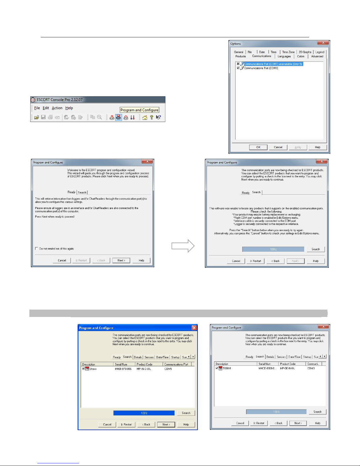
Both the Products and Communications Ports can be selected through the Ports
and Products just below the View Manager on the left hand side of the initial
software page.
Next click on the Program and Configure icon that is located on the toolbar.
The Program and Configuration Wizard finds the communication port that the
iMiniPlus is connected to enable it to be setup for use.
is unable to
due to
Check that all four bullet points displayed in this message are attended to. Once rectified either close the ConsolePro
software and reopen or select the Restart button if the software was left open. If this problem continues, please consult your
nearest distributor or contact Data Logging Systems.
Once your software has located a logger the window will display the loggers’ description, serial number, product code and
communications Port. To proceed select the Next button.
the
description
box is ticked
problems the
following
message will
be displayed.
Page 19
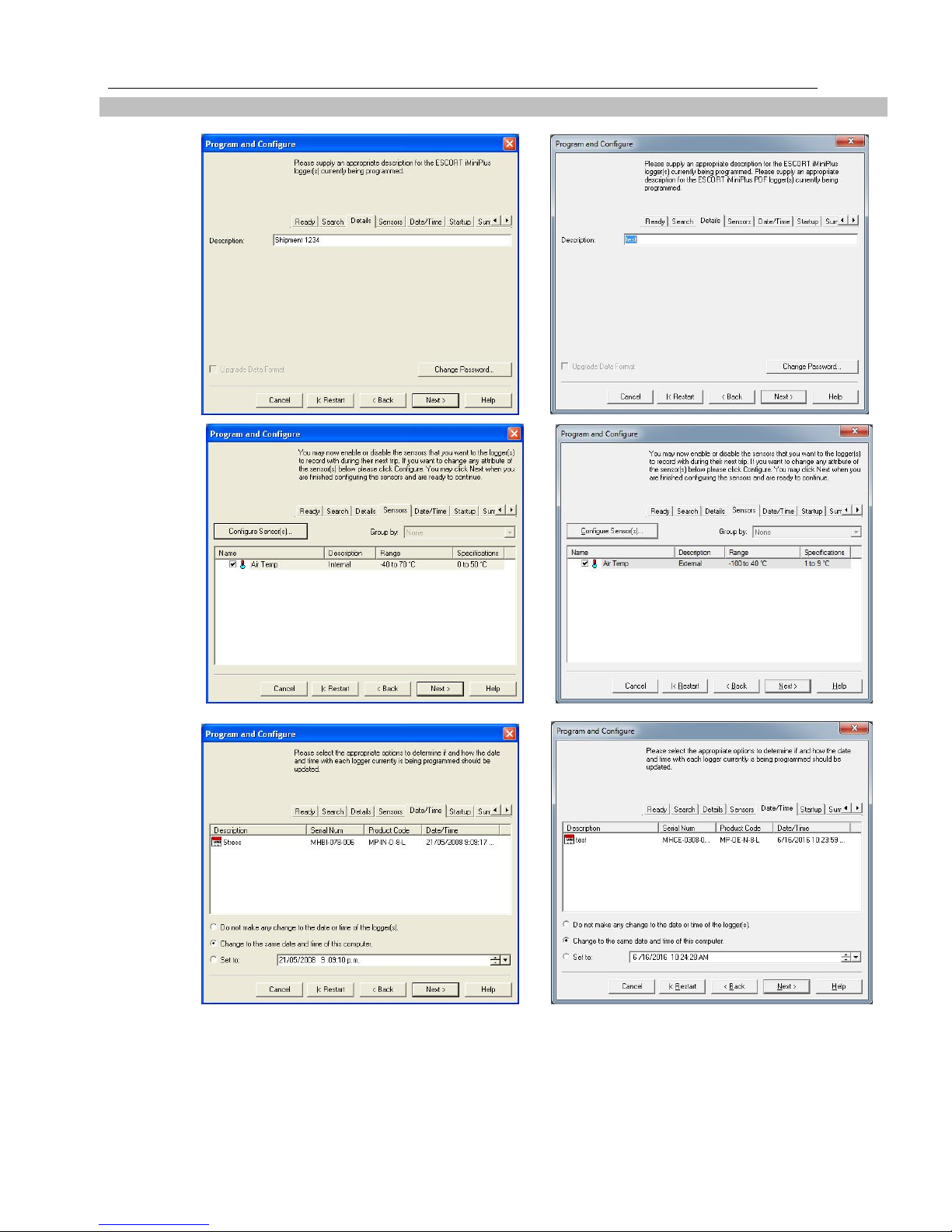
Quick Start Guide 17
Select the
MP D range MP Dry Ice
Enter a
Select Next
tab.
Check that
Next button
or Details
tab.
description
of the
temperature
application
in the 24
characters’
box.
button or
Date/Time
the date and
time is
correct.
Select Next button or Startup tab.
Configure the start, recording and stop conditions.
Page 20
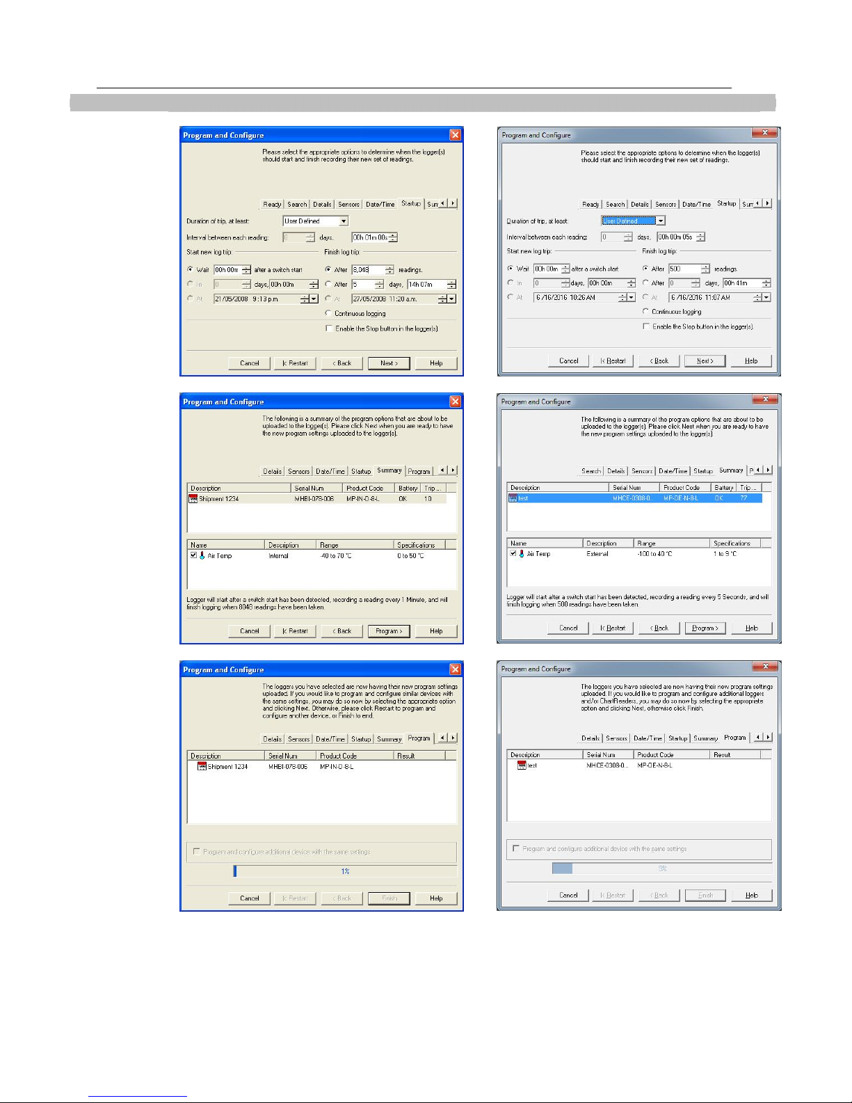
18
MP D range MP Dry Ice
Next
Select
Program
iMiniPlus
Select
button or
Summary
tab.
Check that
program
settings are
what you
want.
Program
button or
Program tab
conditions
are being
uploaded to
Page 21
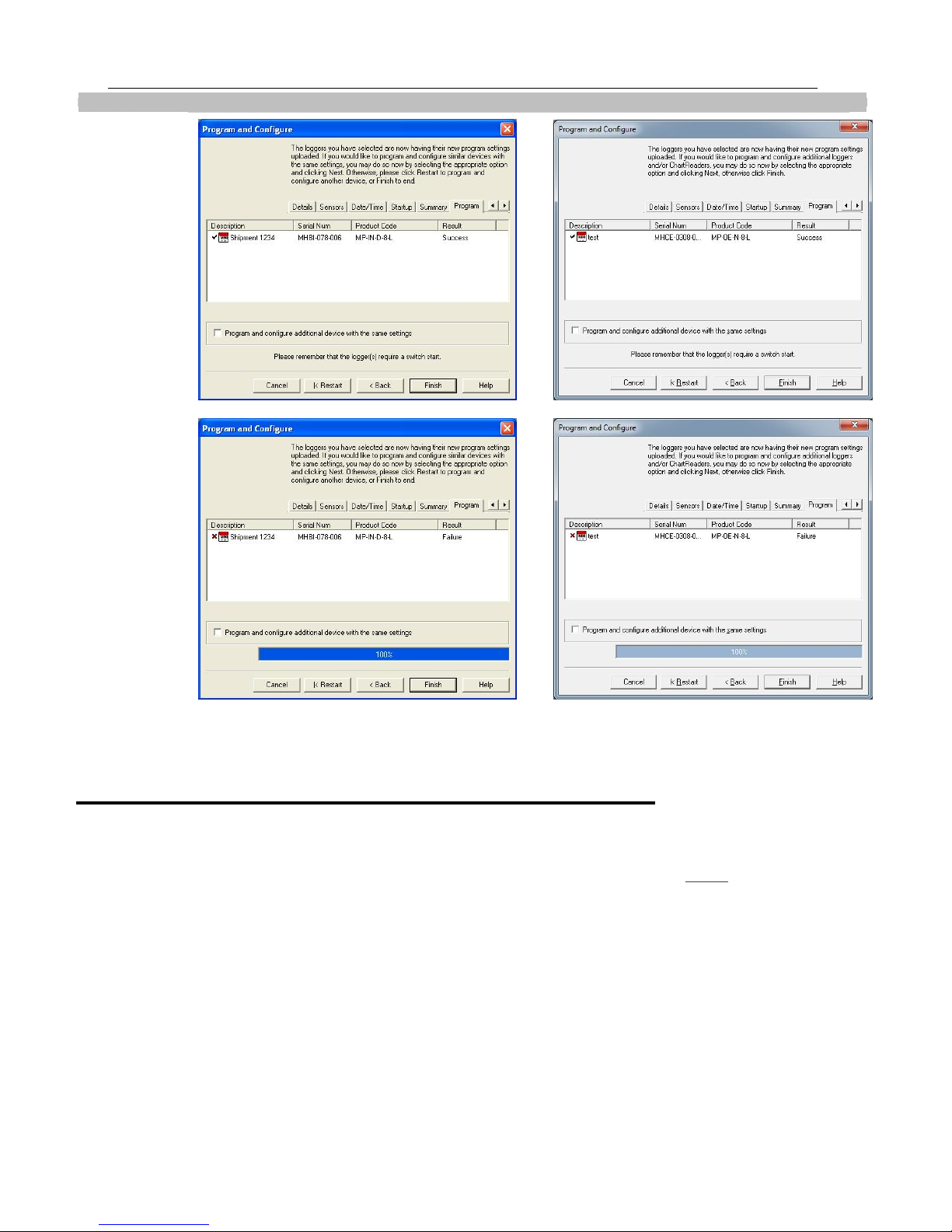
Quick Start Guide 19
MP D range MP Dry Ice
The
Select the Finish
button
conditions have
the iMiniPlus.
iMiniPlus has
been
correctly
programmed
!
Program
successfully
uploaded into
If the upload has failed either select the Cancel button to close the software and start again or select the Restart button to
start the sequence again. If the iMiniPlus still fails to upload, contact your local distributor or Cryopak Verification
Technologies, Inc.
Starting and using the iMiniPlus
Once an iMiniPlus has been successfully programmed for use it is ready to be started. It will have the word “READY”
displayed in the top left of the screen. If it has any different information displayed, the iMiniPlus cannot be started.
To activate the iMiniPlus press and hold the START button until the display changes to a series if dashed lines and then the
temperature reading.
If a delayed start has been programmed, the word “IN DELAY” will be displayed in the top middle of the screen, until such
time as the iMiniPlus starts logging. At that time the temperature will be displayed.
During operation the last logged temperature will be displayed on the screen with the word “LATEST” flashing in the bottom
left of the screen.
By pressing the Start button during logging, the “HIGHEST”, “LOWEST” and “AVERAGE” temperature to date will be
displayed in succession and the bottom of the screen.
By pressing the Start button again, the words “HIGH ALARM” and LOW ALARM” will flash in succession and the time
outside the alarm threshold will also be display.
not been
Page 22
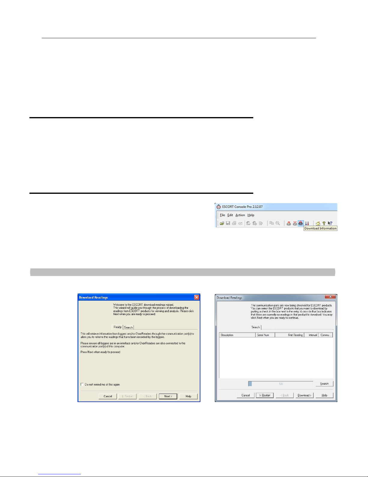
20
MP D range MP Dry Ice
By pressing the Start button a third time, the display will return to the Latest reading.
The display will always return to the Latest reading after a 1 minute if the Start button is not pressed.
You can also have the iMiniPlus record a “bookmark” at any time while it is recording, simply by pressing and holding the
Start button for 2 seconds. The word “MARKED” will be displayed at the bottom of the screen.
If the iMiniPlus has stopped recording then the bookmark feature cannot be used.
See the section
iMiniPlus Profile
at the beginning of this guide for a full description of the display and button functions.
Stopping the iMiniPlus
The iMiniPlus can be stopped only if this has been enabled in the program conditions. (See Opening the Software section).
To stop the iMiniPlus press the Stop button and hold for 2 seconds, the word “STOPPED” will be displayed in the top right
corner.
If the Start button is pressed the Latest reading will be displayed and subsequent pressing of the Start button will result in the
Highest, Lowest, Average and Alarm conditions being displayed as before.
However, after 1 minute of continuous display of either feature, the display will always return to show the word “STOPPED”.
Retrieve information from the iMiniPlus
When you are ready to view the recordings that are stored in the
iMiniPlus, connect it to the USB or serial cable and connect the cable to
your PC as before. If the iMiniPlus is still logging when you go to
download the readings it will continue to record without interruption so
you will be able to download again later if you choose.
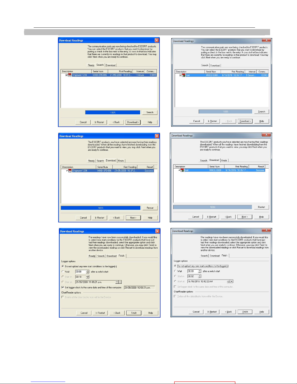
Open the ConsolePro Software as previously described and click on the Download icon.
In the “Download Readings” Select the Next button or Search tab.
Select the Download button or tab.
Page 23
Quick Start Guide 21
MP D range MP Dry Ice
Select the
Select
Next
button or
Finish tab.
the
Finish
button
.
Page 24
22
MP D range MP Dry Ice
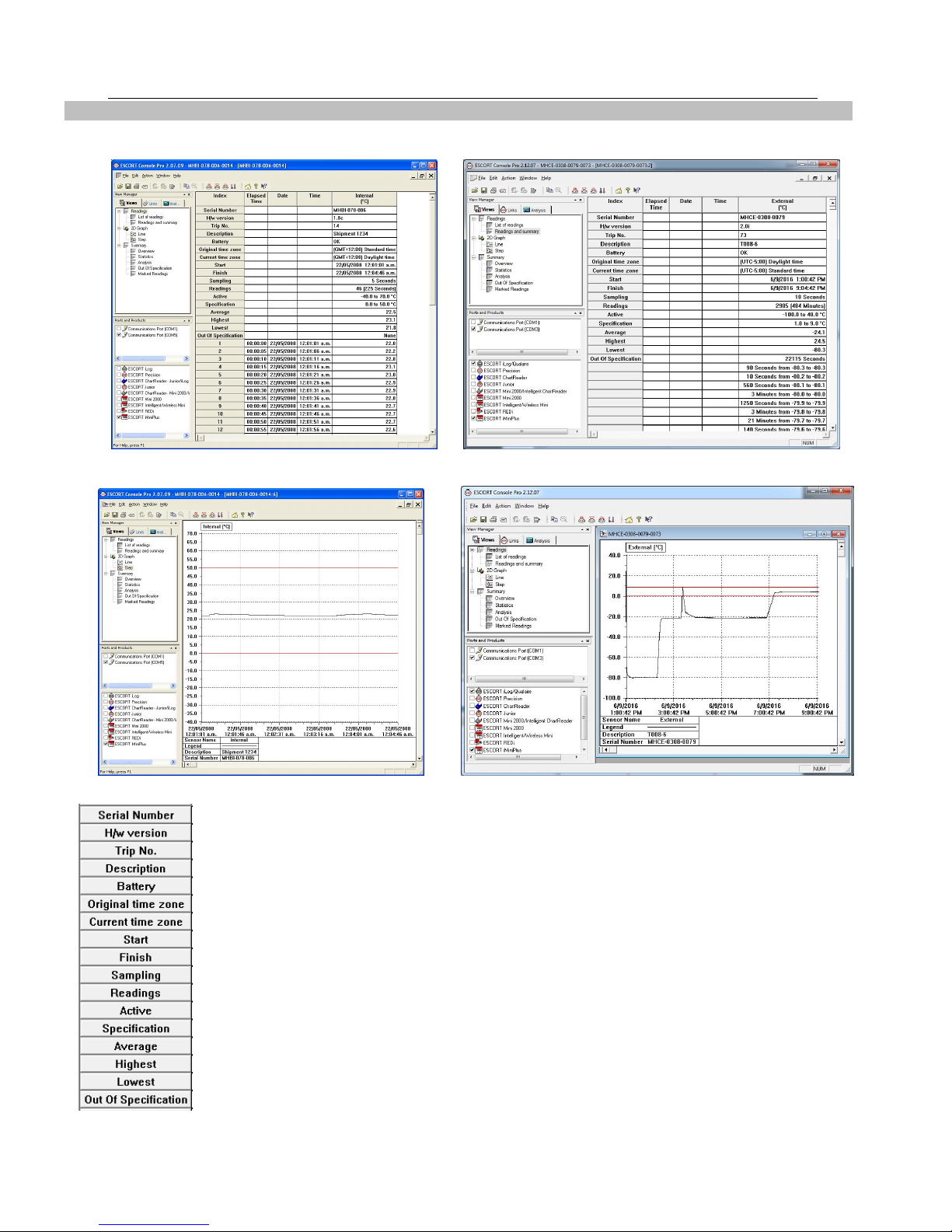
Readings and Summary is displayed.
Select the 2D Graph from the View Manager to show data in graphical form.
Following information of a logger is displayed
Save the data file for a permanent record. The data is saved by default to a folder called
“My Logger Data” in the “My Documents” folder on your computer. You can change this
destination if you prefer it to be saved for instance to a shared network drive. See
Chapter
as a result of downloading the iMiniPlus.
Data from iMiniPlus
that explains in more detail the information that is displayed
Page 25
23
5. Preparing iMiniPlus for use
Before you can start using an iMiniPlus to log the environment you must first prepare it for use. The
process of preparing an iMiniPlus for use allows you to define a number of parameters, including:
How long it should log the environmental condition for, so that you can be assured that it will record for
the duration of time required? For example, if you want it to record the temperatures of a shipment that
will take 25 days to deliver, you will be able to make sure it will record the temperatures throughout
the entire 25-day period.
How often it should log the environmental conditions?
Under what conditions it should display an alarm? An alarm indicates when the environment being
logged is not within programmed limits.
This section explains how to prepare an iMiniPlus for use and what the options mean.
Getting an iMiniPlus ready for logging
Make sure the USB or serial cable is connected to your PC and to the iMiniPlus.
After you have opened the ConsolePro Software (
Software
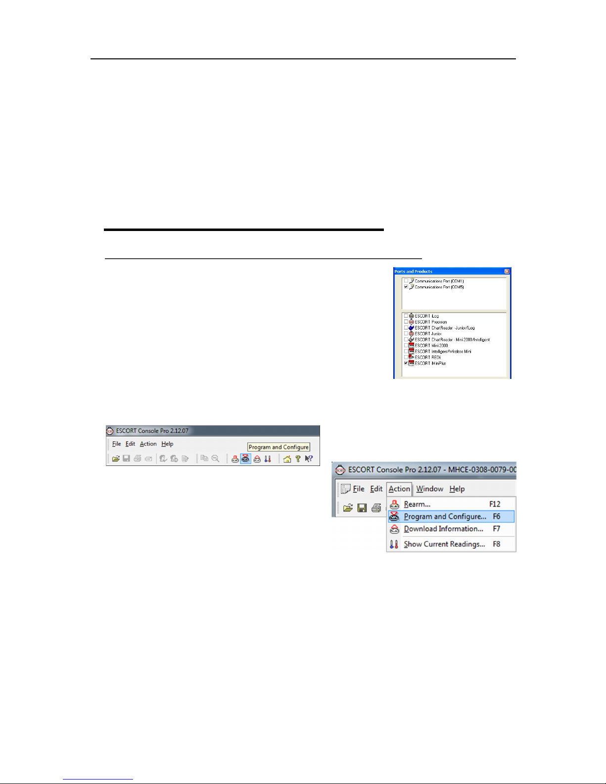
iMiniPlus from the list of products. If these are not selected the iMiniPlus
will fail to communicate with the software.
You can only select one COM port at a time and if the iMiniPlus fails to
communicate with the software, select another.
Please note that you must connect the USB cable before you open
ConsolePro software. If you open the software first, then connect the
cable, the software will fail to recognize it and the COM port will be
omitted from the list.
There are two ways to prepare an iMiniPlus for use, both of which will
achieve the same result.
) it is necessary to select the correct COM port and the
Click the Program and Configure icon on the toolbar
see section Opening
Click the "Program and Configure..." item located under
the Action menu.
Once an iMiniPlus has been through the Program and
Configuration process to get it ready for next use, any
readings previously recorded will no longer be available
for retrieval
Page 26
24
Password Requirements
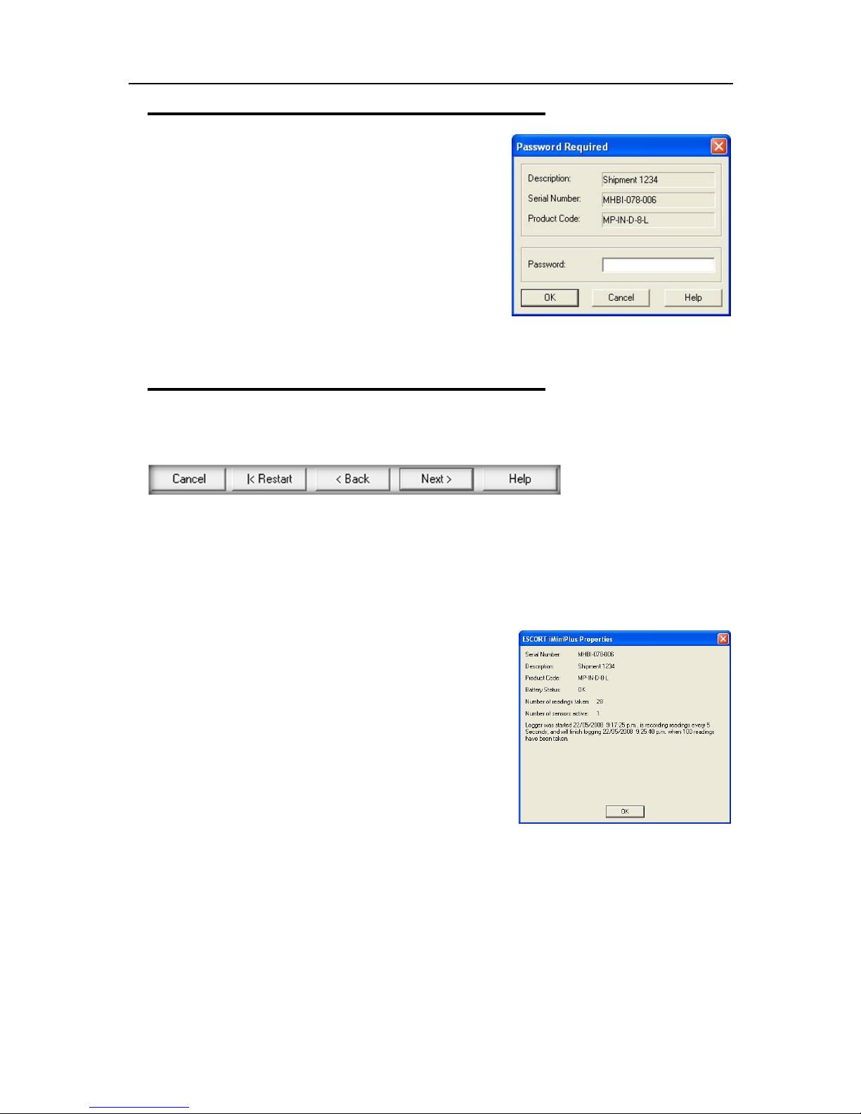
The iMiniPlus supports password option that, when enabled,
results in users being required to provide the correct password
to gain further access to the iMiniPlus. When the password
option is enabled, a window similar to the following picture will
be displayed allowing the user to enter the correct password.
The Program and Configure process will only continue
successfully if the correct password is supplied by the user.
Passwords are digits only, up to 4 characters.
You can enter a password to safeguard your logger from
unauthorized tampering. Make sure that you keep a note of your
password and logger serial number in a safe place. If you lose or forget the security code, the logger will
have to be returned to your nearest distributor or Data Logging Systems to restore default password.
Program and Configuration Wizard
During the progress of the Program and Configuration Wizard, you will see a series of 5 buttons at the
bottom of the wizard box.
The “Cancel” button immediately stops and closes the wizard. To start again you will have to select the
Program icon. The “Restart” button enables you to start the Wizard progress from the beginning without
closing the feature. “Back” enables you to go back one step in the step-by- step progress and Next takes
you to the next step. The Help button will provide description and instruction about the step you are in.
Please note that this feature may make reference to other products from time to time. Additionally some
Help documentation may not be present due to the software version you are currently using. Consult this
iMiniPlus manual if you are not sure about any description.
Search Tab – displays the description of the recorded
environment, iMiniPlus serial number, the iMiniPlus product code
and the communication port the iMiniPlus is connected to.
If a small green arrow is present, this signifies that the iMiniPlus is
still logging.
By double clicking on this description line, the iMiniPlus Properties
box can be displayed.
The properties box displays, serial number, description, product
code, battery status, no. of readings taken, active sensors and a
summary of the logging parameters.
If the description box is unticked, it means the password to protect program settings in the logger has been
set. You will have to click on the box and enter the password.
If there is a X in the description box, only the Search tab will be displayed and the Program and Configure
Wizard cannot proceed any further.
This may indicate a fault with either the software or iMiniPlus itself (for example, low battery or lease of the
current logger has expired). Consult your nearest distributor or Cryopak technical support team
Page 27
Preparing iMiniPlus for use 25
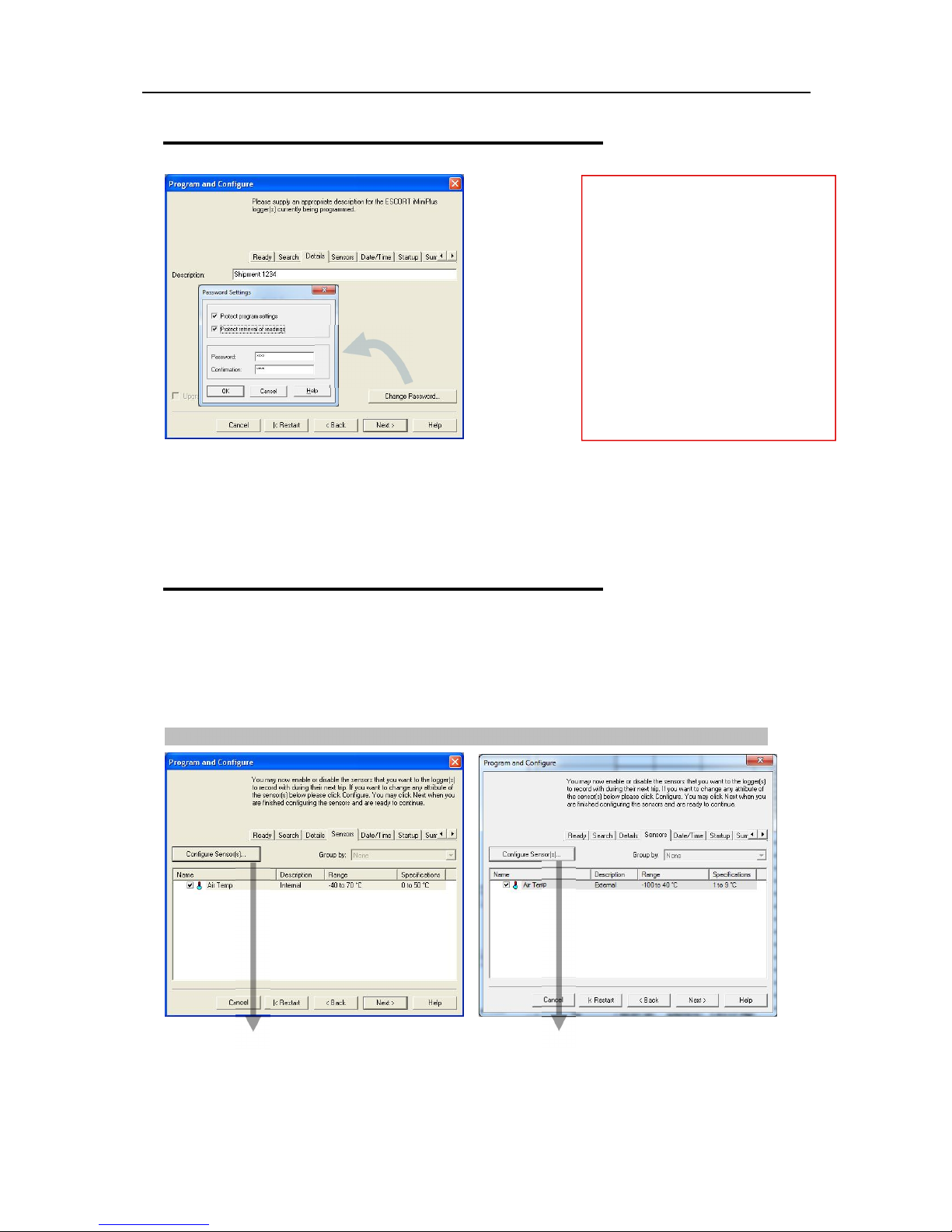
Details Tab - Enter a description of the
MP D range MP Dry Ice
Details and Changing Password
temperature application in the 24 characters’
box. This can be a location, product etc.
Change Password – if you have password
protected the iMiniPlus or are wanting to
add a password for the first time you can do
this here.
Protect program settings - Tick this option
if you want to protect your programming
settings for the current logger.
Protect retrieval of readings- Tick this
option to disallow viewing of data from the
current logger without a password.
Password are digits only, up to 4 characters.
Please keep your password safe and make sure no unauthorized person has access to it. If you forget your
password, the protection cannot be disabled and you will have to return the iMiniPlus to your nearest
distributor.
If you leave the password blank but enable the protection, to access the iMiniPlus just click OK in the
Password Required dialog.
Configure Sensors and Alarm Settings
Sensors Tab – this displays the sensor information some of which can be changed by using Configure
Sensor(s) and others that remain fixed i.e. range -40C to 70C. The description “Internal” refers to the
type of sensor as opposed to “External” which will display on the external sensor model.
Configure Sensor(s)… - click on this button to set up the alarm and LCD display parameters.
Page 28
26
MP D range MP Dry Ice
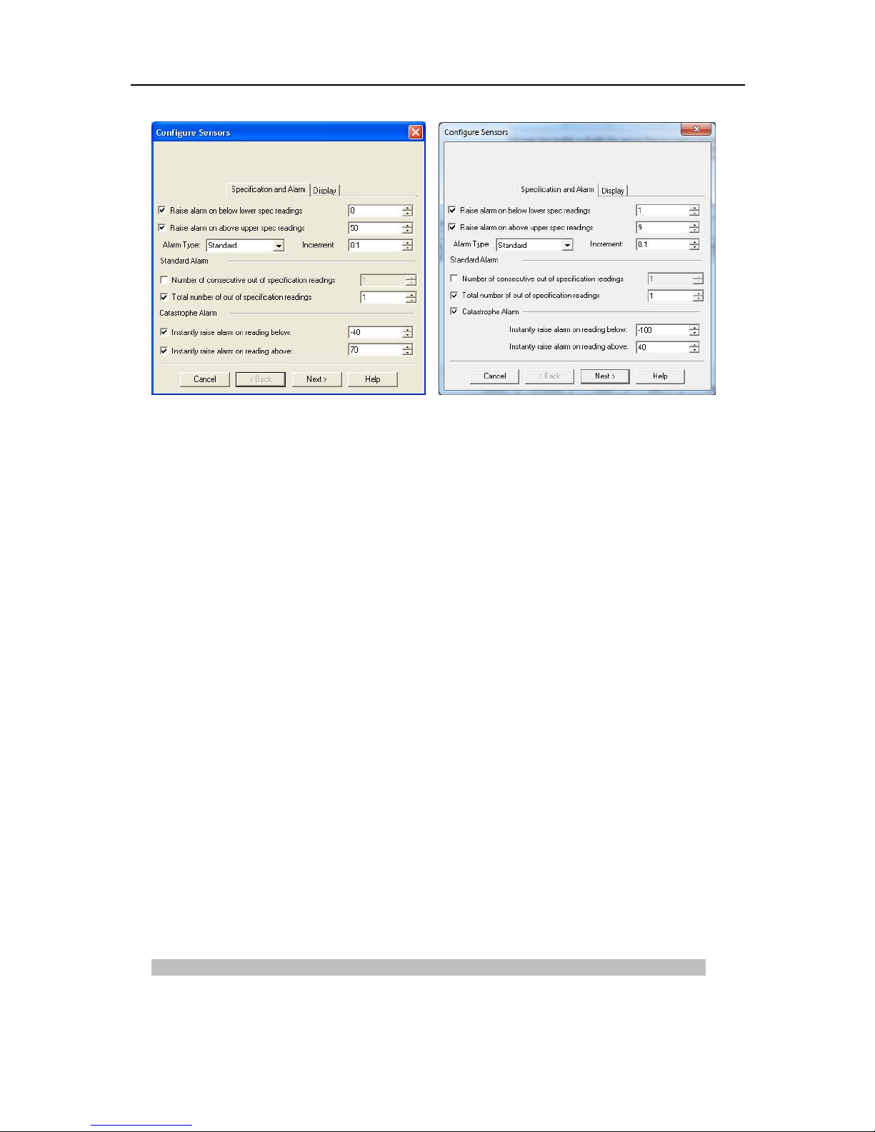
Specification and Alarm
Raise alarm on below lower spec readings – tick this box if you want to activate the low alarm and select
the value in the box immediately to the right. Note if the lower spec value is 0C, then the alarm can be
triggered at -0.1C, not 0.0C as this value is considered within specification.
Raise alarm on above upper spec readings – tick this box if you want to activate the high alarm and
select the value in the box immediately to the right. Note if the upper spec value is 50C, then the alarm
can be triggered at 50.1C, not 50.0C as this value is considered within specification.
Increment - the grouping size used for listing out-of-specification readings.
Alarm Type
This feature allows the user to specify the condition that will trigger an alarm.
Standard Alarm
Number of consecutive out of specification readings – the alarm is triggered if the readings are
consecutively over or under the specified threshold. For instance, if the upper spec is 50C and the value
for the number of consecutive out-of-spec readings is 3 and the logging interval is 10minutes, the readings
will need to be in excess of 50C for 30 minutes before the alarm is triggered. If the readings fluctuate
outside upper and lower threshold temperatures, the same rule applies (providing the appropriate “raise
alarm” box is ticked). Once reading(s) return inside alarm limits, the consecutive alarm is reset.
Total number of out of specification readings (cumulative) – the alarm is triggered if the total number of
out of spec readings equals the entered value. In this case the alarm is NOT reset if readings return to
within the specified parameters, and each out-of-spec reading is added to the previous one until the
number equals the entered value.
Do not set the Total number of out-of-spec readings value to be less than the Consecutive out-of-spec
readings as this will mean that the Consecutive out-of-spec readings alarm will never be triggered.
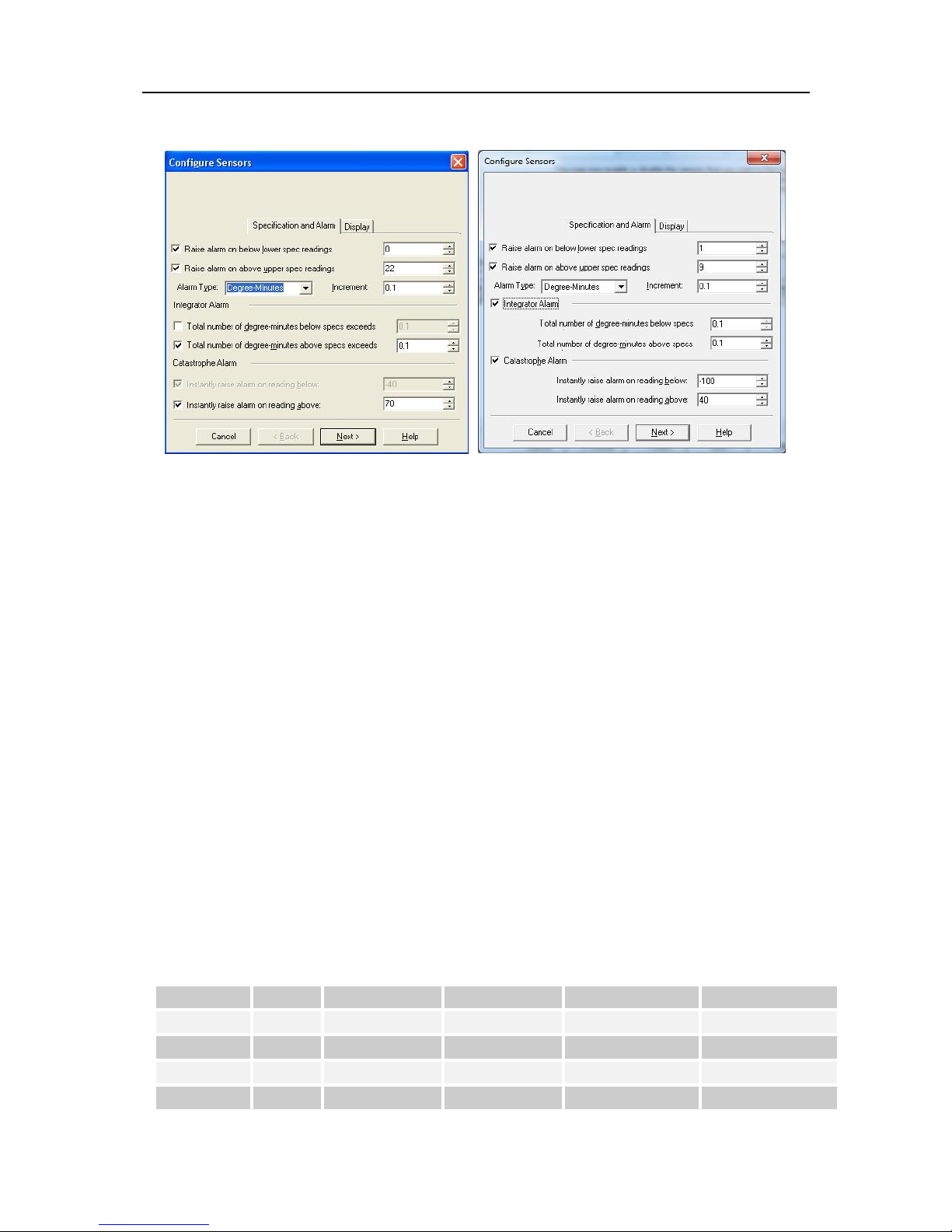
Degree-Minutes Alarm (Integrator Alarm)
The Degree-Minutes Alarm is a special feature that “integrates” temperature and time parameters into one
value.
Page 29
Preparing iMiniPlus for use 27
Total number of degree-minutes below specs exceeds - the alarm is triggered when the total number of
temperature degrees below the low alarm spec is greater than the value entered.
Total number of degree-minutes above specs exceeds - the alarm is triggered when the total number of
temperature degrees above the upper alarm spec is greater than the value entered.
Catastrophe Alarm
This alarm is always secondary to the Standard and Degree-Minute alarms and there is no delay. Do not
set Catastrophe Alarm inside normal alarm limits because other alarms will never be triggered.
Instantly raise alarm on readings below - tick this box if you want to immediately trigger the low alarm
and select the value in the box immediately to the right. Note if the lower spec value is 0C, then the alarm
can be triggered at -0.1C, not 0.0C as this value is considered within specification.
Instantly raise alarm on readings above - tick this box if you want to immediately trigger the high alarm
and select the value in the box immediately to the right. Note if the upper spec value is 50C, then the
alarm can be triggered at 50.1C, not 50.0C as this value is considered within specification.
The table below demonstrates arbitrary data from an iMiniPlus and how different alarm sources will be
triggered. This is complicated scenario for alarm settings based on:
Upper spec alarm: +20C
Number of Consecutive out of spec readings: 4
Total number of out of spec readings: 5
Total number of degree-minutes above specs exceeds: 8
Instantly raise alarm on readings above: +23C
Time [min] T [ º C] Consecutive Total Integrator Catastrophe
0 19 OFF / 0 OFF / 0 OFF/0 OFF
1 20 OFF / 0 OFF / 0 OFF/0 OFF
2 23 OFF / 1 OFF / 1 OFF/3 ALARM ON
3 21 OFF / 2 OFF / 2 OFF/4 ALARM ON
Page 30
28
MP D range MP Dry Ice
4 19 OFF / 0 OFF / 2 OFF/4 ALARM ON
5 21 OFF / 1 OFF / 3 OFF/5 ALARM ON
6 22 OFF / 2 OFF / 4 OFF/7 ALARM ON
7 24 OFF / 3 OFF /5 ALARM ON /11 ALARM ON
8 22 OFF / 4 ALARM ON /6 ALARM ON /13 ALARM ON
9 21 ALARM ON /5 ALARM ON /7 ALARM ON /14 ALARM ON
10 19 ALARM ON/0 ALARM ON /7 ALARM ON /14 ALARM ON
iMiniPlus Display
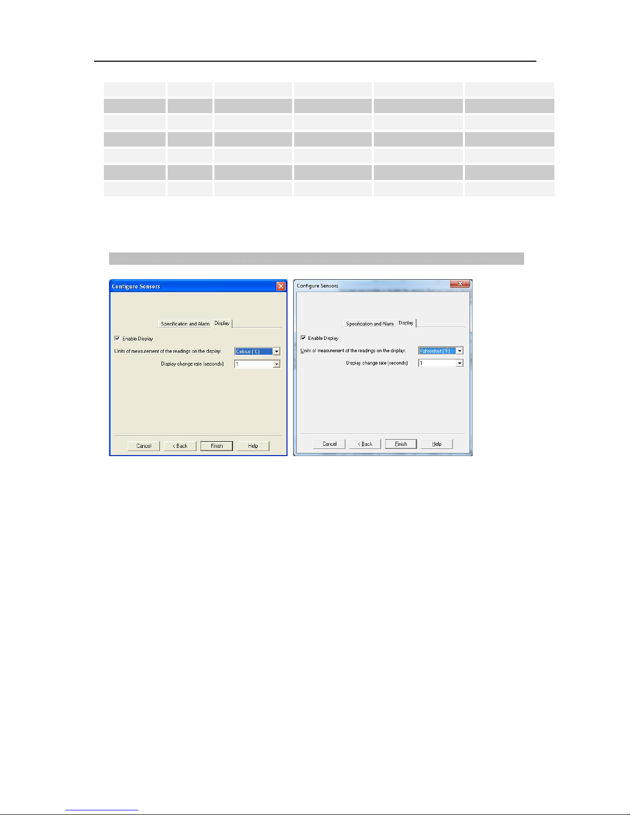
The iMiniPlus LCD can be configured to display or not display the temperature information.
Enable Display
Tick this box if you want to enable the display to show the temperature readings and statistics.
If the box is un-ticked, all other features will be greyed out. The iMiniPlus LCD will show “d-off” instead of
a temperature value. Additionally you will not be able to scroll through the highest lowest, average and out
of spec readings. The word “LATEST” will flash and if any alarm had been triggered, “HIGH ALARM” or
“LOW ALARM” will be displayed.
The bookmarking function can still be used when the display is disabled.
When the iMiniPlus is stopped using the Stop button or it stops because it has reached the end of a
logging trip, the words “d-off” will disappear and the word “STOPPED” will appear.
Display Units of measurement
You can select the LCD to display the temperature in Celsius or Fahrenheit.
Display change rate
You can select a frequency or 1, 2, 3 or 4 seconds that the LCD scrolls between the Highest, Lowest,
Average and out-of-spec information. Note that the “LATEST” reading will only change at a frequency
Page 31
Preparing iMiniPlus for use 29
equal to the logging interval. So if the iMiniPlus is programmed to log every 1 minute, that will be the rate
at which the “LATEST” reading changes.
Checking the time clock
There may be times when the time clock on the
iMiniPlus may alter. This is the case when the battery
is removed and not replaced for more than 30seconds.
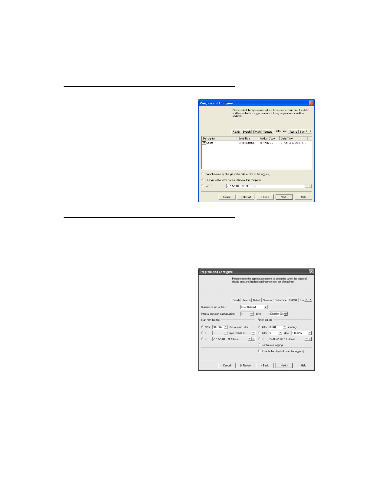
Date/Time Tab - Check that the date and time is correct.
If you have removed batteries from the iMiniPlus for
any length of time, make sure you either select:
Change to the date and time on this
computer (default)
Set to
The software will always default to the “Change to the
date and time on this computer.” option.
Setting the Start, Stop and logging duration
Startup Tab - Configure the start, recording and stop conditions.
The left-hand side of this tab displays the start conditions and the right-hand side the logging and stop
conditions
Duration of trip, at least
If you are using the iMiniPlus to record the temperature
of a trip (shipment) for instance, you have the option
of setting up the parameters yourself or let the
ConsolePro software calculate these automatically for
you.
The software takes the total memory available (8048
readings) and calculates the maximum interval
between each reading and the finish log trip time and
date based on the trip duration you select. You can
select 1day to 60day trip duration this way.
You will notice that each time you select a trip
duration, the logging interval will change.
Interval between each reading
This is sometimes called the logging interval or logging rate and is described as the period of time between
each logged reading. If the interval is a low number, then the iMiniPlus memory will be filled quickly
compared to a high number. If you want to record acute changes in temperature over short periods of time,
it is best to select a low number or faster logging interval. If you want a logger to record readings over a
long period of time, then you will be best advised to use a lower logging interval or high number.
The fastest logging interval the iMiniPlus can log at is every 5 seconds.
Page 32

30
MP D range MP Dry Ice
The slowest logging interval the iMiniPlus can log is every 18 hours.
Start new log trip
The only way to start an iMiniPlus is by using the START button. With other products it is possible to have
a timed or date start as well as a switch start.
You can also program a delay into the starting process of up to 4 hours 15 minutes. This will show
immediately after the Start button is pressed within the iMiniPlus LCD with the words “IN DELAY”. See
section
Starting and using the iMiniPlus
.
Finish log trip
There are several ways to cease a logging trip or period.
You can program the iMiniPlus to log until all the memory is used up (8048 readings) or you may wish to
log only 100 readings for instance.
Alternatively, you can select a certain number of days at which the iMiniPlus will stop logging. For instance
you may only want to record the temperature for a discrete period like a few days, after which you are not
interested in any further data recording.
At each time the iMiniPlus will stop logging and “STOPPED” will be displayed on the LCD
Continuous logging
If you are intending to place the iMiniPlus in an environment that you want to record temperatures 24/7
(for example, laboratory refrigerator), you can select the iMiniPlus to log continuously. This means that the
iMiniPlus will log until the memory it filled up at which time it will start overwriting the first logged data with
the latest.
Users must be careful to routinely download data from the iMiniPlus otherwise data may be lost. Careful
selection of the logging interval is required in this case.
It is possible to download at any time while the iMiniPlus is logging, without changing the program settings
.
Enable stop button in this logger(s)
The iMiniPlus Stop button can be activated through programming by simply ticking the appropriate box. See
section
Stopping the iMiniPlus.
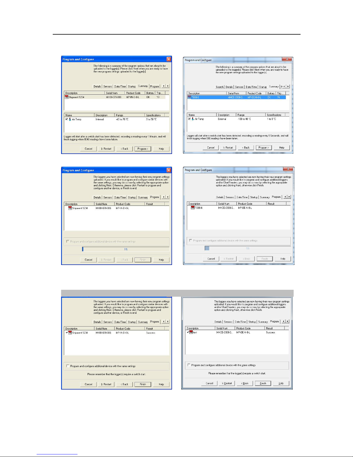
Summary and Upload Program into iMiniPlus
Once you have completed the programming, you will be given an opportunity to review all the conditions in
the Summary tab before you upload into the iMiniPlus. If you are not happy with them select the <BACK
button to return to the appropriate sections and amend.
Check that program settings are what you want.
Page 33
Preparing iMiniPlus for use 31
MP D range MP Dry Ice
Program conditions are being uploaded to iMiniPlus
The iMiniPlus has been correctly programmed
If the program settings have been uploaded correctly the blue progress bar will show 100% and the word
“Success” display in the Result field. There will also be a tick next to icon in the Description field. Select
Page 34
32
MP D range MP Dry Ice
the Finish button and when ready start the iMiniPlus and place in the environment to be recorded. See
section
Starting and using the iMiniPlus.
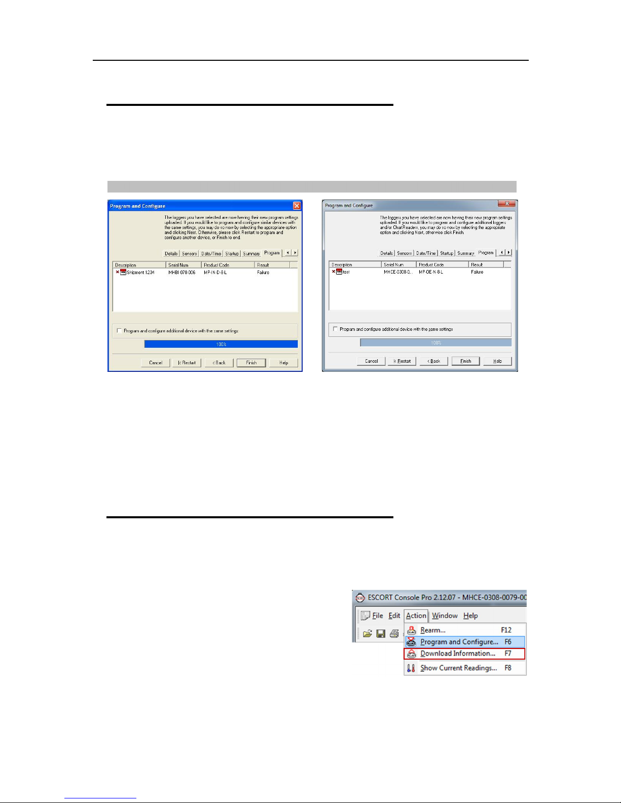
Program upload Failure
If the upload has failed either select the Cancel button to close the software and start again or select the
Restart button to start the sequence again. If the iMiniPlus still fails to upload, contact your local distributor
or Cryopak Verification Technologies
Program conditions have not been successfully uploaded into the iMiniPlus.
6. Results from iMiniPlus
The iMiniPlus stores the logged readings in its internal memory so you must use the ConsolePro software
to extract these readings through the USB or serial adaptor and into a format that can be displayed on the
PC screen. It is usually very important that the information retrieved from an iMiniPlus is retained. Through
the software you can save the information retrieved from an iMiniPlus to your disk drive so that you can
view the information at a later date. This chapter explains how you can retrieve the logged data stored
within an iMiniPlus and have the software display it to you on the screen in a meaningful way.
Getting results from iMiniPlus
Make sure the USB or serial cable is connected to your PC and to the iMiniPlus.
There are two ways to retrieve the data from an iMiniPlus, both of which will achieve the same result.
Click the Download Information icon on the toolbar
Click the "Download Information..." item located under the
Action menu.
The process of retrieving data stored within an iMiniPlus
does not erase it from the memory. If the iMiniPlus is
currently recording while you retrieve the information, it will
continue to record without interruption.
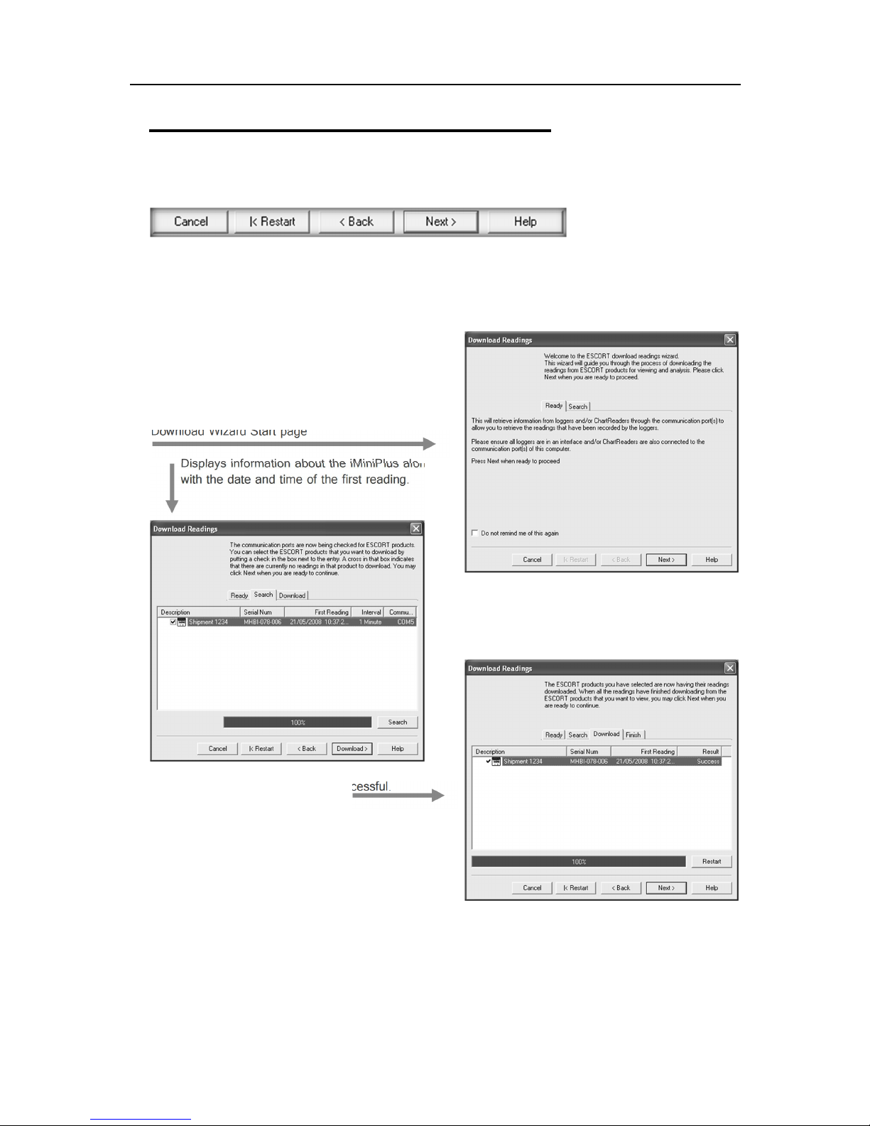
The Download Information feature initiates the Download
Wizard.
Page 35
Results from iMiniPlus 33
Displays information about the iMiniPlus along
‘Download’
Download Wizard
During the progress of the Download Wizard, you will see a series of 5 buttons at the bottom of the wizard
box.
The “Cancel” button immediately stops and closes the wizard. To start again you will have to select the
Download icon. The “Restart” button enables you to start the Wizard progress from the beginning without
closing the feature. “Back” enables you to go back one step in the step-by- step progress and “Next” takes
you to the next step. The Next button is preceded by the “Download” button. The Help button will provide
description and instruction about the step you are in. Please note that this feature may make reference to
other products from time to time. Additionally some
Help documentation may not be present due to the
software version you are currently using. Consult this
iMiniPlus manual if you are not sure about any
description.
Download Wizard Start page
Displays information about the iMiniPlus along
with the date and time of the first reading.
Indicates that the Download was successful.
with the date and time of the first reading. Click
Page 36
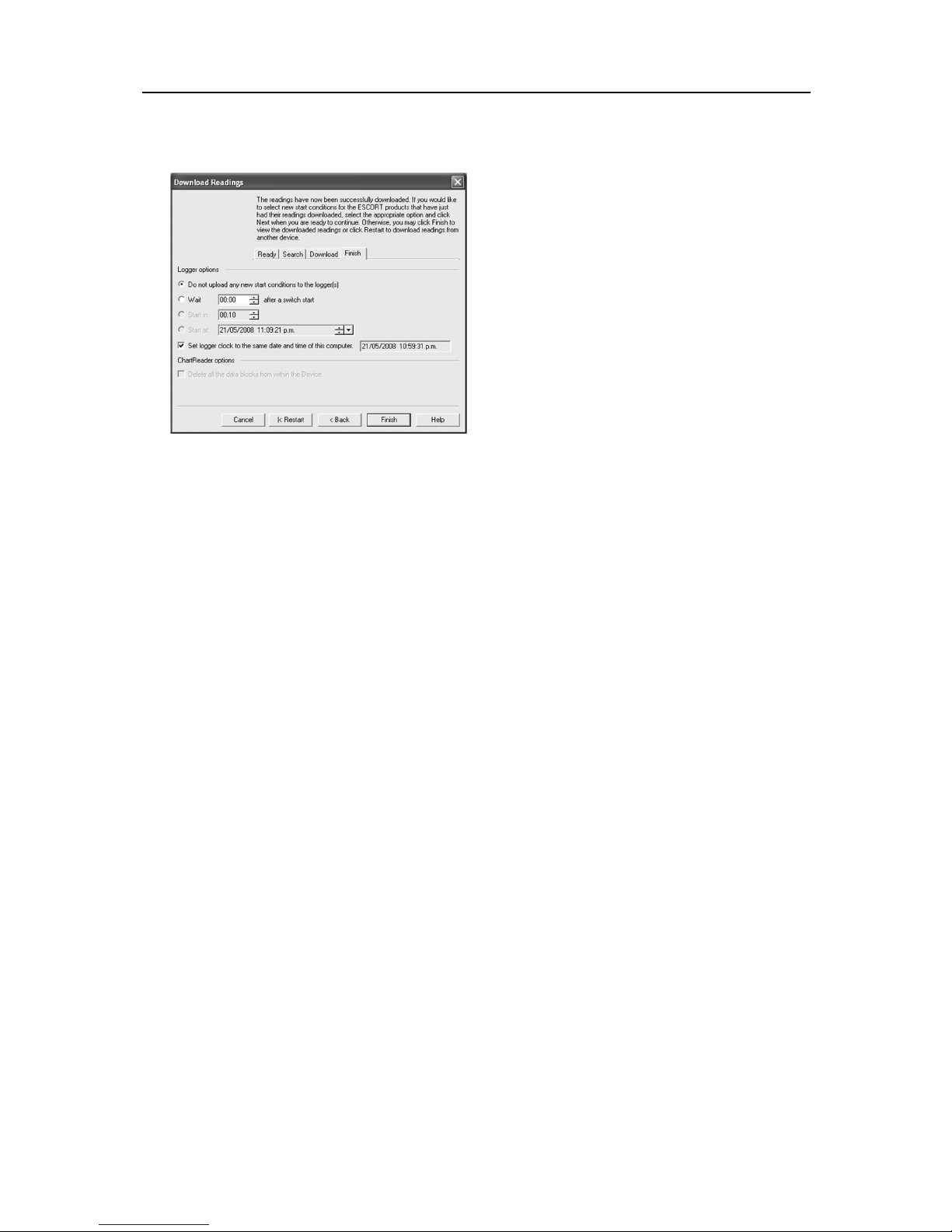
34
If FAILURE appears in the Result and there is a RED X next to in the Description this may indicate the
iMiniPlus has already been programmed. If this is not the case, there is a fault with the iMiniPlus and it will
need to be returned to your distributor.
You have the option of programming the new start
conditions. This may be help for instance when you
are having to reset a large number of iMiniPlus
loggers for a new application. Otherwise leave
Logger option at default setting “Do not upload any
new start conditions to the logger(s)”
Page 37

Results from iMiniPlus 35
Inspecting the information at close range
When a file is displayed either from downloading or from calling up a stored data file, the file first appears
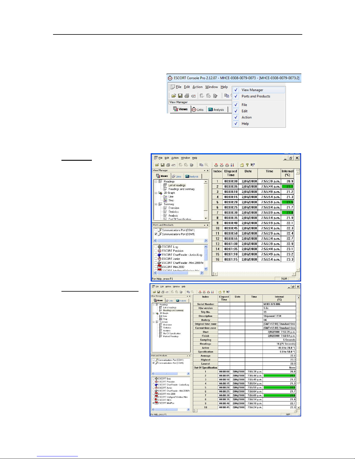
as a list of readings. It might look something like this:
View Manager
The View Manager is a useful data viewing tool and by default, occupies the left side of the ConsolePro
window. The View Manager will only be functional when a set of data has been opened or been
downloaded from an iMiniPlus.
If you want to see the View Manager in any other ConsolePro window location, simply select and drag. The
View Manager has 3 tabs:
1. Views - Manages the type of reading, graph or summary you would like to display.
Page 38
36
2. Links - Manages which data you would like to analyze or compare.
3. Analysis - Manages which type of analysis you would like to add in the displayed readings or graphs.
To hide or display the View Manager,
choose
Options
or deselect
option from the
you can right click on the menu or toolbar
area to select the View Manager. As shown:
from the
Edit
menu. Select
Display the View Manager
General
tab. Alternatively
Views
The Views window has 3 top-level headings. To expand or collapse the content of any headings just left
click on it. Each heading contains a drop down list of further items. To display the item double-click on the
item you would like to see.
Readings
List of readings - displays a table
with separate line for each reading
taken. Each line shows the date and
time the reading was made and the
measurement made by each sensor.
Readings and summary
Displays reading summary report
followed by detailed list of actual
readings. Summary report includes
such facts as the serial number of
the iMiniPlus and a description of the
environment recorded, trip number,
start and finish dates, time zone,
number of readings, etc.
Page 39
Results from iMiniPlus 37
Overview - displays overview information
Statistics - displays the serial number, the
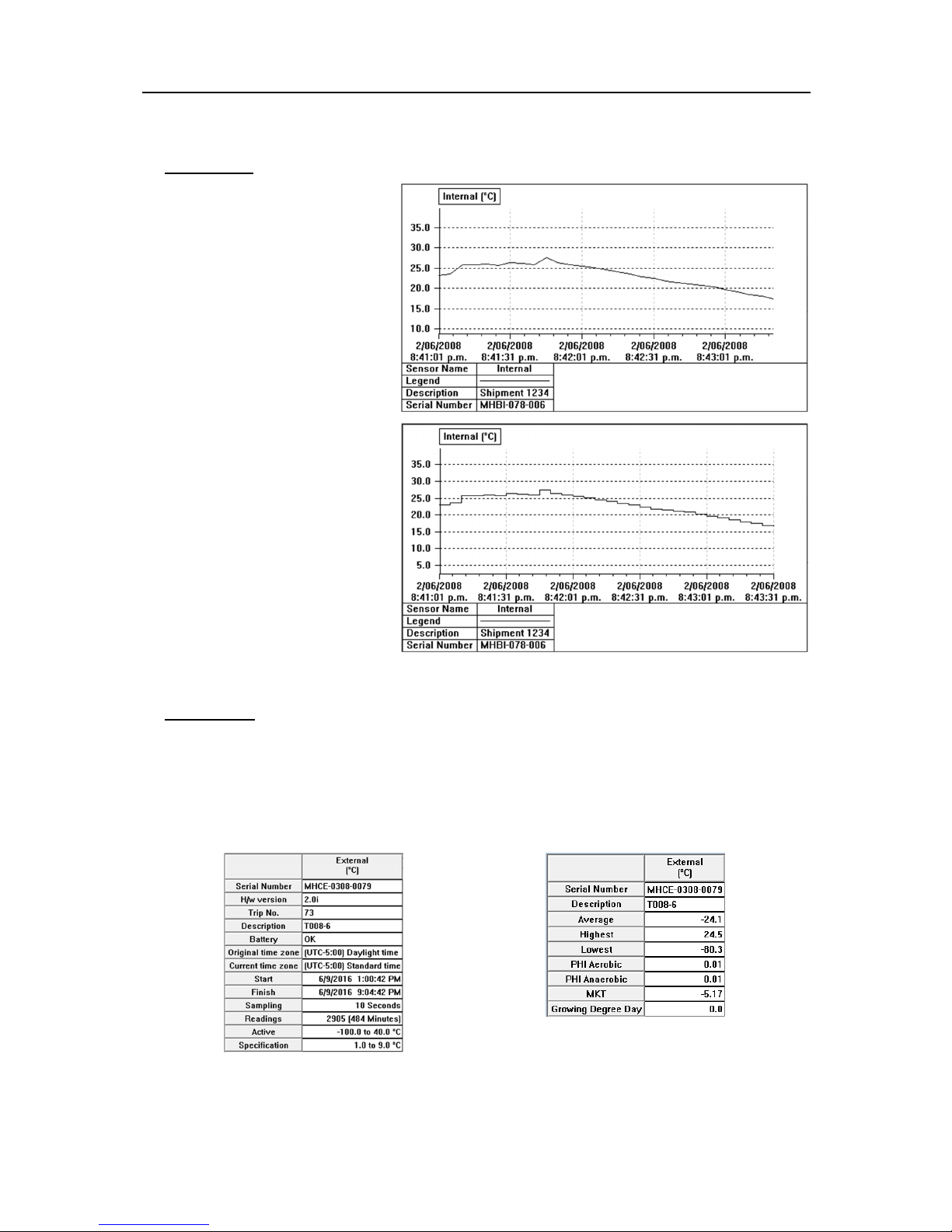
2D Graph.
Line - displays the logger’s reading
as a line graph.
Step - displays the logger’s readings
as a step graph.
You can enlarge a section of the
graph with the mouse. Move the
mouse to one corner of the area you
want to zoom, press the left mouse
button, drag the mouse to the
opposite corner, and release the
button to enlarge a section of the
graph. Press the toolbar zoom button
or right click the mouse to restore
(un-zoom) the graph.
Summary.
of the current logger such as serial
number, trip number, battery report, time
zone, start and finish dates, number of
readings, readings interval, logger’s
range and specification.
description, the highest and the lowest value
of readings, the average value of readings,
the Process Hygiene Index (PHI), Mean
Kinetic Temperature (MKT), a Custom value
and Grower Degree Day (GDD).
Page 40
38
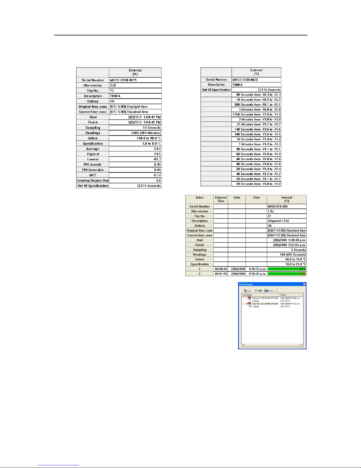
Analysis – displays a summary report
Out-of-Specification – displays a
readings.
and includes previous parameters.
Marked Readings – displays the bookmarked
readings.
breakdown of the out of specification
Links
The Links window provides a way to analyze and/or compare data from
multiple iMiniPlus loggers, which could have been logged over different
time periods and/or different logging intervals.
Simply download the iMiniPlus loggers you are interested in comparing.
The data may also be from previous logged period on the same iMiniPlus.
For download instructions see the section
window you can see all the iMiniPlus loggers or data that ConsolePro has currently open and displayed.
Simply select the iMiniPlus and its sensor to include it into the current display window. Note that
ConsolePro shows the
automatically selected when the parent box is selected. It refers to the sensor description of the iMiniPlus
model MP-IN-D-8-L in which the sensor is housed internal to the iMiniPlus body. The word
be show in the model MP-OE-D-8-L and it refers to the sensor that is externally connected to the
iMiniPlus via a one meter cable.
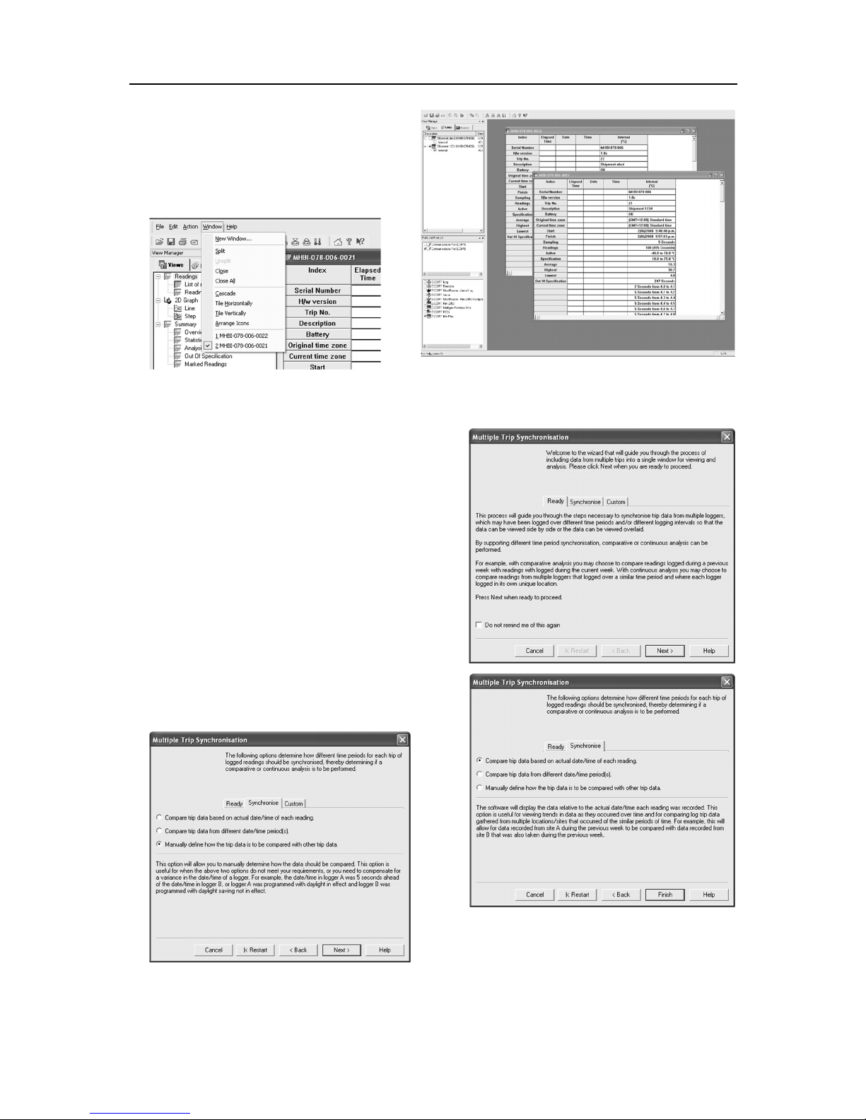
Each time an iMiniPlus is downloaded into ConsolePro software or a series of data is opened, a separate
Readings and Summary box is opened like the picture below:
“Internal”
under the description and serial number of the iMiniPlus. This is
“Download Wizard”.
In the Links
“External”
will
Page 41
Results from iMiniPlus 39
Each iMiniPlus dataset can be maximized into
the ConsolePro window and then be selected
through the
Window menu
as below:
Multiple Trip Synchronization Wizard
When more than one set of data appears in the Links
window and is selected with a tick, the
Synchronization Wizard
through the process of including the data from the other
iMiniPlus into the current display.
To compare log trip data gathered from multiple
locations at similar periods of time, it is recommended
that you select the option
will start and guide you
“Compare trip data based on
actual date/time of each reading”
will allow data recorded from one site to be compared
with data from another during the same interval of time.
To compare log trip data gathered from multiple and/or
the same location during different periods of time, it is
recommended that you select the
data from different date/time period(s)
for comparing current log data with that of a previous
week.
Multiple Trip
. For example, this
option “Compare trip
”. This is useful
To customize how the log trip data from an iMiniPlus is included, select the option
the trip data is to be compared with other trip data”
“Manually define how
.
Page 42
40
av
the calculated arithmetic mean
n
the number of data points to include in the calculation
ti
a data point to include in the calculation
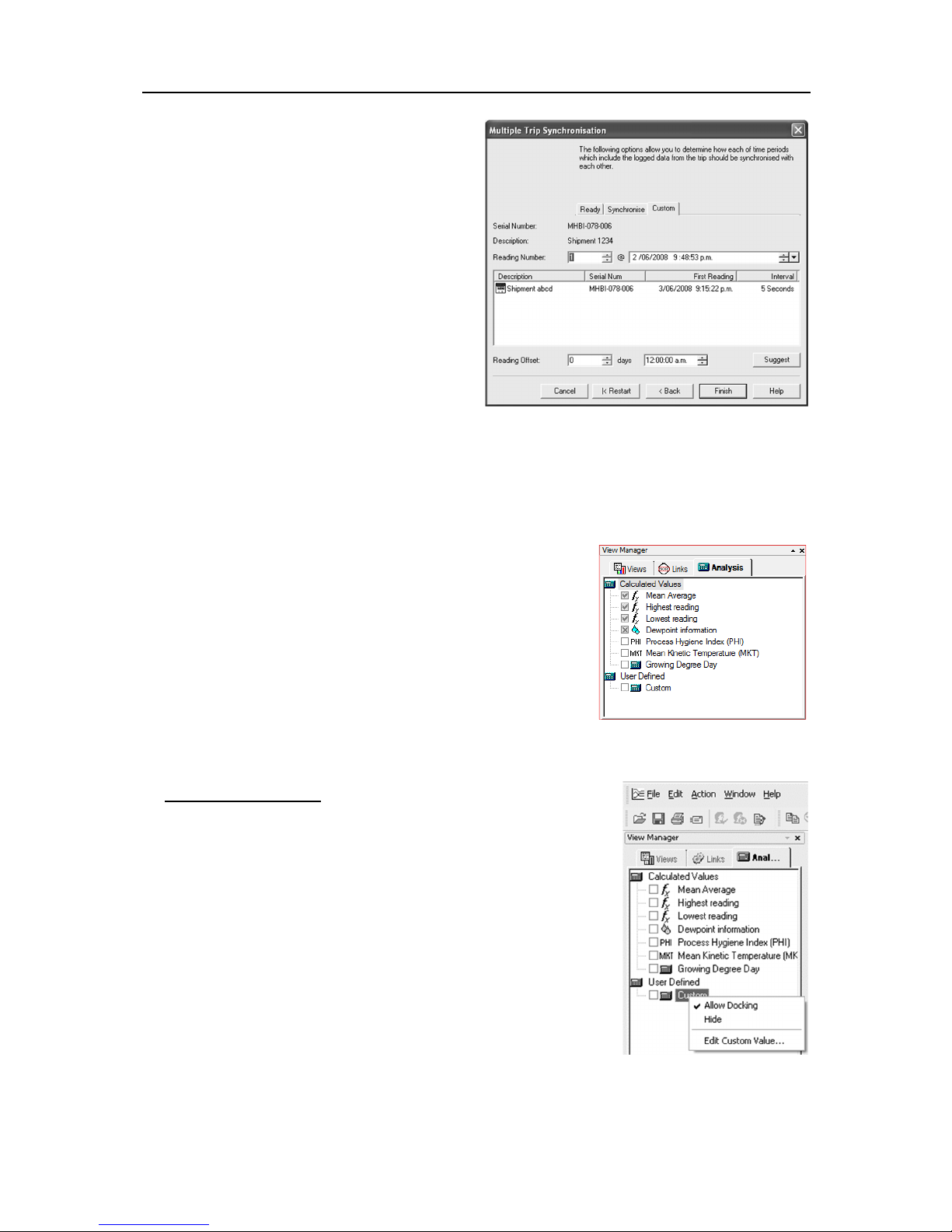
This step provides you with a screen that will allow
you to manually adjust the alignment offset through
the Reading Offset controls.
Serial Number displays the serial number of
the iMiniPlus to be added to the current view.
Description displays the description of the
iMiniPlus to be added to the current view.
Reading Number shows the reading number,
the iMiniPlus has/would have taken at the
date/time specified in @ field.
Reading Offset allows you to adjust first
reading time of the currently displayed
iMiniPlus to synchronize it with first reading
time of the iMiniPlus that is going to be added
to the current view.
You can use Reading number or @ fields to set
time and date to be used for the first reading of the iMiniPlus to be added or you can use Suggest button
to allow software set first reading date and time.
Also you can see details of the currently displayed iMiniPlus: description, serial number, date and time of
the first reading, interval between readings.
Analysis
When a file is displayed either from downloading or from calling up a
stored data file, the software will automatically calculate and display
some statistics of the recorded data. These statistics can be displayed
in the Readings, 2D Graph and Summary features of the View tab.
When choosing a 2D Graph view, these statistics can be optionally
displayed in the graph window.
The Analysis window has 2 top-level headings. To expand or
collapse the content of any headings just click on it. Additionally if you
right click on the Values or User Defined statistics, you will be able to
edit and/or view reference material. See right image below:
Calculated Values
Mean Average
Select this option to display the average value of readings in the 2D graph
legend.
The Mean Average reading is the arithmetic mean of the sequence of
data points. It is calculated by adding all the data point values together
and then dividing the total by the number of data points. Mathematically
this formula can be expressed as illustrated in the following picture:
Where:
For example, if there were 5 data points to calculate the arithmetic mean of and they were, 12.3, 15.9,
16.2, 14.7, 14.9, then the arithmetic mean would be 14.8.
Page 43
Results from iMiniPlus 41
Highest reading
Select this option to display the maximum value of the iMiniPlus readings in the 2D graph legend.
Lowest reading
Select this option to display the minimum value of the iMiniPlus readings in the 2D graph legend.
Dewpoint information
This statistic is not available on the iMiniPlus. (Relative Humidity loggers only)
Process Hygiene Index (PHI)
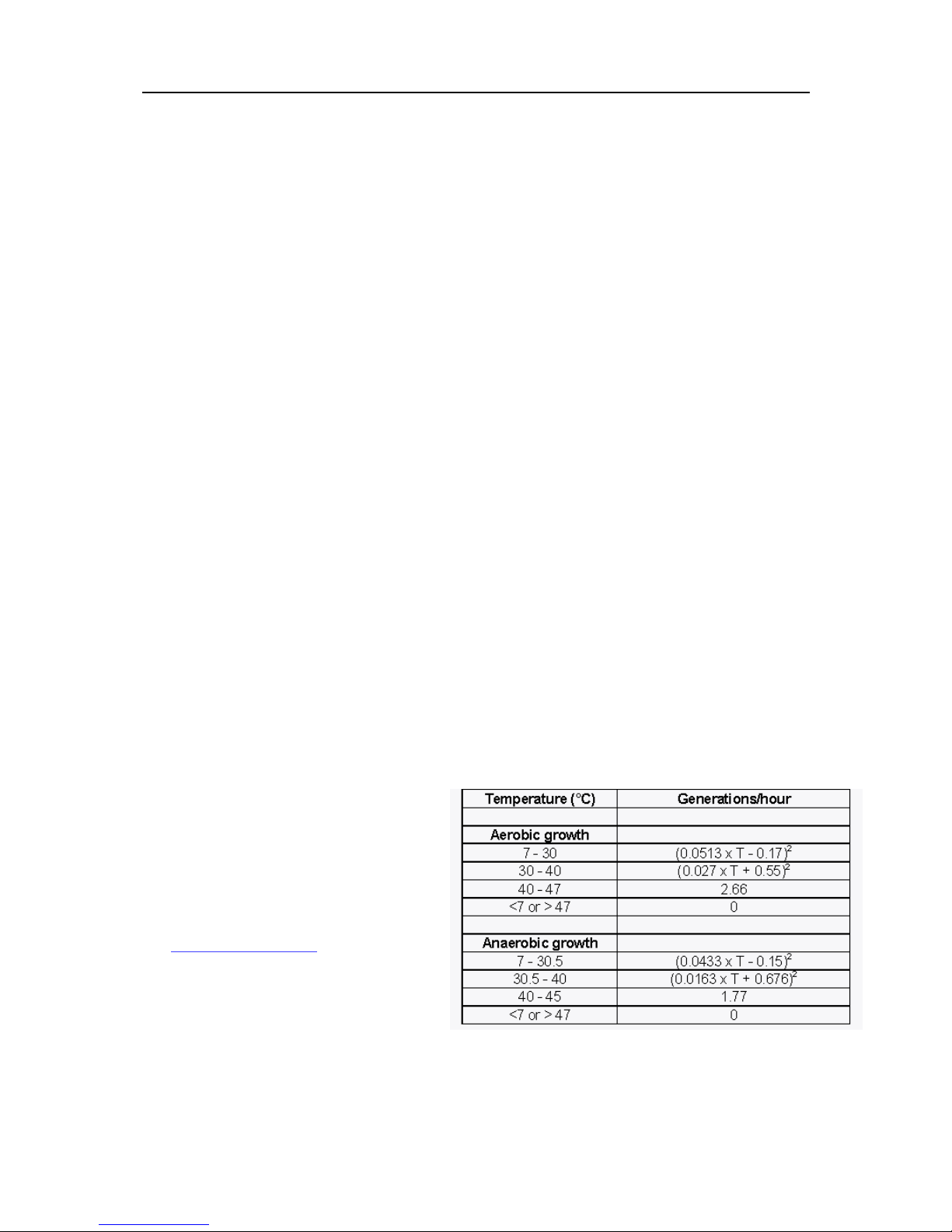
Select this option to display the aerobic and anaerobic process hygiene index of iMiniPlus readings in the
2D graph legend.
Process Hygiene Index (PHI) is:
a unit of potential microbial growth equivalent to one generation of Escherichia coli ;
an approximation of the amount of potential bacterial growth during the cooling process of meat
products from slaughter until the meat has cooled to 7°C (44.6°F) or less;
a way of evaluating the overall hygiene of the meat cooling process.
Process Hygiene Index (PHI) consists of:
Aerobic growth (growth on the outer layer of the meat carcass) of Escherichia coli during the cooling
process;
Anaerobic growth (growth internal to the meat carcass) of Escherichia coli during the cooling process;
the temperature of the meat during the cooling process.
The Process Hygiene Index (PHI) standard:
The MAF (New Zealand) Industry Standard
6 indicates that PHI values should not
exceed a maximum of 14, and a mean of 7.
For more detailed information on the
application and use of PHI calculations, refer
to New Zealand Ministry of Agriculture and
Forestry (MAF) Industry Standard 6,
Processing of Edible Product, which is
available through the Internet site
(
http://www.maf.govt.nz
Software calculates Process Hygiene Index
(PHI) using the following formulas:
)
T is the temperature in °C.
Mean Kinetic Temperature (MKT)
Page 44
42
15
24.48
24.17
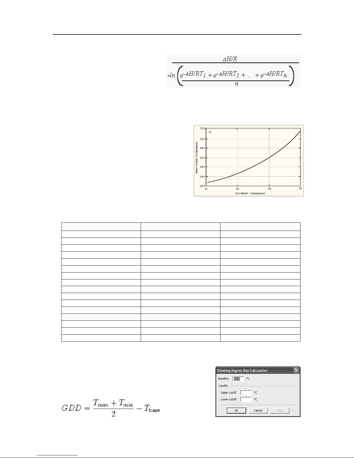
Select this option to display the Mean Kinetic Temperature of the iMiniPlus readings in the 2D graph legend.
There are some products and materials that
exist which have accelerated rates of
degradation at higher temperatures. For
example, perishable food items,
pharmaceutical products and many forms of
bacteria can grow/degrade exponentially as
the environmental temperature increases.
Mean kinetic temperature is a calculation that accommodates the non-linear thermal effect temperature can
have on products. Mean kinetic temperature is represented as the equivalent temperature the product was
thermally subjected to during the period of time the
various temperature readings were recorded. As an
illustration of how the MKT calculation will affect an
expressed mean for a yearly calculation (important for
the long term storage of critical drugs and chemicals),
here is an illustration:
If the temperature is constant for an entire year, but is
"off" for a single month of that year, there will be a
difference in the calculated arithmetic mean (the sum of
all of the measurements divided by the number of
measurements--a simple mean) and the kinetic mean.
The following graph and table show the differences which
are calculated by both methods:
Effect on Kinetic and Arithmetic Mean Temperatures on storage for one month at other than 25° C.
Temperature (one month) Mean Temp.(Kinetic) Mean Temp.(Arithmetic)
16 24.51 24.25
17 24.54 24.33
18 24.58 24.42
19 24.62 24.50
20 24.67 24.58
21 24.72 24.67
22 24.78 24.75
23 24.85 24.83
24 24.92 24.92
25 25.00 25.00
26 25.09 25.08
27 25.18 25.17
28 25.29 25.25
29 25.41 25.33
30 25.53 25.42
Although the effect is not dramatic, it is clear that the MKT method weights the higher temperatures in a
series more than the lower temperatures.
Growing Degree Day
GDD are calculated by taking the average of the daily maximum
and minimum temperatures compared to a base temperature,
(usually 10 °C). As an equation:
T
,
base
Page 45
Results from iMiniPlus 43
Symbol
What it means
+
addition
-
subtraction
*
multiplication
/
division
^
raise to power
(
left bracket
)
right bracket
sqrt( )
square root
exp( )
exponential
log( )
natural logarithm
log10( )
base 10 logarithm
abs( )
absolute value
$
where to put sensor value into the formula
GDDs are typically measured from the winter low. Any temperature below
T
base
is set to
T
base
before
calculating the average. Likewise, the maximum temperature is usually capped at 30 °C because most
plants and insects do not grow any faster above that temperature. However, some warm temperate and
tropical plants do have significant requirements for days above 30 °C to mature fruit or seeds.
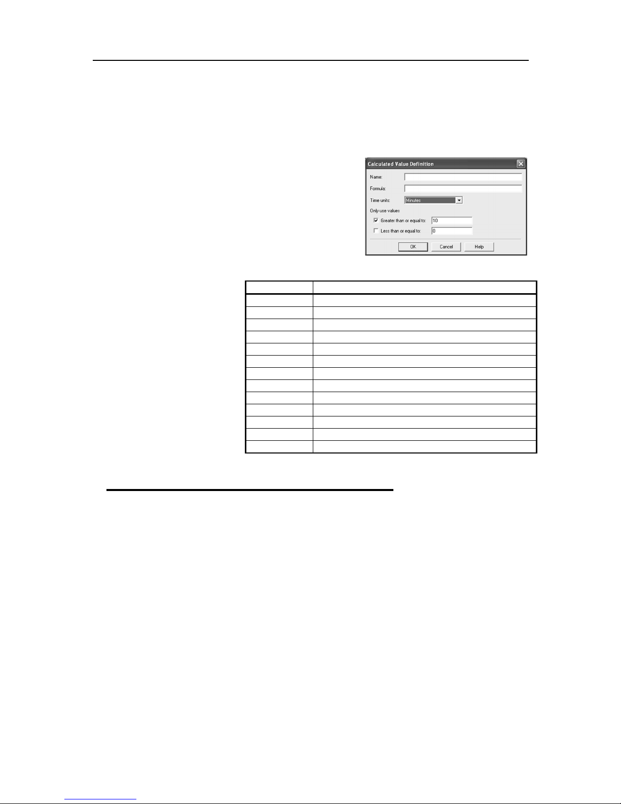
Custom Value
Select this option to display custom defined value of readings in
the graph’s Legend. Double clicking on the Custom item opens
the Calculated Value Definition dialog box.
Name
- any name you wish. For example, ‘’Calculated fresh
value of food’’.
Formula
- enter the formula used to convert each sensor’s
reading into the calculated
value.
Example:
The value of fresh food is given
as:
Fresh Value = (Measured
Temperature - Target
Temperature) * Time
Assume the Target Temperature
is 60°C.
Set the Formula to $ - 60.
Set the Time Units to hours.
Select Greater than or equal to
option and set limit to 60.
The mathematical operations
currently supported include:
View Data in a Graph
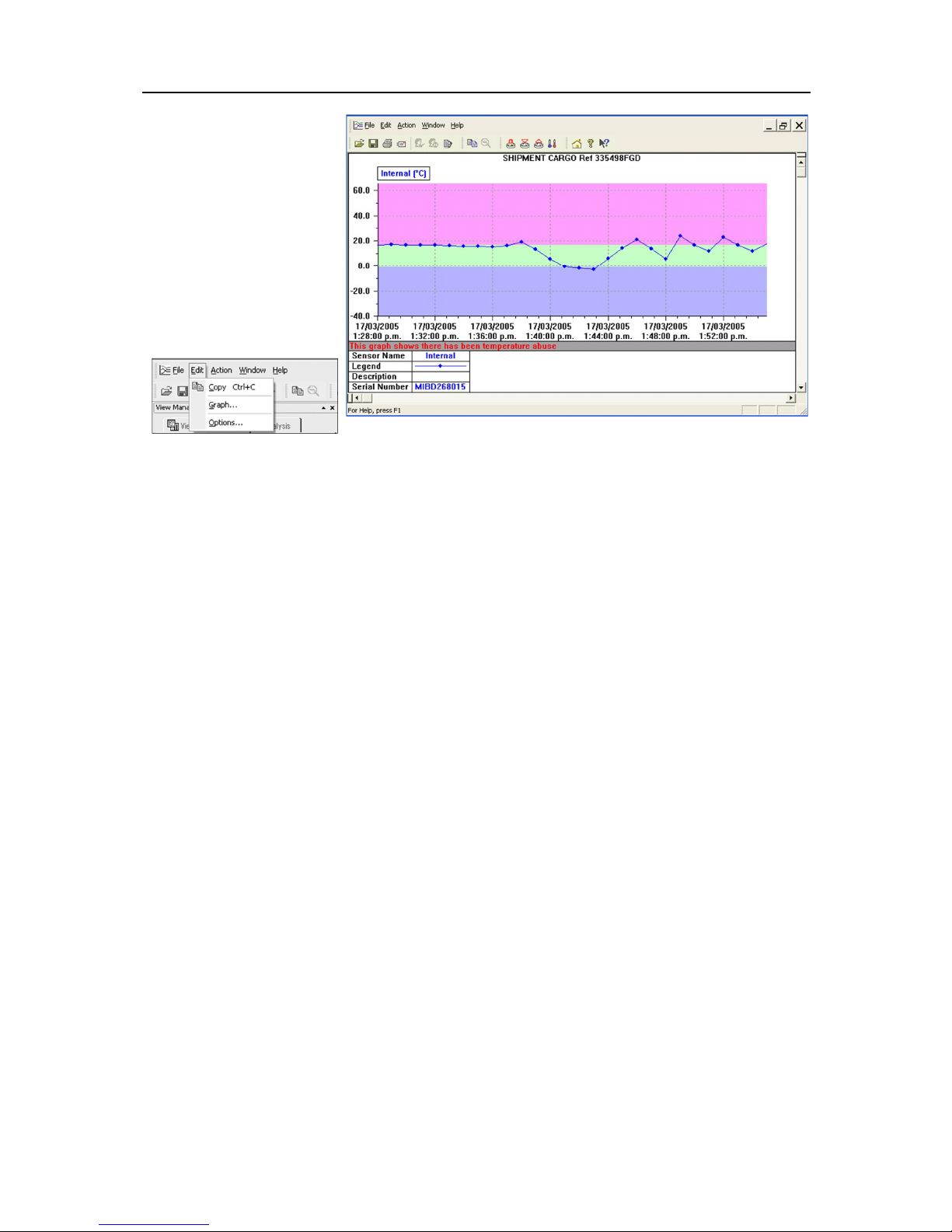
Open the data either from downloading an iMiniPlus or from a saved file. When the data opens it will
present a List and Summary Report. Go to the View Manager and select the View tab. Then select 2D
graph either Line or Step. The graph will presented like below:
Page 46
44
You can select the Graph
option under the Edit menu
to customize the look of the
2D graph.
Page 47
Results from iMiniPlus 45
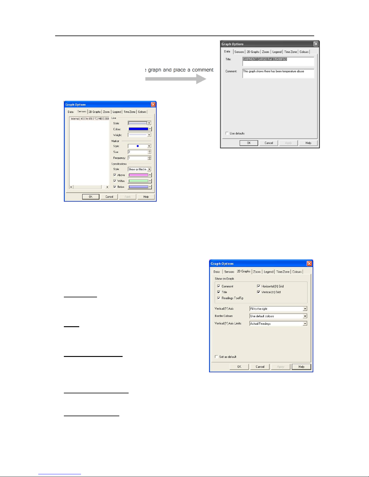
Data
You can add a title to the top of the graph and place a comment
below.
Sensors
In the Sensors tab you can customize the look of the graph with various line and color styles. You can
color the graph to show the alarm (specification) limits as shown in this example.
In the left hand side of the box the description of the iMiniPlus data is displayed. If there were more than
one data file was selected through the Multi Trip Synchronization feature, you would see those listed here
as well.
By selecting each sensor description, you can customize how each is displayed on the Multi Link graph.
See Multiple Trip Synchronization Wizard section
2D Graphs
Comment
Select this box if you want to display the comment line on
the bottom of the graph
Title
Select this box if you want to place a title on the top of the
graph.
Readings ToolTip
Select this box if you want the Tooltip box to open next to
the mouse cursor on the graph. The box will show the date,
time and reading at any point along the x-axis.
Horizontal (X) Grid
Select this box if you want to display a dashed horizontal grid on the graph.
Vertical (Y) Grid
Select this box if you want to display a dashed vertical grid on the graph.
Page 48
46
Vertical (Y) Axis
This enables you to fill the graph from the left or right or use both sides of the graph.
Border Colors
This enables you to select border colors for your graph.
Vertical (Y) Axis Limits
This enables you to display the graph Y-axis (temperature readings) to fit either the complete range of the
sensor (-40°C to +70°C) or within the alarm limits (if programmed) or from 0°C to the actual readings.
Select the Apply button to update the 2D graph.
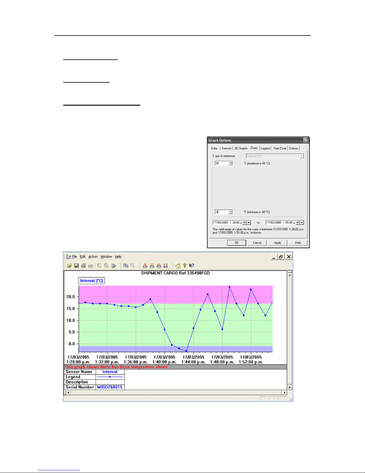
Zoom
The Zoom feature allows you to manually adjust the
temperature and time co-ordinates to select certain areas of
interest. In this example +30°C and -4°C have been
selected.
Page 49
Results from iMiniPlus 47
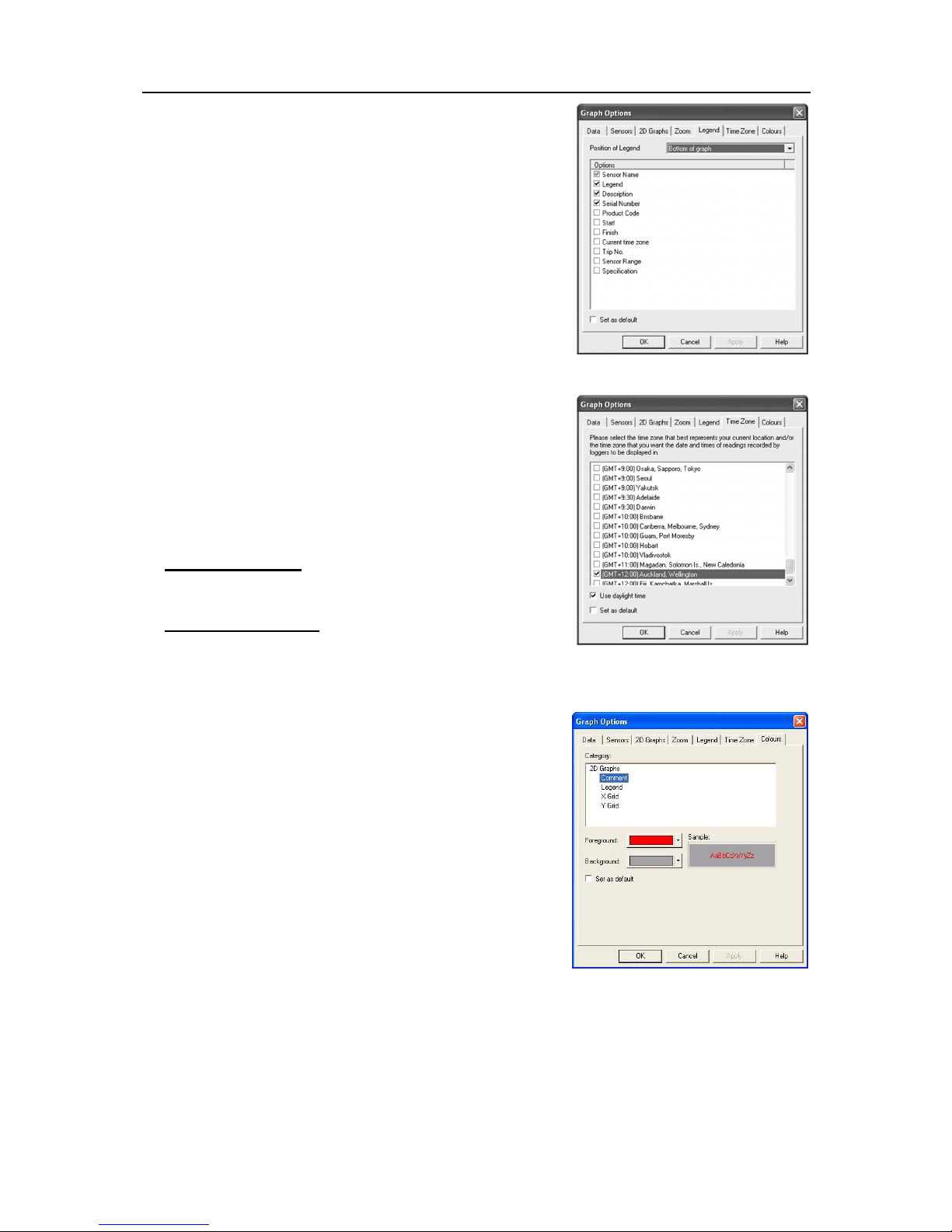
Legend
The legend can be positioned at the top, bottom, left and right of
the graph, or omitted altogether. As well as the above Legend
options, the various Calculated values and/or Custom value can
be displayed. See Analysis in the View Manager section. These
values can be selected or deselected from the Manager while the
2D graph is displayed.
Time Zone
In some cases, the configuration time zone will be different from
the time zone at the download location. This allows you to select
which time zone will be used to display dates and times within the
graph and data displays. This option will not have any effect on
the original recorded data.
GMT Time Zone
All times are displayed in Greenwich Mean Time representation
Use daylight time
By selecting the box, the iMiniPlus data will shift +1 hour to
accommodate Daylight Saving Time.
Colors
2D Graphs can be customized to your color preferences.
Page 50
48
Printing the results
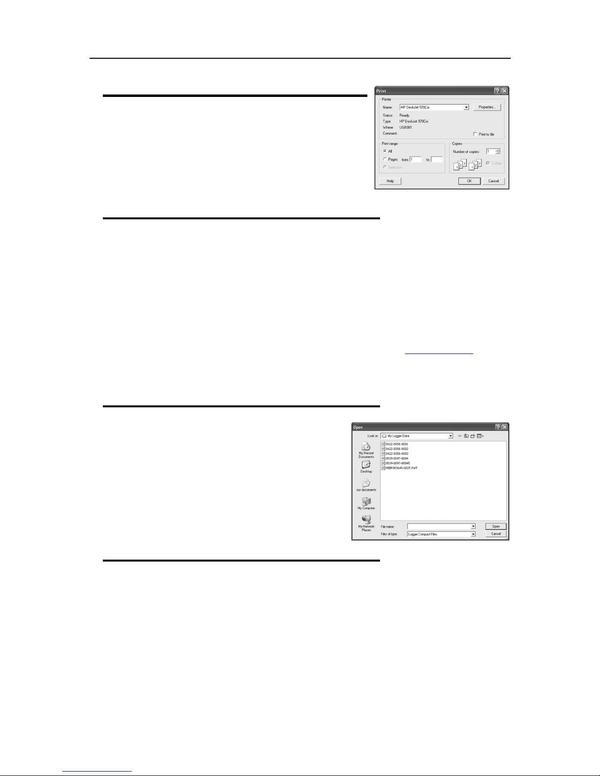
The print window can be brought up by simply clicking once on the
"Print" icon located on the
toolbar
or by clicking the "Print..." menu
item from within the File menu.
Sending a file by e-mail direct from Console
You can send files of interest to another person, by e-mail, directly from the software without the need to
exit to your e-mail software or to deal with file attachments.
While you have the file of interest open and being displayed on the screen, just click once on the "Send
Mail" icon located on the
attachment. Type the desired e-mail address to send the file of interest to, add any message that you wish
to include, and then click "Send".
Clicking the "Send..." menu item within the File menu will achieve the same results as clicking the "Send
Mail" icon as previously described.
Note, the recipient of the file will also need to have a copy of the ConsolePro software to open and view
the file that you sent. ConsolePro software is free and can be downloaded from www.cryopak.com
If you want to attach your data files in file formats other than the ConsolePro format, save the desired file
formats in
Save As
toolbar
section of the
and your e-mail software will pop up with the file already inserted as an
File
menu, and attach to an email through the email software.
Calling up previous results
The files that have most recently opened and displayed are
listed towards the bottom of the "
files, click the "Open" icon located on the
File
" menu. To open other
toolbar
, which will
display the "Open" file dialog similar to the following picture
and allows the user to locate and open one or more files of
interest.
Clicking the "Open..." menu item within the File menu will
achieve the same results as clicking the "Open" icon as
previously described
.
Digital signatures
Support for digital signatures is primarily provided for compliance with the US FDA 21 CFR Part 11
regulation - Electronic records and electronic signatures. Various industries however, may find inclusion of
digital signatures beneficial towards their quality control and assurance systems.
Digital signatures allow users to include their digital signature within an ConsolePro file along with a
meaning/reason for the inclusion of the digital signature. To add digital signatures to ConsolePro files, a
licensed copy of User Admin software must also be installed. For more information about how to use User
Admin software contact your distributor.
7. Customizing the software
Page 51
Customizing the software 49
General
Advanced
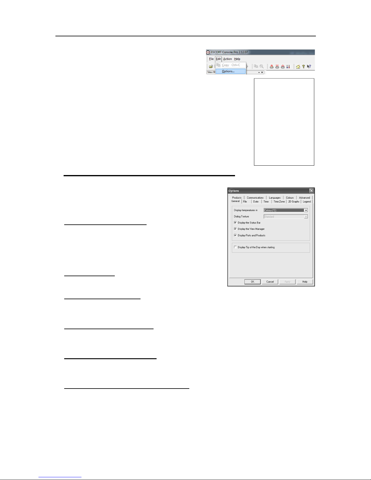
In the "Edit" menu is a command called "Options..."
This menu command opens a Window, which will allow the
many of the features that the software offers to be customized. The following
sections will provide an explanation of each of these options so that users will
be able to make the best use of the software. The options that are available
for customization are grouped together into the following sections:
Nearly All of the options available will change the software in real time. For
example, if the language selection and/or the date format are changed, all
windows that are open will be updated without the need to restart the software.
If you make a change which does require ConsolePro to be restarted, you are
informed by an on screen message.
All these options are stored on a per user basis. Therefore, if more than one
user operates on a single workstation the software will allow different
customization settings for each.
File
Date
Time
Time Zone
2D Graphs
Legend
Products
Communications
Languages
Colors
General
The General Settings options allow you to change various
preferences that will affect the overall appearance of the information
shown by the software.
Display temperatures in
This will determine what units of measurement temperatures will be
displayed in. The options include:
Fahrenheit (°F)
Celsius (°C)
Kelvin (K)
Dialog Texture
The feature is disabled
Display the Status Bar
Select this box to display the Status bar and the bottom of the software screen. See Chapter 8 Menus and
Toolbar.
Display the View Manager
Select this box to display the View Manager in the left hand side of the screen. See section called View
Manager.
Display Ports and Products
Select this box to display the available communications ports and list of loggers that need to be selected.
See section Getting an iMiniPlus ready for logging.
Display Tip of the Day when starting
Select this box if you want to display a Tip of the Day box when ConsolePro is first opened. This can be
particularly useful for new users of ConsolePro software.
Page 52
50
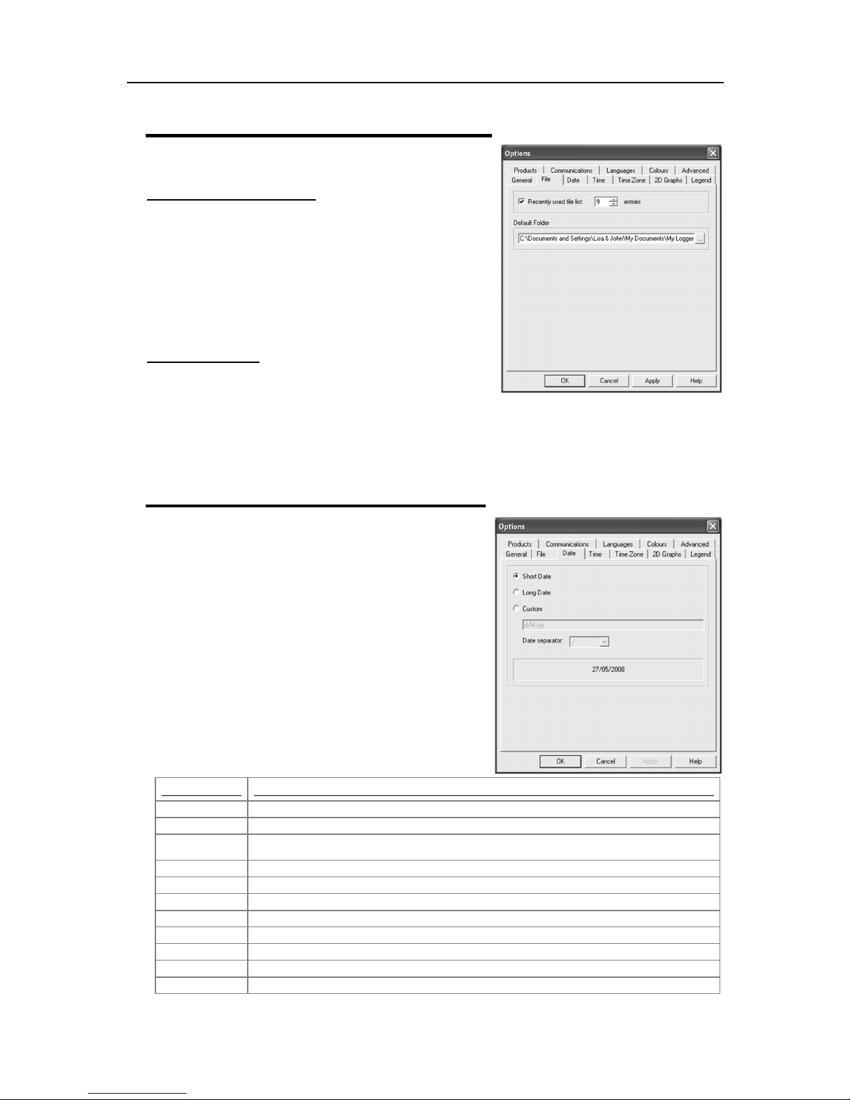
Element
Meaning
d
Day of month as digits with no leading zero for single-digit days.
dd
Day of month as digits with leading zero for single-digit days.
ddd
Day of week as a three-letter abbreviation.
dddd
Day of week as its full name.
M
Month as digits with no leading zero for single-digit months.
MM
Month as digits with leading zero for single-digit months.
MMM
Month as a three-letter abbreviation.
MMMM
Month as its full name.
y
Year as last two digits, but with no leading zero for years less than 10.
yy
Year as last two digits, but with leading zero for years less than 10.
yyyy
Year represented by full four digits.
File
Recently used file list
This determines how many of the most recently accessed files
are listed in the "
viewed again. Once this number of files has been reached, the
reference to the oldest file opened will be removed and the
most recently opened file will be added to position 1. Only the
file reference is removed from this list, the actual file is not
deleted. Changing this setting will take effect the next time
ConsolePro is started.
File
" menu for quick access to be opened and
Default Folder
This determines the location where the files are stored. The
location defined here can specify a local drive path or a network
drive path. UNC folder names are supported. The button at the end of the edit control will assist you to
locate the default store folder by browsing the folder structure available to you, if you choose to use it.
Since this is the default location where files are stored, this also represents the default folder that will be
used when searching for files to open (through the Open command in the File menu). The default location
is “..\My Documents\My Logger Data”.
Date
The Date setting allows how the date information can be
displayed by the ConsolePro software. It does not affect how
the date information is stored and therefore, how the date
information is shown can be changed at any time. Within this
option window, a sample of the date using the formats
selected will be displayed.
To customize how the date information is displayed, the
following elements may be used. If spaces are used to
separate the elements, these spaces will appear in the same
location in the date displayed. The letters must be in
uppercase or lowercase as shown in the following table (for
example, "MM" not "mm"). Characters that are enclosed in
single quotation marks will appear in the same location and
unchanged in the date displayed.
Page 53
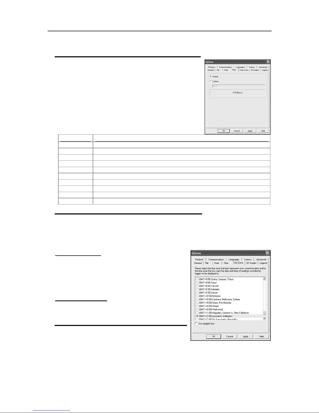
Customizing the software 51
Element
Meaning
h
Hours with no leading zero for single-digit hours; 12-hour clock.
hh
Hours with leading zero for single-digit hours; 12-hour clock.
H
Hours with no leading zero for single-digit hours; 24-hour clock.
HH
Hours with leading zero for single-digit hours; 24-hour clock.
m
Minutes with no leading zero for single-digit minutes.
mm
Minutes with leading zero for single-digit minutes.
s
Seconds with no leading zero for single-digit seconds.
ss
Seconds with leading zero for single-digit seconds.
t
One character time-marker string, such as A or P.
tt
Multi character time-marker string, such as AM or PM.
Time
To customize how the time information is displayed, the following
elements may be used. If spaces are used to separate the elements,
these spaces will appear in the same location in the time displayed. The
letters must be in uppercase or lowercase as shown in the following
table (for example, "ss", not "SS"). Characters that are enclosed in
single quotation marks will appear in the same location and unchanged
in the time displayed.
Time zones
In some cases, the configuration time zone will be different from the time zone at the download location.
This allows you to select which time zone will be used to display dates and times within the graph and data
displays. This option will not have any effect on the original recorded data.
GMT Time Zone
All times are displayed in Greenwich Mean Time representation
Use daylight time
By selecting the box, the iMiniPlus data will shift +1 hour to
accommodate Daylight Saving Time.
2D Graphs
Page 54
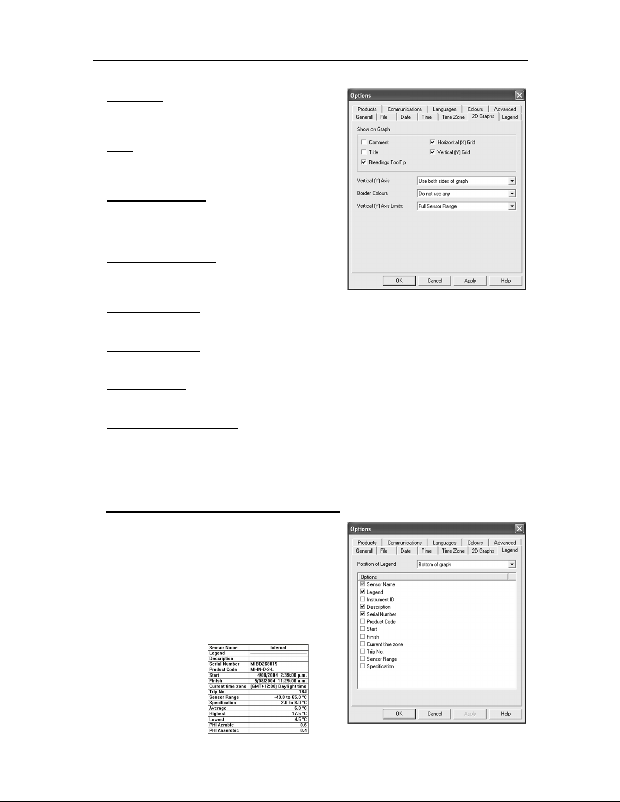
52
Comment
Select this box if you want to display the comment line on
the bottom of the graph
Title
Select this box if you want to place a title on the top of the
graph.
Readings ToolTip
Select this box if you want the Tooltip box to open next to
the mouse cursor on the graph. The box will show the
date, time and reading at any point along the x-axis.
Horizontal (X) Grid
Select this box if you want to display a dashed horizontal
grid on the graph.
Vertical (Y) Grid
Select this box if you want to display a dashed vertical grid on the graph.
Vertical (Y) Axis
This enables you to fill the graph from the left or right or use both sides of the graph.
Border Colors
This enables you to select border colors for your graph.
Vertical (Y) Axis Limits
This enables you to display the graph Y-axis (temperature readings) to fit either the complete range of the
sensor (-40°C to +70°C) or within the alarm limits (if programmed) or from 0°C to the actual readings.
Select the
For more information about how to create and customize graphs, see section
Legend
Each graph generated has a legend that information can
be added to.
The legend can be positioned at the top, bottom, left and
right of the graph. Or omitted altogether. As well as the
above Legend options, the various Calculated values
and/or Custom value can be displayed. See
the
or deselected from the Manager while the 2D graph is
displayed.
Apply
button to update the 2D graph.
View Manager
Analysis
section. These values can be selected
in
View Data in a Graph
Page 55
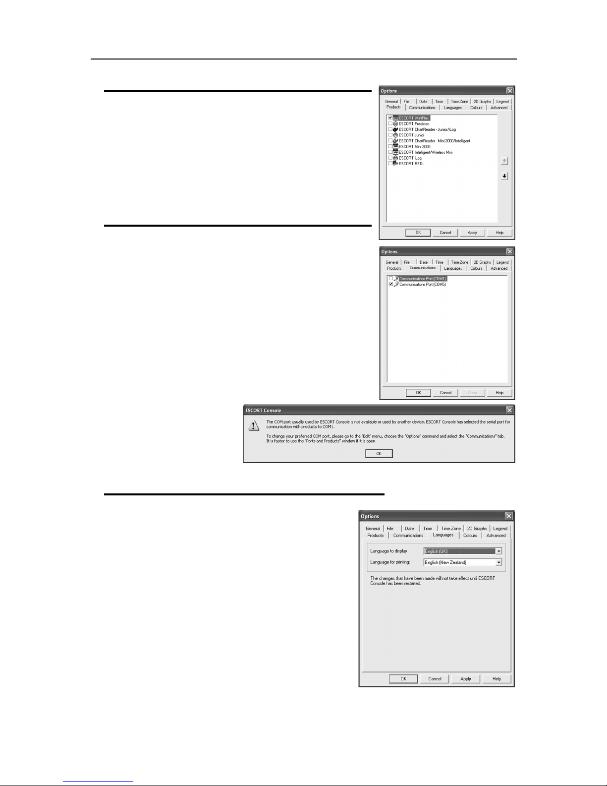
Customizing the software 53
Products
Because ConsolePro supports other logger models, you can select
the appropriate type. Make sure the box called iMiniPlus is ticked,
otherwise the software will not be able to find the logger
By using the arrow buttons down the right of the box, the priority of
the model can be set. This may be important when more than one
logger type is used and may speed up the communication of the
model selected.
Communications
You need to select the correct communication port that is connected
to the iMiniPlus. The box above displays all the ports available to be
used within Console. Please make sure that if a USB adaptor is used
it is connected BEFORE you start Console, otherwise it will not show
in the list. If more than one port is displayed and you are unsure which
is the one connected to the iMiniPlus, tick one and then select the
Download or Program and Configure Wizard. If the iMiniPlus doesn’t
communicate with the software then select another port until you are
successful.
If a USB adaptor has been used but removed, ConsolePro Software
will default to COM1. If this cannot be used, you must close the
software, reconnect the USB adaptor (COM5 shown above) and
restart ConsolePro again.
Note:
If no Com Port is
available, you cannot
communicate with a logger, but
you can view data files.
Languages
ConsolePro has multi language support. If a change is made it
will not take effect unless ConsolePro has been restarted.
Page 56
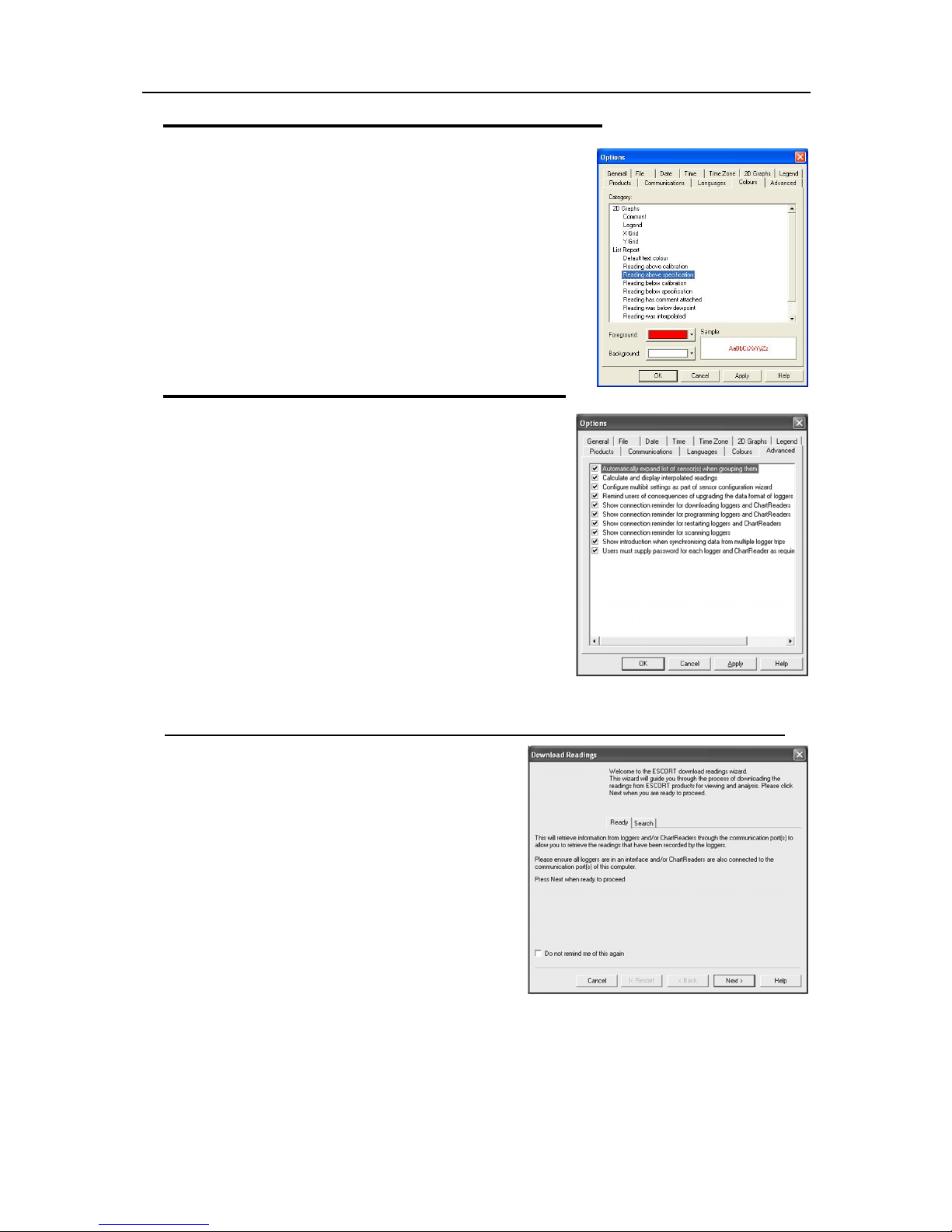
54
Colors
2D Graphs and List Reports can be customized to your color
preferences.
Advanced
The Advanced tab in Options enables you to select or deselect
certain parts of the ConsolePro software program. See descriptions
below.
These options not apply to iMiniPlus:
Automatically expand list of sensors(s) when grouping them
Calculate and display interpolated readings
Configure multibit settings as part of sensor configuration wizard
Remind users of consequences of upgrading the data format of
loggers and ChartReaders
Show connection reminder for scanning loggers
Users must supply password for each logger and ChartReader as
required
Show connection reminder for downloading loggers and ChartReaders
This description box appears at the start of the download
wizard and can either be selected or disabled through the
Advanced tab or disabled by ticking the “Do not remind me
of this again” box at the bottom.
Page 57
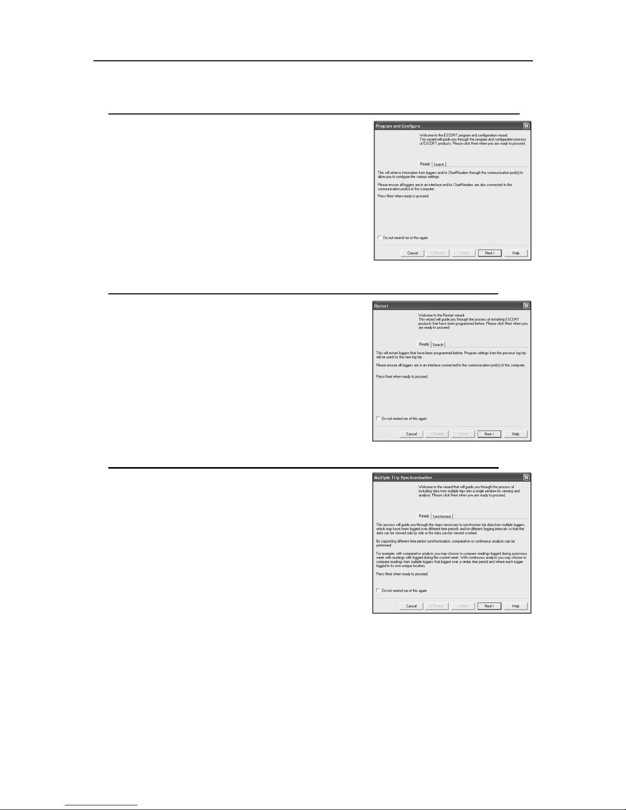
Menus and Toolbars 55
Title bar
Menu bar
Show connection reminder for programming loggers and ChartReaders
This description box appears at the start of the program and
configuration wizard and can either be selected or disabled through
the Advanced tab or disabled by ticking the “Do not remind me of
this again” box at the bottom.
Show connection reminder for restarting loggers and ChartReaders
This description box appears at the start of the Restart wizard and
can either be selected or disabled through the Advanced tab or
disabled by ticking the “Do not remind me of this again” box at the
bottom.
Show introduction when synchronizing data from multi logger trips
This description box appears at the start of the Multi Trip
Synchronization wizard and can either be selected or disabled
through the Advanced tab or disabled by ticking the “Do not remind
me of this again” box at the bottom.
8. Menus and Toolbars
At the top of the screen for the ConsolePro software, just below the title bar, which contains the name of the
software, is the menu system and toolbar for the software. The toolbar provides quick access to some of the
more commonly used functions within the menu system. The menu system contains lists of all the operations
and commands that are available to you while using the software.
Page 58
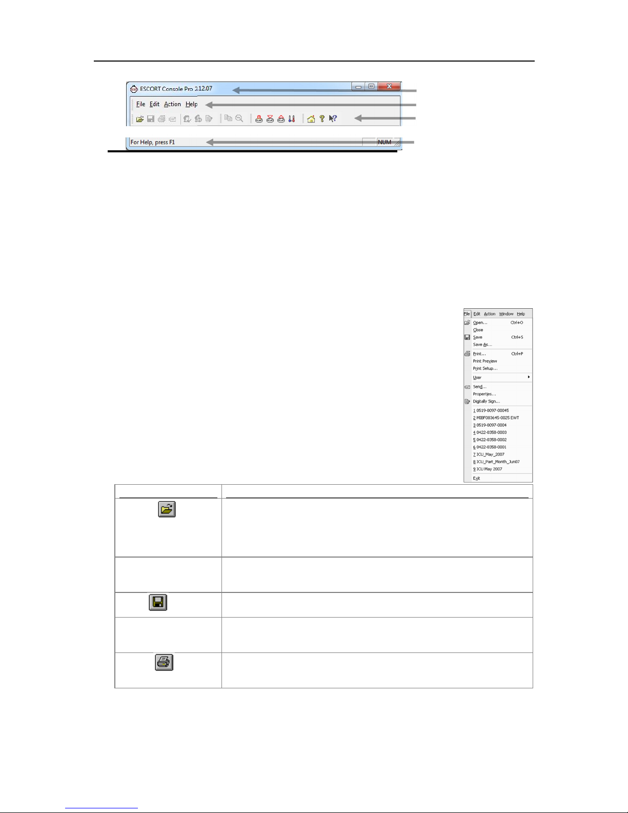
56
Status bar
Command
Explanation
This will display the Open file dialog, which will allow you to open iMiniPlus
File
under
Options
.
Close
This command will close all windows that are displaying information about
command will not be visible.
This will save any changes you have made to the iMiniPlus file to your disk
drive.
Save As...
This will display the Save As file dialog, which will allow you to save a copy
same or different file name.
This will open a window allowing you to print a copy of the iMiniPlus file to
explained in the section "
Printing the results
".
Toolbar
Menu commands
The menu system has been separated into groups of related commands. Each of these menu groups is
explained in more depth in the subsequent sections. The software will only display the menu groups and
commands within each menu group that are appropriate depending on what you are currently doing with the
software.
You may also see that some of the menu commands have a reference after the command name, for example
Ctrl+O. These represent key strokes on the keyboard that instruct the software to perform the appropriate
command, without out the need to select the menu or toolbar command. For example to cause the command
to be performed you must press and hold down the first key mentioned while pressing the other key once.
When letters are used in the key reference, for example Ctrl+O, it does not matter whether or not the caps
lock is on or off.
File Menu
The "File" menu contains commands that generally relate to an iMiniPlus file as a whole.
An iMiniPlus file contains a variety of information that relates to a data set representing
readings that were recorded over a discrete period of time by a single iMiniPlus. The File
menu will appear similar to the following picture.
The following table outlines the commands and the explanation of each command that
may appear in the "File" menu when using the ConsolePro software:
Open... ( )
Save ( )
Print... ( )
files that contain readings previously retrieved and saved as “Logger
Compact File (.lcf)” format
It will start at the folder defined in the
the open file that is currently selected. If no files are currently open this
of the file currently being displayed in the same or different folder with the
an output device, which will typically be a printer. This command is further
Default Folder
settings section in
Page 59
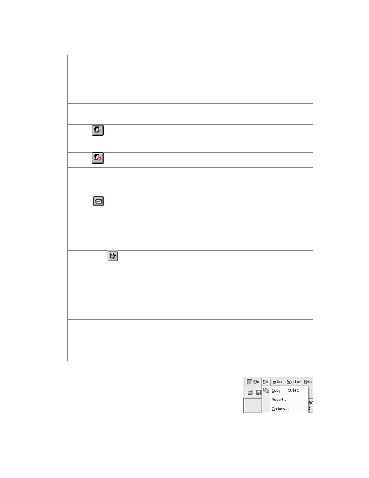
Menus and Toolbars 57
Print Preview
This will change the display mode of the software to show you a copy of
mode.
Print Setup...
This will open a window allowing you to view and/or adjust one or more of
your printer's settings.
User
When User Admin software is installed, users must logon to the software
not installed this feature will be greyed out.
This allows a user to logon to and use the ConsolePro software. Therefore,
then this command is not visible.
Log Off
This allows the currently logged on user to logoff the ConsolePro software.
If there is no currently logged on user, this command is not visible.
This allows the currently logged on user to modify their password that they
administrator has granted the appropriate user permissions.
This will help you send, by email, the currently open and selected file to
"
Sending a file by email direct from Console
".
This will open a window that will display the information about the file that is
Windows Explorer.
This will open a window to display a list of digital signatures that have been
"
Digital signatures
".
1, 2, 3, etc
This portion of the menu represents a list of the most recently files you
Options
.
Exit
This command will exit and close down the ConsolePro software. Any files
to save it or not.
how a printout of the currently selected file and window would look like. In
"Print Preview" mode you will not be able to zoom in or out of a graph.
Click “Close” to exit the "Print Preview" mode and return to normal display
prior to being permitted to use the software. When User Admin software is
Log On ( )
( )
Change Details
Send
... ( )
Properties
Digital Sign
...
... ( )
...
this command will only be available if the ConsolePro software is connected
to the User Admin software. If a user is already logged on to the software,
use to logon to the ConsolePro software. This command will only be
available if User Admin software is installed and the User Admin
another user without the need to exit to your email software or to deal with
file attachments. This command is explained in further detail in the section
being displayed and currently selected. This same window and information
will be displayed if you view the properties of the file from Microsoft
included with the file. It also allows you to add and print this list of digital
signatures. This command is explained in further detail in the section
have viewed. To reopen one of these files, simply click on the entry (name
of the file) to open. If a file that you want to view is not included in this list,
you may use the "Open..." command included in this menu. The number of
files included in this list can be adjusted through the "
File
" section of the
that you currently have open will also be closed automatically for you. If a
user is currently logged on to the ConsolePro software when the
ConsolePro closes, the user will be automatically logged off. F you have
downloaded data from a logger and not saved it, you are prompted whether
Edit Menu
The "Edit" menu contains commands that generally relate to the contents
of an iMiniPlus file and will appear similar to the following picture.
The following table outlines the commands and the explanation of each
command that may appear in the "Edit" menu when using the ConsolePro
software:
Page 60
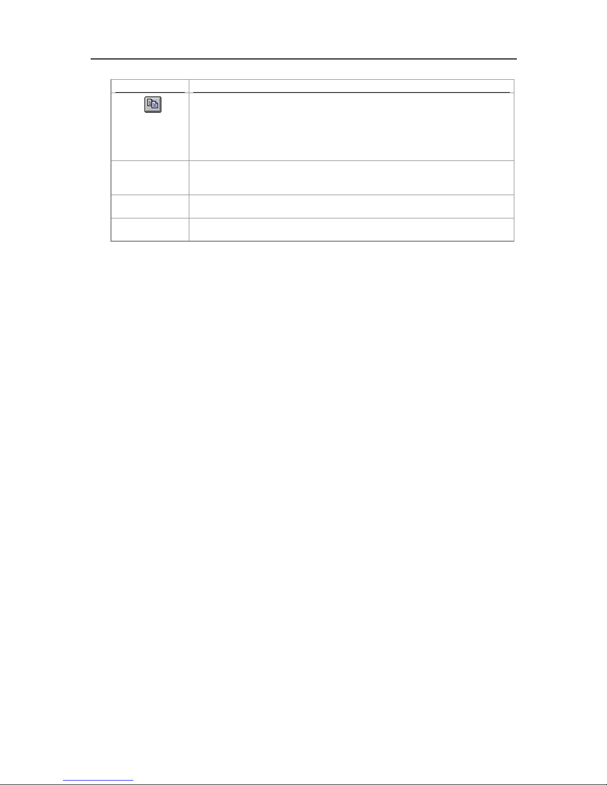
58
Command
Explanation
Places a copy of the contents of the currently displayed window onto the
what part of the data you have scrolled to view.
This opens a box called List Report Options. This allows you to select the date
data file is opened in Console.
This opens a box called Graph Options. This allows you to customize the look of
the graph. This feature is visible only when a Graph is opened in Console.
This will open a window allowing you to customize the software. This command is
further explained in the chapter "
Customizing the software
".
Copy ( )
Report…
Graph…
Options...
clipboard, which can then be pasted into any Windows® application. If you are
copying a graph, the graph at its current zoom range is copied to the clipboard. If
you are copying from one of the tabular style windows (Readings or Summary),
then the entire contents of the window are copied to the clipboard, regardless of
and time range you want to view. This feature is visible only when a Readings
Page 61
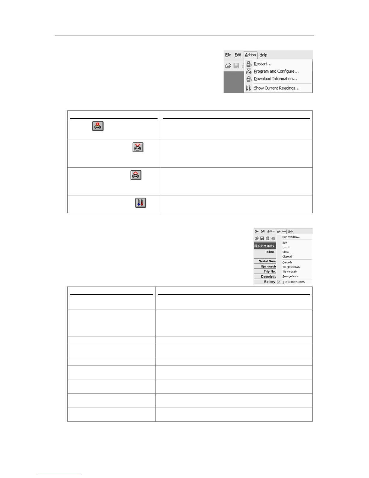
Menus and Toolbars 59
Command
Explanation
This will display a wizard that will help you to restart an
previous settings for the new log trip.
This will display a wizard to help you through the necessary
iMiniPlus for use
".
This will display a wizard to help you through the necessary
the chapter "
Results from iMiniPlus
".
Command
Explanation
New Window
Opens a new window that contains a copy of the information of
the currently selected window.
Split
Use this command to split the active window into panes. You
enter to leave the splitter bars in their new location.
Unsplit
Removes the split panes.
Close
Closes the currently selected window within the ConsolePro
software.
Close All
Closes all the windows within the ConsolePro software.
Cascade
Arrange all the windows within the ConsolePro software in an
overlapping style.
Title Horizontally
Arrange all the windows within the ConsolePro software as
horizontal non-overlapping tiles.
Title Vertically
Arrange all the windows within the ConsolePro software as
vertical non-overlapping tiles.
Arrange Icons
Arrange all the minimized windows within the ConsolePro
software at the bottom of the main window.
Action Menu
The "Action" menu contains commands that generally relate to the
usage and interaction with loggers.
The following table outlines the commands and the explanation of
each command that may appear in the "Action" menu when using
the ConsolePro software:
Restart ( )
Program and Configure...( )
iMiniPlus that has been programmed before, using the
steps to prepare the iMiniPlus for its next use. This command
is explained in further detail in the chapter "
Download Information... ( )
steps to retrieve a copy of the recorded readings stored within
the Escort(s). This command is explained in further detail in
Show Current Readings... ( )
This feature is not available for the iMiniPlus.
Window Menu
The "Window" menu contains commands that relate to the management of
each Window open within the ConsolePro software that displays the contents
of an iMiniPlus file.
The following table outlines the commands and the explanation of each
command that may appear in the "Window" menu when using the ConsolePro
software:
Preparing
may then use the mouse or the keyboard arrows to move the
splitter bars. When you are finished, press the mouse button or
Page 62
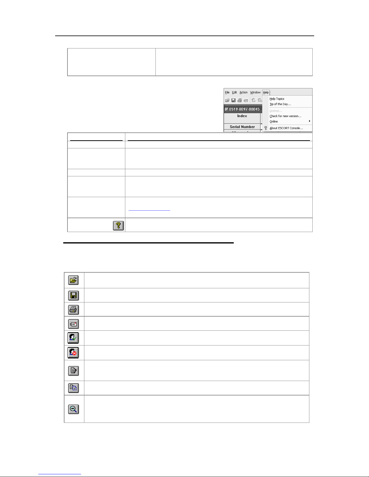
60
1, 2, 3, etc
The tick mark beside these entries indicates the window that is
appropriate entry on this list.
Command
Explanation
Help Topics
Opens a window that contains the online help.
Tip of the Day…
Displays a number of helpful suggestions about using the ConsolePro
of
“Options”.
License
Not required - No longer available
Check for new
This is a simple way of checking to see if there is a newer version of this
in the chapter "
Getting updated software
".
Online...
This will open your default Internet browser software and display
connected to the Internet to successfully display the website.
About
Console... ()
Display the version information about the ConsolePro software that you are
using.
contain previously retrieved readings.
Creates a new blank email for sending a copy of the currently selected open file as an
attachment to a recipient of your choice.
This will log a user onto the ConsolePro software provided User Admin software is also
installed.
This will log the user off the ConsolePro software provided User Admin software is also
installed.
Displays information about any digital signatures included in the currently selected open file,
print a copy of the digital signatures.
Places a copy of the currently displayed information to the Windows clipboard so that you can
paste it into another Windows software package.
Zooms out one level of the actively displayed graph. If you are displaying a graph and this
zooming out.
currently selected. If you want to change the currently selected
window to one of the windows listed, just click/select the
Help Menu
The "Help" menu contains commands that relate to providing you
with help and assistance with using the ConsolePro software.
The following table outlines the commands and the explanation of
each command that may appear in the "Help" menu when using
the ConsolePro software:
version...
software. This can be enabled at the software startup. See the
software available for download. This command is explained in further detail
www.cryoapk.com
This command requires that your computer be currently
“General”
tab
Toolbar commands
Each picture on the toolbar represents a unique command. The pictures that are included on the toolbar
represent the following commands:
This will display the file open window to allow you to locate and open iMiniPlus files that
Save a copy of the iMiniPlus data to a file on your disk drive.
Opens the window that will allow you to print a copy of the iMiniPlus data to a printer.
which is also allows where new digital signatures can be added to the file and where you can
function is not available, then all data that is available to be displayed is currently been
displayed and therefore there is no more additional information that can be displayed by
Page 63
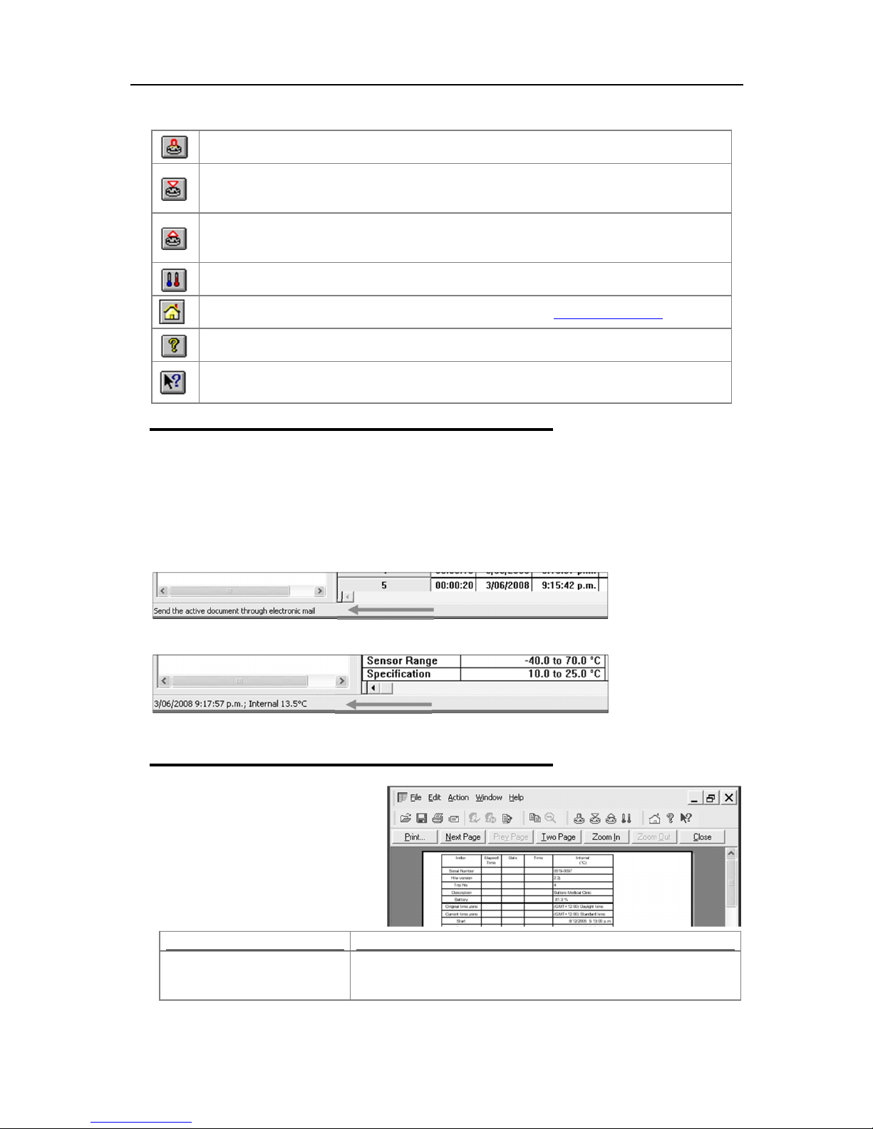
Menus and Toolbars 61
Opens Restart Wizard that reprograms iMiniPlus using previous logging settings for new
logged trip.
Opens Program and Configure Wizard to help you through the necessary steps to prepare the
"
Preparing iMiniPlus for use”
Opens Download Information Wizard to help you through the necessary steps to retrieve a
further detail in the chapter "
Results from iMiniPlus
".
Command
Explanation
Print...
This will open a window allowing you to print a copy of the iMiniPlus
command is further explained in the section "
Printing the results
".
iMiniPlus for its next use. This command is explained in further detail in the chapter
copy of the recorded readings stored within the Escort(s). This command is explained in
This feature is not available for the iMiniPlus.
Opens your default Internet browser software and display www.cryopak.com
Displays the version information about the ConsolePro software that you are using.
This will allow you to show the help topic on any particular command or topic that you
subsequently select.
Status bar
The status bar is a handy one line instruction of a menu activity or shows the graph co-ordinates. It is
displayed at the bottom left of the ConsolePro window.
To hide or display the Status Bar, choose
Status Bar
Description of the Menu activity. When a menu item is selected the appropriate description will appear in
the Status Bar.
option from the
General
tab.
Options
from the
Edit
menu and uncheck or check
Display the
Displays the date, time and temperature along the x-axis when a 2D graph is displayed.
See sections 2D graphs and View Data in Graph.
Print preview toolbar
The print preview feature, available
through the
will display copy of the data as it would
be included on a print out. When the
software is displaying a file in print
preview mode, an additional toolbar will
appear, similar to the following picture.
File menu
, of the software
file to an output device, which will typically be a printer. This
Page 64
62
Next Page
This will display the next page included in the print out. This button
displayed.
Prev Page
This will display the previous page included in the print out. This
displayed.
One Page
Selecting this button will change the display so that only one page
"Two Page".
Two Page
Selecting this button will change the display so that two consecutive
Once this button is selected it will change to "One Page".
Zoom In
This will zoom in the display of the print out making it appear larger
print out.
Zoom Out
This will zoom out the display of the print out making it appear
in the print out.
Close
This will close the print preview mode of display and make the
between graph display and data listing display, for example.
will be disabled if there are no more pages available to be
button will be disabled if there are no previous pages available to be
is displayed at a time. Once this button is selected it will change to
pages are displayed side by side at the same time. This button will
be disabled if there is only one page in the print out, like a graph.
on the screen. It will not affect what information is included in the
smaller on the screen. It will not affect what information is included
display revert to normal mode, which will allow users to switch
9. Working with Networks
When using and deploying software in a network environment, network administrators often require
additional technical information about the software so they can integrate support for it correctly and
seamlessly. Contact your distributor or Cryopak Verification Technologies for further information.
10. Getting more information
Getting updated software
There will be no further updates in ConsolePro software. The last final version 2.12.07.
Finding your software version
Within the "
which will display a Window similar to the following picture.
Within this window, amongst other information, the full version
number of the software being used is displayed. This information
is useful, for example, to determine if the same software version
is installed on multiple computers and/or if the manual being
referenced refers to the version of software being used.
Help
" menu, is the "About Console..." command,
11. Warranty
The iMiniPlus has a 24 months warranty valid from date of purchase. In the event of a malfunction please
contact your distributor. The warranty has the following exclusions:
1. If the unit has been modified from manufacturer’s specifications.
2. Exposure of the logger to temperatures less than -40°C or greater than 70°C.
Page 65

Dry Ice iMiniPlus 63
MP-OE-N-8-L (Multi use External sensor)
MP-ST-N-8-L (Single use External sensor)
Memory Options
8K; 8032 readings
Program Interval
5 seconds to 18 hours
Time Accuracy
±1 minute per month
Sensors
External
Temperature Range
-100 °C to +40 °C (-148 °F to +104 °F)
±1.0 °C (-100 °C to -80 °C), ±1.8 °F (-148 °F to -112 °F)
±0.7 °C (-50 °C to +40 °C), ±1.3 °F (-112 °F to -58 °F)
±0.6 °C (-50 °C to +40 °C), ±1.0 °F (-58 °F to +104 °F)
Resolution
0.1 °C (0.1 °F)
Sensor Response Time
External Sensor – T90 of 5 minutes in moving air
LCD Operating Range
-20 °C to +70 °C (-4 °F to +158 °F)
Alarm Thresholds
Two
Alarm Configuration
High & low
Bookmark
Yes
User Programmable
Preprogram also available
Start Option
Push button and/or timer
Start Delay
Yes
Stop Option
Yes, Stop button (can be disabled)
Size
83 x 57 x 17mm (excluding lug)
Weight
70 grams (including battery)
Case Material
Polycarbonate/ABS
Battery
3.0V, user replaceable
IP Rating
IP65 (with plastic cap over USB connector)
24 months, excluding battery (Multi use loggers)
One Trip, excluding battery (Single use loggers)
Calibration
Upon request
Accuracy Certificate
Yes
Other Certification
ISO9001:2008, CE, RoHS, EN12830
Battery Life
1-2 years (depending on usage)
Interface
USB (included)
Software
Console Pro
3. Loss or damage caused by the ingress of moisture.
4. Evidence that the printed circuit board has been removed or tampered with.
5. Evidence of mistreatment or abuse.
6. Loss of unit.
7. Batteries are not covered by this warranty.
12. Dry Ice iMiniPlus
Important Notes:
1. Do not place the logger inside the dry ice temperatures, use external probe instead
2. Battery of iMiniPlus is not able to withstand temperatures below -40°C
3. Do not crush or cut the external probe
Specifications
Description Specifications
Product Code
Temperature Accuracy
Preprogram Option
Warranty
Page 66
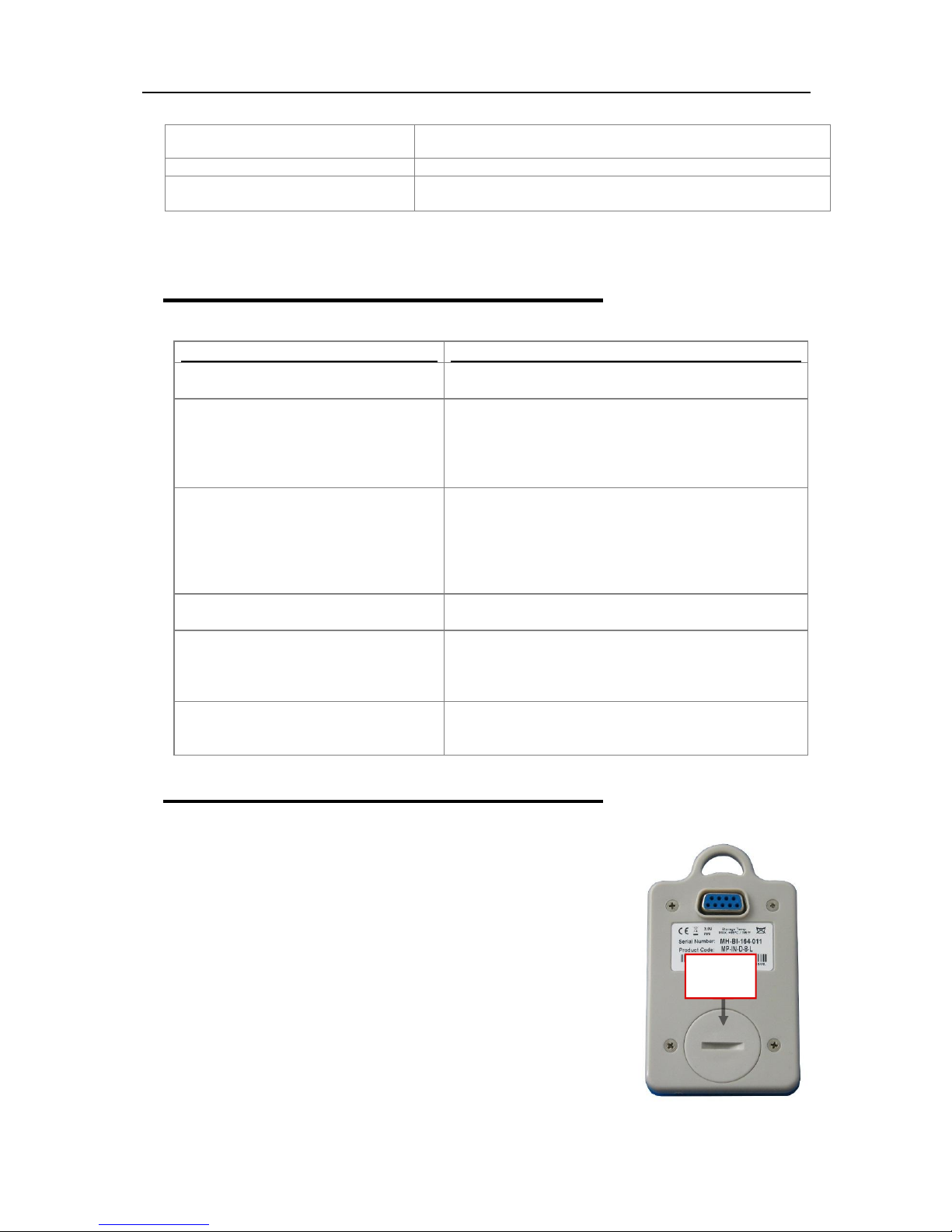
64
Data Export
TXT, CSV, SYLK & LCF
Password protected (programmable using Console Pro Software)
encrypted binary file is generated along with PDF
Problem
Solution
My iMiniPlus appears to be “dead”. There
are no readings on the LCD.
Change the battery using a CR2450
(3V Lithium coin cell.)
The Stop button is not working
Reprogram the iMiniPlus and tick the Enable Stop button
at the next program
The iMiniPlus appears to be working but I
Make sure you have tried all the solutions the Wizard has
to your distributor for service.
My iMiniPlus is reading -40°C / 70°C
/-100°C /+40°C all the time.
The sensor has become damaged. Send the iMiniPlus to
your distributor for service.
The year, date and time on the
The battery has been removed from the iMiniPlus for
Configure. See section Checking the time clock.
When I press the Start button to start my
displays “Stopped”
You have to re-program the iMiniPlus to enable the Start
Configure section
Default File Format PDF & LRF
Security
13. Appendix
Troubleshooting
box in the Startup tab of Program and Configure. See
section Setting the Start and logging duration or Quick
Start Guide section. Note this defaults back to unselected
cannot program it. Software displays error
“ The software was unable to find any
products that it supports….”
downloaded data is incorrect.
iMiniPlus it displays some readings then
Changing the Battery
The iMiniPlus displays battery low symbol on LCD display once battery
voltage falls below 2.8V. The iMiniPlus checks the battery status every
10minutes or when it is interrogated by software i.e. downloading or program
and configure.
To change the battery, turn the iMiniPlus over and unscrew the battery cover
on the back with a coin. Remove the old battery and exchange for a fresh
one. Be careful not to damage the plastic thread on the inside of the battery
compartment when removing the old battery, otherwise the battery cover may
not fit securely back and in turn may allow moisture to enter the logger.
Note, if the battery is removed for a period of longer than 30 secs, the
internal clock will need adjustment back to the present data and time. This
is done through the Program and Configure Wizard. See section Checking
the time clock.
suggested.
Check you have the current version of ConsolePro
software
If it still does not communicate you will need to return it
more than 30 seconds. Re-program the iMiniPlus and
select the PC clock in the Date/Time tab of Program and
button to initiate another logging cycle. See Program and
Battery
compartment
Page 67
Contact details 65
14. Contact details
If you require further information regarding CRYOPAK Verification Technologies, Inc.
products please contact us at:
USA
Mailing Address: PO Box 309, Buchanan, VA 24066
Office: 120 Parkway Drive, Buchanan, VA 24066
Phone: +1-540-254-1433
+1-732-346-9200 Ext. 150
Fax: +1-540-254-2433
Email: [email protected]
CANADA
FRANCE
Address: TCP Cryopak France
1 Rue Berthelot
Z.I. La Maine
76150 Maromme
Phone: +33 2 32 82 59 65
Email: [email protected]
You can find additional information regarding all of our products on our website:
www.cryopak.com
http://www.cryopak.com/en/verification-products/
Copyright © 2016 Cryopak Verification Technologies, Inc. All rights reserved.
 Loading...