

Esco TSC-1008MV, TSC-1008, TSC-1008V-R2, TSC-1008MV-R1, TSC-1012MV Installation And Operation Manual
...
. . . 8 AND 12 STATION EXECUTIVE SERIES INTERCOM
INSTALLATION AND OPERATION
DESCRIPTION:
ESCO’s EXECUTIVE SERIES intercom features 8 or 12 station bi-directional communication, high quality gooseneck
microphone, voice activated talk circuit and three powerful 20 WATT output amplifiers for clear voice reproduction under
the most severe circumstances.
SPECIFICATIONS:
Ì
Intercom size: 7.5”D x 9.0”W x 4”H (including feet)
Ì
Junction Box size: 4.5”D x 10.0”W x 2.0”H (including mounting tabs)
Ì
Weight: 7.5lbs (including power transformer)
Ì
Two quick disconnect interconnection cables (6’ standard)
Ì
120VAC stepped down to 18VAC via UL approved wallmount transformer
FEATURES:
Ì
User friendly
Ì
Custom tailored voice spectrum microphone
Ì
VOX (Voice Activated “hands free” talk switching)
Ì
Silent standby (deselected speaker station)
Ì
Simultaneous communication with all remote
stations
Ì
Lights to indicate call locations and station status
Ì
Hold memory for multiple conversations
Ì
Flashing indicator and audible tone for customer call
in alert
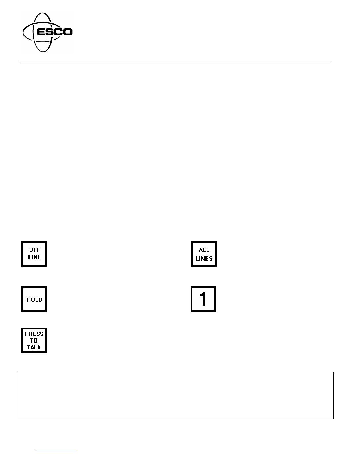
STATION STATUS L.E.D. CODE AND SWITCH FUNCTIONS:
Deactivates all stations. Intercom
should remain in this mode when not
in use. Red OFF LINE LED flashes
indicating OFF LINE mode.
Depressing HOLD causes station
status LED’s to illuminate yellow as a
reminder of a previously active station.
Depressing this switch causes the intercom to switch from the listen mode to the talk mode. Station status
indicators illuminate green for listen and red for talk mode.
Ì
External input for music or message repeater
Ì
Dedicated listen amplifier
Ì
Three 20 WATT output amplifiers
Ì
Field adjustable talk out volume
Ì
Operator adjustable talk out volume
Ì
Chemical resistant long life membrane keypad
Ì
Dust, moisture and smoke resistant internal speaker
Ì
Grounded chassis for safety
Activates all stations simultaneously,
enabling monitoring and broadcasting to
all remote stations at once.
Eight or twelve station selector switches
to activate single stations for two-way
communication.
FOR FURTHER INFORMATION CONTACT THE ESCO OFFICE IN YOUR AREA
P/N 0219-0021A
ESCO Services, INC. ESCO Services, INC. ESCO Services, INC.
Denver, Colorado
TOLL FREE ...... (800)824-5579
In Colorado ....... (720)382-2000 In Florida.............. (813)855-9466 In Michigan...........(586)254-3367
TELEFAX .......... (720)382-2001 TELEFAX............. (813)855-1649 TELEFAX .............(586)254-2767
Tampa, Florida
FREE ......... (800)237-9710
TOLL
Sterling Heights, Michigan
TOLL FREE..........(800)521-1808

RECOMMENDED SPEAKER CABLE:
All speaker cable should be of a shielded or twisted-pair type containing 18 or 22 gauge wire. Cable shields should be
attached to the shield ground connections in the junction box only. Use of shielded or twisted pair cable provides clearest
communication and easiest connection to each Sub-station speaker. All speaker cables must be routed through a conduit
that is SEPARATE
from those containing 120VAC power wiring.
DO NOT UNDER ANY CIRCUMSTANCES ROUTE AUDIO CABLES IN THE SAME CONDUIT WITH 120VAC WIRING.
THIS VIOLATES THE NATIONAL ELECTRIC CODE AND PRESENTS A HAZARD.
INSTALLATION GUIDELINES:
A) Wallmount transformer should have a dedicated grounded 120VAC line.
B) Speaker hook-up wire should be 18-22 gauge shielded or twisted pair cable.
C) Run speaker cable separately away from high voltage power wiring.
D) Sub-station speakers mounted in close proximity of the Master-station may result in a howl (acoustical feedback)
when either one calls the other. This condition can be corrected by lowering volume or repositioning the substation
speaker.
E) The use of ESCO Speakers and Call switches is recommended for optimum performance.
F) Mount Speakers and Call switches according to their installation and application guide.
INSTALLATION OF THE ESCO EXECUTIVE SERIES INTERCOM:
1) Run an appropriate length of speaker cable from each remote speaker and call switch to the area where the intercom
junction box is to be located. (Tagging wire ends is recommended to avoid confusion when the final connections are
made)
2) Strip 3/16” of insulation from the end of each wire and twist the strands together.
3) Remote speakers and call switches should be connected to the terminals of the junction marked Call Connections
and Speaker Connections per the drawing provided in this instruction set.
4) Connect supplied cables from junction box to intercom.
5) Plug wallmount transformer (included) into a dedicated grounded 120VAC outlet.
6) Turn on power switch (located on the rear of the intercom) and check the operation of all connected speakers and call
switches. If the talk out volume is to low or there is acoustical feedback present, adjust the talk out speaker volume
(located underneath the intercom) accordingly.
7) Check the sensitivity of the VOX circuit. A proper adjustment should trip the intercom into the talk mode when
speaking in a normal voice into the microphone from a distance of 1 to 2 inches. The VOX sensitivity adjustment is
located underneath the intercom.
8) To ensure proper warranty protection, be sure to fill out the warranty registration information and return immediately.
INSTALLATION OF MUSIC OR MESSAGE PLAYER:
Music and/or prerecorded messages may be transmitted to all remote stations that are deselected (in standby) or off-line.
1) Install Model SPK-1010 impedance matching transformer (p/n 0204-0080 sold separately) to the External Input
terminals of the junction box. The SPK-1010 prevents multi-speaker loading to the customer supplied amplifier
source. See enclosed diagram.
2) Attach the 8 OHM output of the message player/external amplifier to the (black) input wires of Model #SPK-1010
impedance matching transformer. Music and/or prerecorded messages will be transmitted to all remote stations that
are deselected (in standby) or in off-line mode.
2
 Loading...