

Esco SWT-MIP-0.2-*, SWT-MIP-0.5-* Service Manual
Esco Life Science Laboratory
Equipment Solutions
PCR Thermal Cyclers • Real-time PCR System • Microplate Shakers / Incubators
Thermal Cyclers
Service Manual

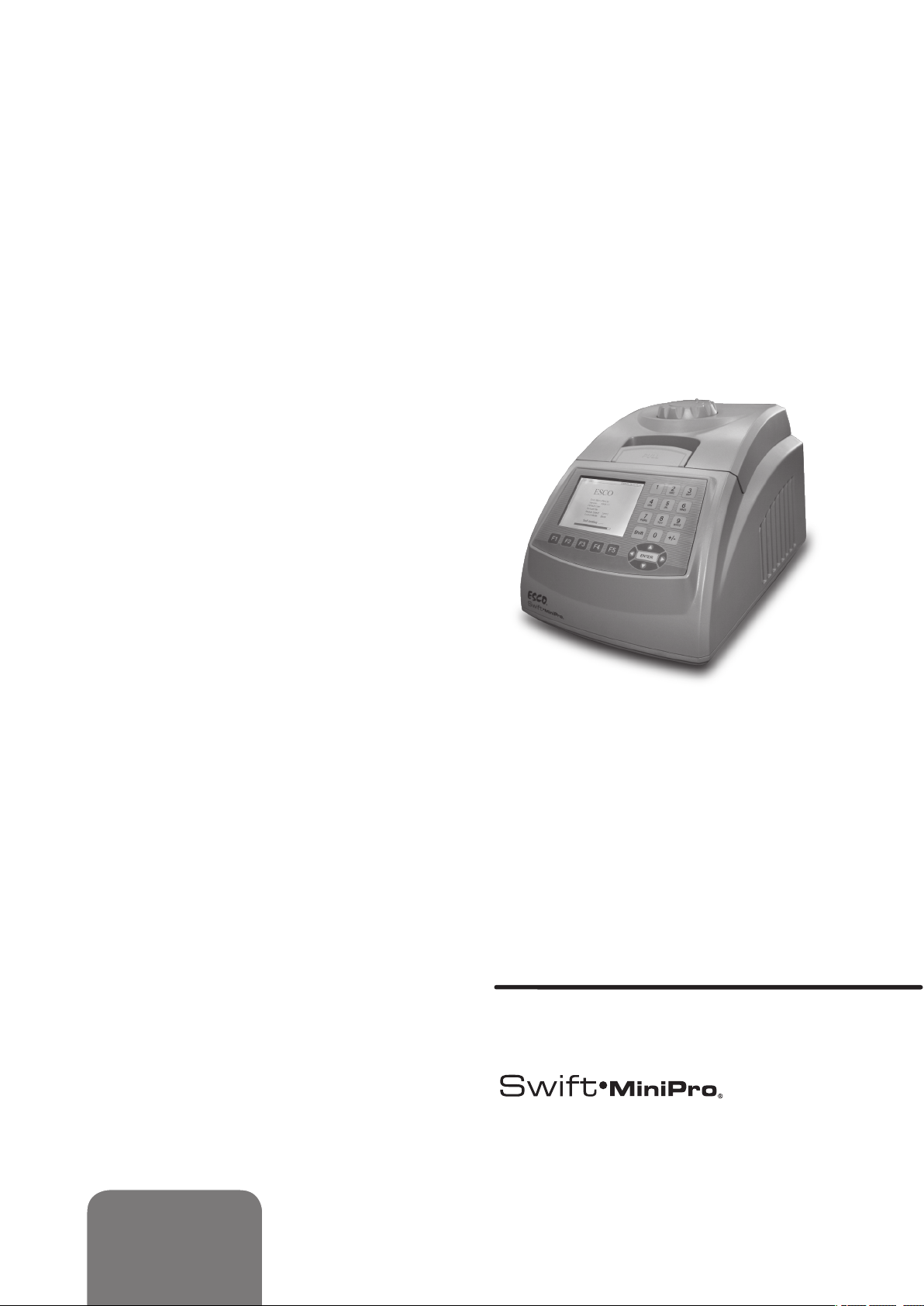
Thank you for purchasing the Esco Swift MiniPro
Thermal Cycler. Please read this manual thoroughly to
familiarize yourself with the many unique features and
exciting innovations we have built into cycler. You can
view this manual online at www.pcrthermalcyclers.com,
where you can find many other resources to help you
enjoy many years of productive and safe use of your
Esco equipment.
For Technical Service, contact
Esco Healthcare Pte. Ltd.
21 Changi South Street 1 • Singapore 486 777
Tel +65 6542 0833 • Fax +65 6542 6920
www.pcrthermalcyclers.com • sales@pcrthermalcyclers.com
US $ 50.00
Europe € 40.00
Additional manuals can
be purchased through
your Esco Distributor
Esco SWT-MIP Service Manual (Version 1.0)
Released August 2009
Service
Manual
Thermal Cyclers

Thermal Cyclers • Service Manual

i
Table of Contents
:
Table of Contents
Table of Contents ............................................................................................................................. i
1. Introduction .............................................................................................................................. 1
1.1 Products Covered .........................................................................................................................................1
1.2 Basic product information ..........................................................................................................................1
1.2.1 Quick View .................................................................................................................................................... 1
1.2.2 Technical specication summary table........................................................................................................... 3
1.3 Security Notes ..............................................................................................................................................4
1.4 Guidance.......................................................................................................................................................4
1.5 Maintenance tools .......................................................................................................................................4
2. Service Procedures .................................................................................................................... 7
2.1 Fan Replacement ................................................................................................................................... 7
2.2 LCD replacement..........................................................................................................................................8
2.3 Hot Lid adjust knob repair and replacement ....................................................................................... 9
2.4 Hot lid repair and replacement. ...............................................................................................................10
2.5 Heating and Cooling parts Replacement ........................................................................................... 13
2.6 Printed Circuit Board Recognitions and replacement ............................................................................16
3. Troubleshooting .............................................................................................................................17
Appendix
Appendix 1: Printed Circuit Board Layout ........................................................................................33
Appendix 2: Wiring Diagram ..............................................................................................................37
Appendix 3: Spare Part List .................................................................................................................39

Thermal Cyclers • Service Manual
CHAPTER 1
INTRODUCTION
1.1 Products Covered
This manual is applicable and specific to the following Esco products.
Swift MiniPro Thermal Cycler (SWT-MIP)
Rated voltage (V) With 24 X 0.2ml block With 18 X 0.5ml block
Chapter 1 • Introduction
1
:
100-120VAC, 50/60Hz
200-240VAC, 50/60Hz
1.2 Basic product information
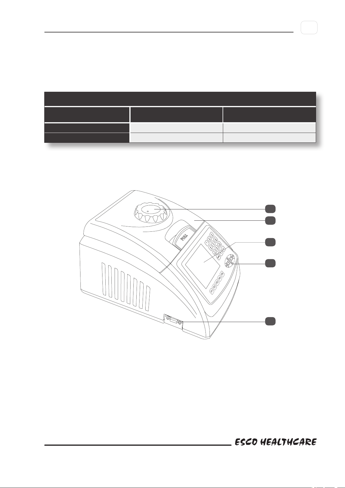
1.2.1 Quick View
SWT-MIP-0.2-1 SWT-MIP-0.5-1
SWT-MIP-0.2-2 SWT-MIP-0.5-2
8
1
2
3
4

2
:
Chapter 1 • Introduction
Thermal Cyclers • Service Manual
5
6
7
3
:
Chapter 1 • Introduction
NO NAME DESCRIPTION NOTE
Turn the knob counter-clockwise before closing
1 Hot lid and Knob The Knob is for adjusting the height of the Hot Lid
2 LCD Screen
3 Keyboard For setting and controlling.
4 RS232 interface PC interface for software upgrading
5 P o w e r S w i t c h Turn the equipment ON/OFF.
6 P o w e r S o c k e t Connect power supply.
7 Fuse Socket
8 Unlocking Device Loose the hot lid knob
Display protocol, conditions and other information during
setting and running.
Install fuse in the socket to protect equipment from over-
current.
the lid. Note that the knob can be tightened by
turning it clockwise, and can be loosened by
turning counter-clockwise.
The fuse specications are as follows: 250V
2.5A(or 125V 5A), φ5×20mm. Fuse should
be replaced by one that complies with these
specications.
If hear click sound at the beginning of turning
the knob clockwise and counter clockwise,
press the unlocking device and turn the knob
counter-clockwise for two rounds to loose the
knob
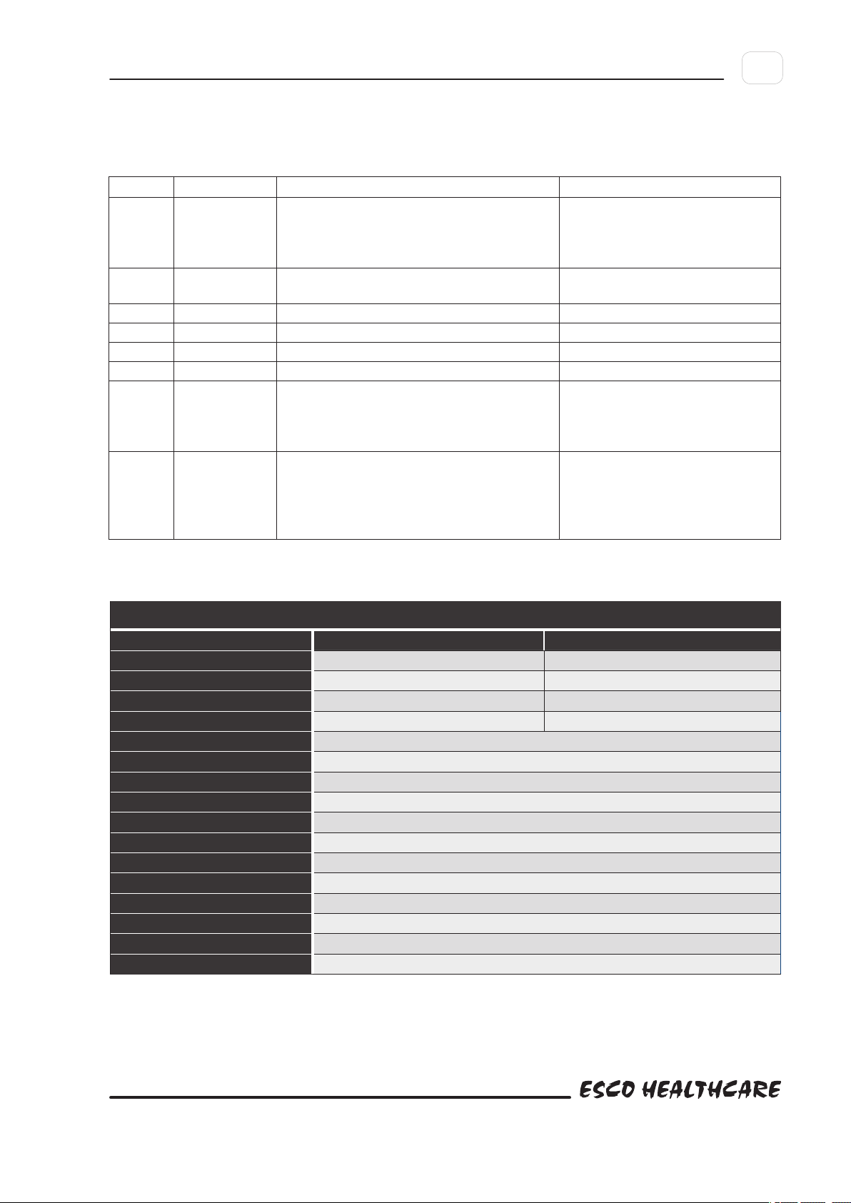
1.2.2 Technical specification summary table
General Specifications, Swift MiniPro Thermal Cycler
Model Code SWT-MIP-0.2-* SWT-MIP-0.5-*
Sample Capacity 24 x 0.2 mL 18 X 0.5 mL
Applicable Consumables 0.2 mL tubes, 3 X 8 strips, 24-well microplates 0.5 mL tubes
Max. Heating Rate 5.0°C / sec 4.0°C / sec
Max. Cooling Rate 4.0°C / sec 3.0°C / sec
Temperature Uniformity ±0.3°C
Temperature Accuracy ±0.3°C
Temperature Range 4°C - 99°C
Hot lid Temp. range 30°C - 110°C
Temp. Control Mode Block mode or tube mode
Display
Protocol Capacity
PC Interface
Dimension (W x D x H)
Weight
Electrical
Warranty
212 × 297 × 200 mm (8.3” × 11.7” × 7.9”)
3 years for main body, 2 years for blocks
Graphical LCD
100 protocols
RS232 for software updates
3.2 kg (7 lbs)
100-240VAC 50/60Hz 200W

4
:
Chapter 1 • Introduction
Thermal Cyclers • Service Manual
1.3 Security Notes
i. Turn the power OFF and unplug the power cord before performing any procedure.
ii. Please read all the instructions thoroughly before maintenance. Always follow this service manual. Keep this service
iii. Engineers must inspect and ensure operation of the equipment is completely back to normal after maintenance.
1.4 Guidance
Pay attention on the following before hand.
i. Investigate :-
• Situationoftheequipmentasoperating
• Previousmaintenancerecord
• Symptomofthefailure
• Hardwareenvironment
• Structureoftheequipment
• Yearsoftheequipmentbeused
manual well for future reference and review it as necessary.
ii. Check power supply.
iii. Check installation of the equipment.
iv. Clean internal of the equipment to eliminate failures caused by dust, dirt, redundant solder, welding oil.
v. Read all the instructions thoroughly before maintenance to ensure full understanding.
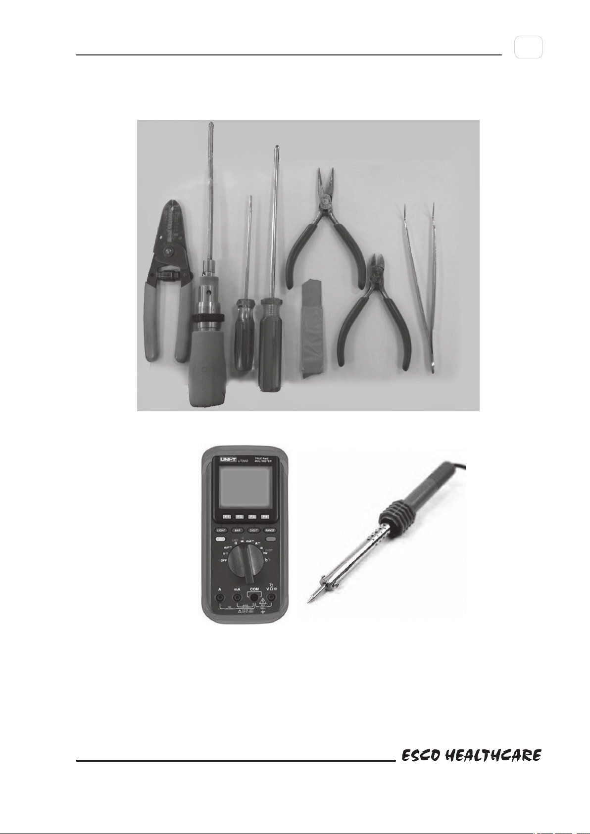
1.5 Maintenance tools
• Wire-strippingpliers,wirestripper
• TorquescrewdriverΦ3
• WordscrewdriverΦ2
• CrossscrewdriverΦ3
• Sharpnosepliers,diagonalcuttingnippers
• Penknife
• Tweezers
• Multimeter
• Electriciron
5
:
Chapter 1 • Introduction
Besides, a multi-channel temperature acquisition device is needed for temperature uniformity and accuracy testing.

Thermal Cyclers • Service Manual
Chapter 2 • Service Procedures
CHAPTER 2
SERVICE PROCEDURES
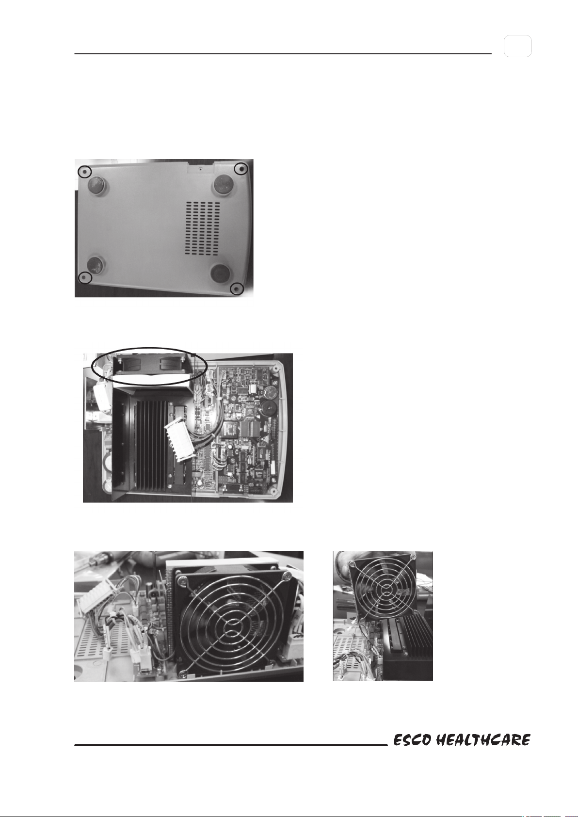
2.1 Fan Replacement
2.1.1 Remove the screws at the bottom of the unit. Refer to Fig.1. Then remove the cover.
Fig.1
7
:
2.1.2 The location of the fan is as Fig.2
Fig.2
2.1.3 Remove all connectors and take out the fan. As Fig. 3 and Fig.4
Fig.3 Fig.4
8
:
Chapter 2 • Service Procedures
Thermal Cyclers • Service Manual
2.14 Replace a new fan.
Notes: Please note the air flow direction of the fan and the polarity of the connection wire when replacing the fans. Please mark
them to avoid forgetting the correct sequence and make sure the connection is secure.
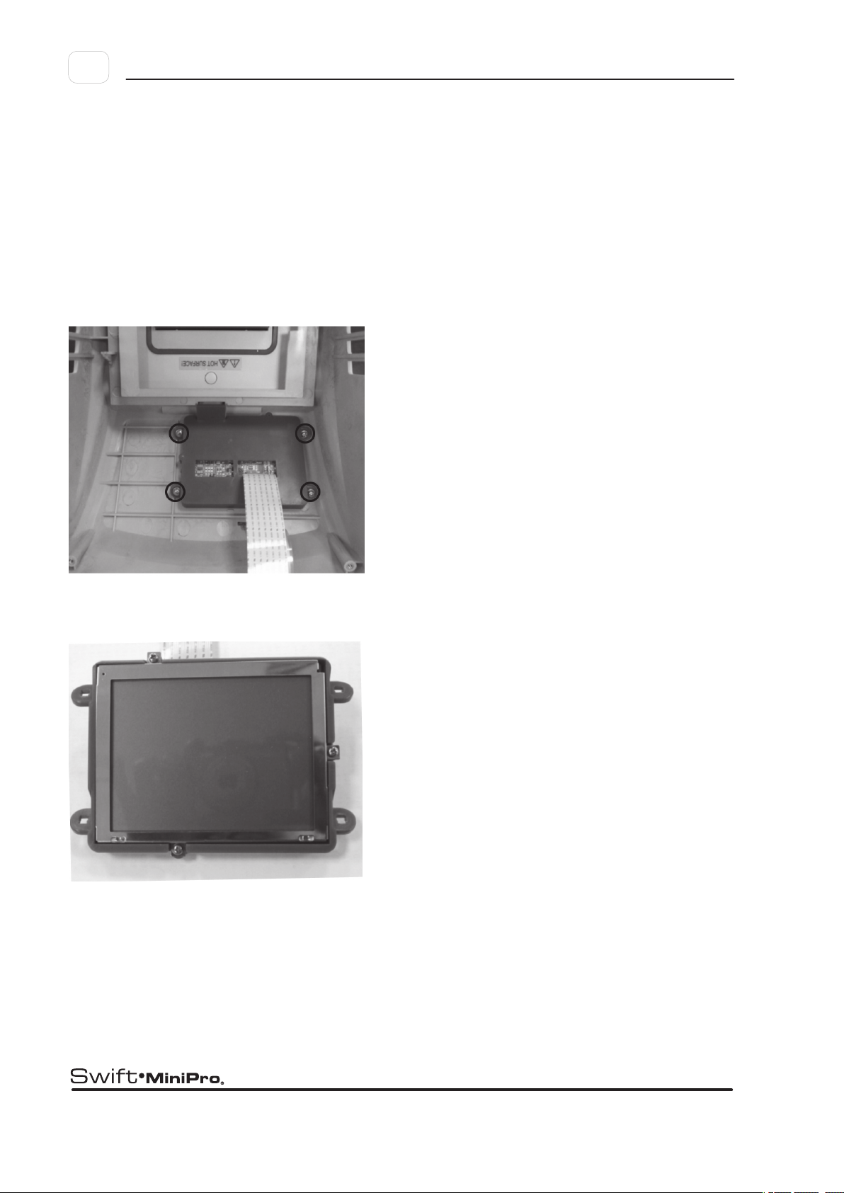
2.2 LCD replacement
2.2.1 Remove the front cover and see the LCD control board as Fig.5
Fig.5
2.2.2 Remove the screws as Fig.5, and get the LCD and LCD control board which are combined into one part. As Fig.6
Fig.6

9
:
Chapter 2 • Service Procedures
2.3 Hot Lid adjust knob repair and replacement
2.3.1Useatweezerstoremovethesmallhotlidlockdevice.AsFig.7
Fig.7
2.3.2 The cover will be removed together with the lock device. As Fig.8
Fig.8
2.3.3 Remove the small rotate metal ring. As Fig. 9
Fig.9
 Loading...