

Page 1
User
Manual
Thank you for purchasing this Esco Ultra-Low Temperature
Freezer. Please read this manual thoroughly to familiarize
yourself with the many unique features and exciting
innovations we have built into your new equipment. Esco
provides many other resources at our website,
www.escoglobal.com, to complement this manual and help you
enjoy many years of productive and safe use of your Esco
products.
Esco Technologies, Inc.
2940 Turnpike Drive, Units 15-16 • Hatboro, PA 19040, USA
Toll-Free USA and Canada 1-877-479-3726
Tel 215-441-9661 • Fax 215-441-9660
us.escoglobal.com • [email protected]
Esco Micro Pte. Ltd.
21 Changi South Street 1 • Singapore 486 777
Tel +65 6542 0833 • Fax +65 6542 6920
www.escoglobal.com • [email protected]
Page 2

Copyright Information
© Copyright 2011 Esco Micro Pte. Ltd. All rights reserved.
The information contained in this manual and the accompanying product is copyrighted and all rights are
reserved by Esco.
Esco reserves the right to make periodic minor design changes without obligation to notify any
person or entity of such change.
Lexicon® is a registered trademark of Esco.
“Material in this manual is provided for informational purposes only. The contents and the product described in
this manual (including any appendix, addendum, attachment or inclusion), are subject to change without
notice. Esco makes no representations or warranties as to the accuracy of the information contained in this
manual. In no event shall Esco be held liable for any damages, direct or consequential, arising out of or related
to the use of this manual.”
Page 3
Ultra-Low Temperature Freezer
i
Introductory Page
i
Table of Contents
iii
Warranty Terms and Conditions
v
Introduction
v
1. Products Covered
v
2. Safety Warning
v
3. Limitation of Liability
v
4. European Union Directives on WEEE and RoHS
vii
Declaration of Conformity
1
Chapter 1 – Product Information
1
1.1 About Lexicon Ultra-Low Temperature Freezers
1
1.2 Labels
2
1.3 Quick View
2
1.3.1 Front Quick View
3
1.3.2 Back Quick View
5
Chapter 2 – Installation
5
2.1 General Requirements
5
2.1.1 Location Requirements
6
2.1.2 Environmental Requirements
6
2.1.3 Power Requirements
6
2.2 Installation
6
2.2.1 Unit Leveling
7
2.2.2 Shelves Installation
8
2.2.3 Omega Brackets Installation
8
2.2.4 Remote Alarm Contacts Connection
8
2.2.5 Electrical Supply Connection and Power Protection Bracket Installation
9
2.3 First Run
9
2.4 Disclaimer
11
Chapter 3 – Control System and Operation
11
3.1 Freezer Control System
11
3.2 Temperature Offset Calibration
12
3.3 Set Temperature & Hysteresis
12
3.4 Operating the Freezer
12
3.4.1 Products Loading
12
3.4.2 Opening and Closing the Door
12
3.4.3 Locking the Main Door
13
3.5 Alarm
13
3.5.1 High Temperature Alarm
13
3.5.2 Power Failure Alarm
15
Chapter 4 – General Maintenance
15
4.1 Scheduled Maintenance
15
4.2 General Cleaning
15
4.3 Condenser Cleaning
15
4.4 Air Filter Cleaning
16
4.5 Door Gasket Cleaning
16
4.6 Vacuum Relief Port Cleaning
16
4.7 Defrost and Cleaning
16
4.8 PF Battery Checking
16
4.9 Preparing the Unit for Storage
16
4.10 Maintenance/Service Log
Page 4
ii
17
Chapter 5 – Accessories Installation
17
5.1 LCO2/LN2 Backup System
17
5.2 Chart Recorder
19
Chapter 6 – Troubleshooting
21
Chapter 7 – Engineering Details
21
7.1 Engineering Drawing
22
7.2 General Specifications
Appendix
Page 5
Ultra-Low Temperature Freezer
iii
Esco products come with either a 1, 2 or 3 year limited warranty, depending on the product purchased,
beginning on the date of shipment from any Esco international warehousing location. To determine which
warranty applies to your product, refer to the appendix below.
Esco's limited warranty covers defects in materials and workmanship. Esco's liability under this limited
warranty shall be, at our option, to repair or replace any defective parts of the equipment, provided if proven
to the satisfaction of Esco that these parts were defective at the time of being sold, and that all defective parts
shall be returned, properly identified with a Return Authorization.
This limited warranty covers parts only, and not transportation/insurance charges.
This limited warranty does not cover:
Freight or installation (inside delivery handling) damage. If your product was damaged in transit, you
must file a claim directly with the freight carrier.
Products with missing or defaced serial numbers.
Products for which Esco has not received payment.
Problems that result from:
o External causes such as accident, abuse, misuse, problems with electrical power, improper
operating environmental conditions.
o Servicing not authorized by Esco.
o Usage that is not in accordance with product instructions.
o Failure to follow the product instructions.
o Failure to perform preventive maintenance.
o Problems caused by using accessories, parts, or components not supplied by Esco.
o Damage by fire, floods, or acts of God.
o Customer modifications to the product
Consumables such as filters (HEPA, ULPA, carbon, pre-filters) and fluorescent / UV bulbs.
Esco is not liable for any damage incurred on the objects used on or stored in Esco equipment. If the
objects are highly valuable, user is advised to have in place independent external preventive
measures such as connection to a centralized alarm system.
Factory installed, customer specified equipment or accessories are warranted only to the extent guaranteed by
the original manufacturer. The customer agrees that in relation to these products purchased through Esco, our
limited warranty shall not apply and the original manufacturer's warranty shall be the sole warranty in respect
of these products. The customer shall utilize that warranty for the support of such products and in any event
not look to Esco for such warranty support.
Esco encourages all users to register their equipment online at www.escoglobal.com/warranty or complete the
warranty registration form included with each product.
ALL EXPRESS AND IMPLIED WARRANTIES FOR THE PRODUCT, INCLUDING BUT NOT LIMITED TO ANY IMPLIED
WARRANTIES AND CONDITIONS OF MERCHANTABILITY AND FITNESS FOR A PARTICULAR PURPOSE ARE
LIMITED IN TIME TO THE TERM OF THIS LIMITED WARRANTY. NO WARRANTIES, WHETHER EXPRESS OR
IMPLIED, WILL APPLY AFTER THE LIMITED WARRANTY PERIOD HAS EXPIRED. ESCO DOES NOT ACCEPT LIABILITY
BEYOND THE REMEDIES PROVIDED FOR IN THIS LIMITED WARRANTY OR FOR SPECIAL, INDIRECT,
CONSEQUENTIAL OR INCIDENTAL DAMAGES, INCLUDING, WITHOUT LIMITATION, ANY LIABILITY FOR THIRDPARTY CLAIMS AGAINST YOU FOR DAMAGES, FOR PRODUCTS NOT BEING AVAILABLE FOR USE, OR FOR LOST
WORK. ESCO'S LIABILITY WILL BE NO MORE THAN THE AMOUNT YOU PAID FOR THE PRODUCT THAT IS THE
SUBJECT OF A CLAIM. THIS IS THE MAXIMUM AMOUNT FOR WHICH ESCO IS RESPONSIBLE.
Page 6
iv
These Terms and Conditions shall be governed by and construed in accordance with the laws of Singapore and
shall be subject to the exclusive jurisdiction of the courts of Singapore.
Technical Support, Warranty Service Contacts
USA: 1-877-479-3726
Singapore: +65 65420833
Global Email Helpdesk: [email protected]
Visit http://www.escoglobal.com/ to talk to a Live Support Representative
Distributors are encouraged to visit the Distributor Intranet for self-help materials.
Product Appendix, Warranty Listings
Biological Safety Cabinets, Laminar Flow Cabinets,
HEPA-Filtered Cabinets (except Streamline brand)
The warranty periods for BSC may vary by country. Contact
your local distributor for specific warranty details.
Laboratory Fume Hoods
1 year limited.
Ductless Fume Hoods
3 years limited for Ascent Opti's, 5 years for Ascent Max's.
Cleanroom Equipment
1 year limited.
Laboratory Ovens and Incubators
1 year limited.
CO2 Incubators
2 years limited.
Containment/Pharma Products
2 years limited.
Ultralow Temperature Freezer
3 years limited. 60 months on Compressor.
The warranty period starts two months from the date your equipment is shipped from Esco facility for
international distributors. This allows shipping time so the warranty will go into effect at approximately the
same time the equipment is delivered to the user. The warranty protection extends to any subsequent owner
during the warranty period. Distributors who stock Esco equipment are allowed an additional four months for
delivery and installation, providing the product is registered with Esco. User can register product online at
www.escoglobal.com/warranty or complete the warranty registration form included with each product.
Policy updated on 12th Apr 2011 (This limited warranty policy does not apply to products purchased before 12th
Apr 2011)
Page 7
Ultra-Low Temperature Freezer
v
1. Products Covered
Lexicon Ultra-Low Temperature Freezer
Model
Storage Volume
Temperature Range
Freezer Control
UUS-668A-1
668.8 Liter / 23.6 ft3
-50oC to -86oC
Industrial Digital Controller
Power rating for all models is 230 VAC, 50 Hz, 1 Φ
2. Safety Warning
Anyone working with, on or around this equipment should read this manual. Failure to read,
understand and follow the instructions given in this documentation may result in damage to the unit,
injury to operating personnel, and / or poor equipment performance.
Any internal adjustment, modification or maintenance to this equipment must be undertaken by
qualified service personnel.
The use of any hazardous materials in this equipment must be monitored by an industrial hygienist,
safety officer or some other suitably qualified individual.
Before you proceed, you should thoroughly understand the installation procedures and take note of
the environmental / electrical requirements.
In this manual, important safety related points will be marked with the symbol.
If the equipment is used in a manner not specified by this manual, the protection provided by this
equipment may be impaired.
3. Limitation of Liability
The disposal and / or emission of substances used in connection with this equipment may be governed by
various local regulations. Familiarization and compliance with any such regulations are the sole responsibility
of the users. Esco’s liability is limited with respect to user compliance with such regulations.
4. European Union Directive on WEEE and RoHS
The European Union has issued two directives:
• Directive 2002/96/EC on Waste Electrical and Electronic Equipment (WEEE)
This product is required to comply with the European Union’s Waste Electrical &
Electronic Equipment (WEEE) Directive 2002/96/EC. It is marked with the following
symbol:
Esco sells products through distributors throughout Europe. Contact your local Esco
distributor for recycling/disposal.
• Directive 2002/95/EC on Restriction on the use of Hazardous Substances (RoHS)
With respect to the directive on RoHS, please note that this freezer falls under category 8 (medical devices)
and category 9 (monitoring and control instruments) and is therefore exempted from requirement to comply
with the provisions of this directive.
Page 8
vi
Page 9
Ultra-Low Temperature Freezer
vii
Declaration of Conformation
In accordance to EN ISO/IEC 17050-1:2010
We, Esco Micro Pte. Ltd.
of 21 Changi South Street 1
Singapore, 486777
Tel: +65 6542 0833
Fax: +65 6542 6920
declare on our sole responsibility that the product:
Category : Ultra-Low Temperature Freezer
Brand : Lexicon
Model : UUS-668A-1
in accordance with the following directives:
2006/95/EEC : The Low Voltage Directive and its amending directives
92/31/EEC : The Electromagnetic Compatibility Directive and its amending
directives
has been designed to comply with the requirement of the following Harmonized Standard:
Low Voltage : EN 61010-1:2010
EMC : EN 61326-1:2006 Class B
More information may be obtained from Esco’s authorized distributors located within the European Union. A
list of these parties and their contact information is available on request from Esco.
_______________________________
XQ Lin
Group CEO, Esco
(Feb 23rd,2011)
This Declaration of Conformity is only applicable for 230V AC 50Hz units
Page 10
viii
Page 11
1
Ultra-Low Temperature Freezer
-
1.1 About Lexicon™ Ultra-Low Temperature Freezers
Esco Lexicon™ ultra-low temperature freezers are designed to store critical biological samples, agents and
general non-flammable laboratory materials at a temperature range of -50oC to -86oC. Among many features
and characteristics, long term reliability of the freezers to sustain the required cold temperature, low sound
level and low energy consumption are priorities. The freezer units feature a simple microprocessor control
that allows an easy and direct set point control, a heavy duty latch for secure door seal, and four adjustable
shelves of 45.36 kg (100 lbs.) capacity each.
ESCO Lexicon™ ULT’s are manufactured with the best manufacturing techniques and highest standards known
in the field of specialty refrigeration equipment.
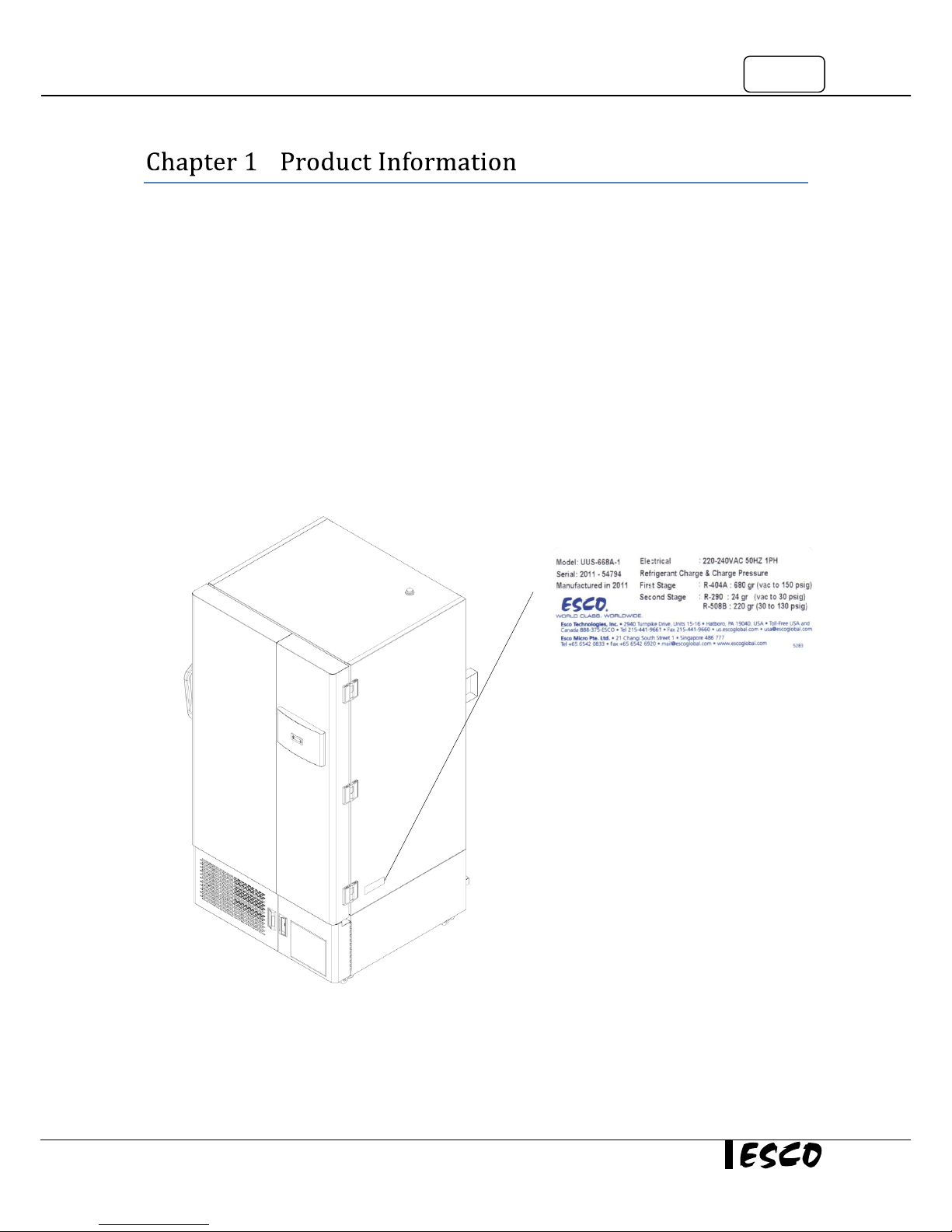
1.2 Labels
Model – model of the unit
Serial – the unit’s serial number
Manufactured in … - year of manufacture
Electrical – electrical requirement
Refrigerant Charge:
First Stage – amount, type and charge pressure of refrigerant
charging
Second Stage – amount, type and charge pressure of refrigerant
charging
Page 12
2
1.3 Quick View
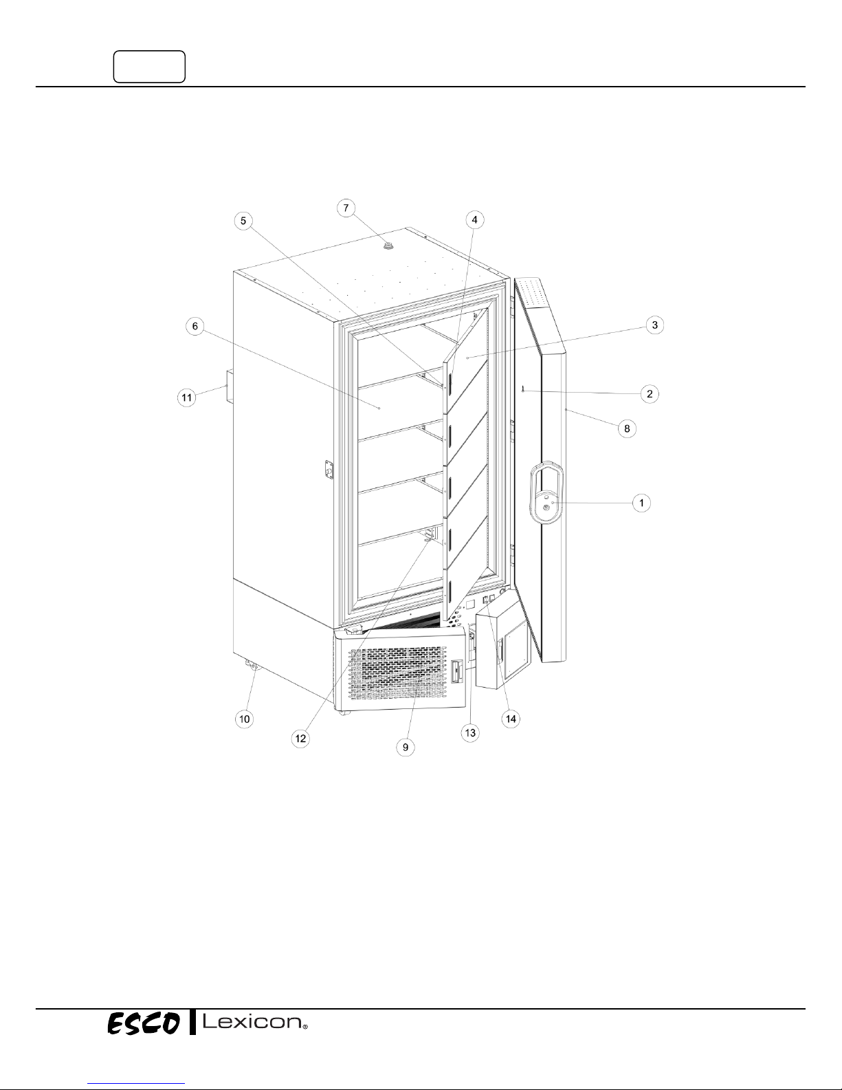
1.3.1 Front Quick View
1. Main Handle
2. Vacuum Relief
3. Inner Door
4. Embedded Pulls
5. Inner Doors Magnet
6. Shelves
7. Access Port
8. Control Panel
9. Air Vents / Intakes
10. Caster Wheel with Adjustable Foot
11. Cabinet Support
12. Control Probe
13. Power Failure (PF) Battery Location
14. PF Battery Disconnect Switch
Page 13
3
Ultra-Low Temperature Freezer
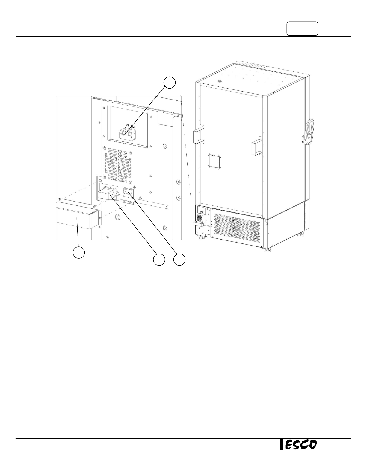
1.3.2 Back Quick View
1. Main Switch
2. Power Inlet
3. Remote Alarm Contact
4. Power Protection Bracket
1
2 3 4
Page 14

4
Page 15
5
Ultra-Low Temperature Freezer
–
2.1 General Requirement
2.1.1 Location Requirements
Install the unit on a firm and level floor in an indoor environment.
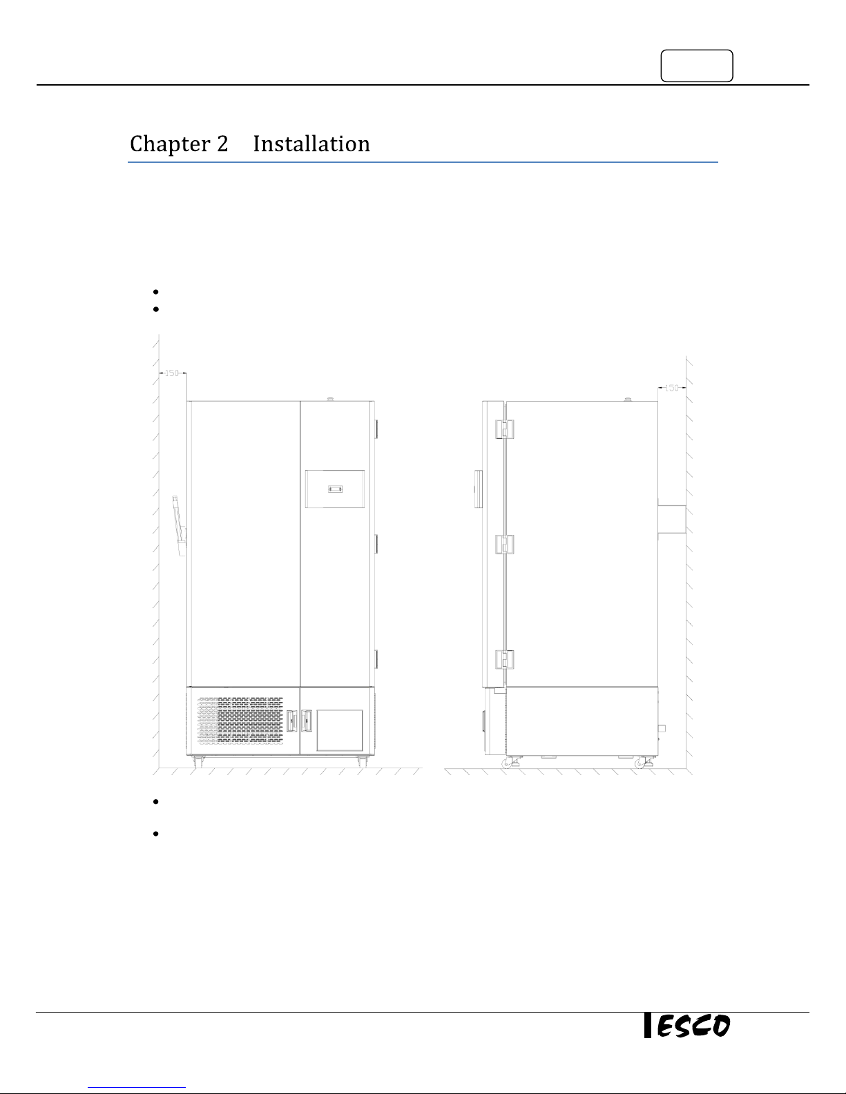
Allow at least 150 mm (6”) of open space on all sides from the sides, top and rear.
The location should be sufficiently ventilated so the heat from the unit can be removed from the area
to prevent any potential overheating condition of the ambient temperature.
Avoid installing a unit in an area with direct heat source such as sunlight, heat radiator, and other
heat sources.
Page 16
6
2.1.2 Environmental Requirements
Indoor use
Altitudes of up to 2000 meters (6600’)
Up to 90% relative humidity – non-condensing
Temperature between 15
O
C - 32OC (59OF - 90OF)
Note: Recommended operating temperature is 25oC (77oF).
Must be installed in room with sufficient ventilation. The room ventilation should be a technical
ventilation that is in accordance with the requirements of ZH 1/119 (Guidelines for laboratories) or
some other suited ventilation system with appropriate capacity.
2.1.3 Power Requirements
Designed for 230 VAC 50Hz 1Φ electrical rating
An unobstructed dedicated power outlet which is not shared with other appliances.
Installation Category: II
Note: Installation category (over voltage category) defines the level of transient over voltage which the
instrument is designed to withstand safely. It depends on the nature of the electricity supply and its over voltage
protection means. For example, in CAT II, which is the category used for instruments in installations supplied from
a supply comparable to public mains such as hospital and research laboratories and most industrial laboratories,
the expected transient over voltage is 2500 V for a 230 V supply and 1500 V for a 120 V supply.
Performance criteria B in voltage dips & short interruptions immunity test.
Note: During the voltage dips & short interruptions immunity test, flicker of the fluorescent light was observed
when the voltage dips and short interruption were being applied on the AC mains port of the equipment and selfrecovered after the test.
It is recommended that the voltage fluctuation doesn't exceed ±10% of the nominal voltage at all
times, or else an electrical power stabilizer can be installed.
UPS is recommended for better protection. If UPS is not used and there is a power failure, the
operator must take immediate action to prevent the danger of potential warm-up.
2.2 Installation
2.2.1 Unit Leveling
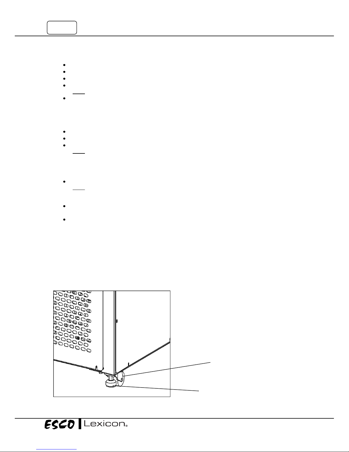
It is important that the equipment is properly leveled by positioning a bubble level on the middle shelf of the
freezer. The freezer has built in leveling feet for adjustment. To raise a corner with a leveling foot, use a cross
wrench to turn the leveling leg that appears to be in a low position in the counterclockwise direction.
Leveling feet
Caster Wheel
Page 17
7
Ultra-Low Temperature Freezer
2.2.2 Shelves Installation
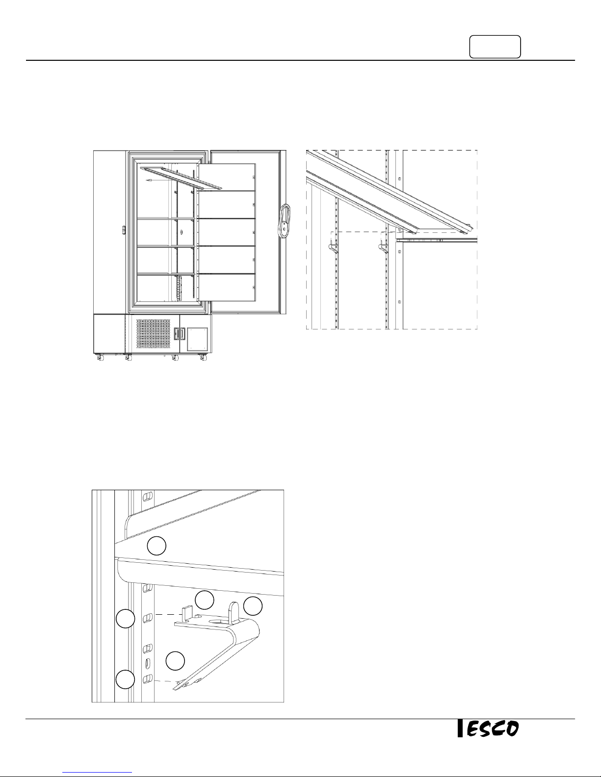
To change the position of the shelves, remove and re-install the pilaster clips (front and back) at desired shelf
level.
1. Open main door
2. Open all inner doors
3. Rotate shelf 45o vertically
4. Slide the shelf into the freezer chamber – on
top of the pilasters
5. Ensure the pilaster clips go through the holes
on the shelf
1. Put the first hook (1) into the pilaster hole
(4a)
2. Press upwards, then put the second hook
(2) into the pilaster hole (4b)
3. Install the shelf by aligning the third hook
(3) with the shelf hole - hole located
underneath the shelf (5)
1
2
3
4a
5
4b
Page 18
8
2.2.3 Omega Brackets Installation
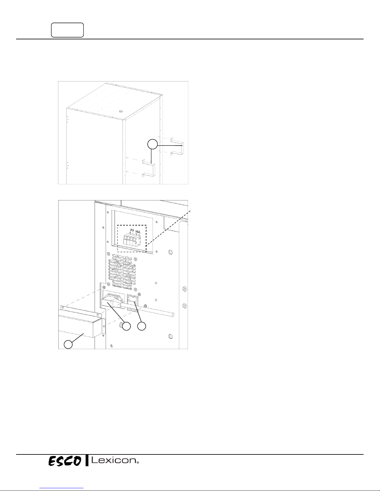
Omega brackets are used to ensure the required distance from the wall is maintained.
2.2.4 Remote Alarm Contacts Connection
External alarm can be connected to the remote alarm
contacts located at the back of the freezer base above
the power cord. These remote alarm contacts will
transmit a DC voltage upon occurrence of a high
temperature (HA) and power failure (PF) alarm. The
contacts provide 12 VDC (+) and (-) connectivity.
2.2.5 Electrical Supply Connection and
Power Protection Bracket Installation
Plug the power cord (1) into the power inlet at the
rear of the unit. Turn on the power switch (2). Install
the power protection bracket (3) over the power cord
and power switch by installing the 3 screws into the
pre-tapped holes.
1. Attach the bracket(1) to its place – sync the hole in
the bracket(1) to the hole in the unit
2. Screw the M6 bolts into the designated place (the
holes on top and below the bracket(1))
3. Repeat the 2 steps above with the other bracket(1)
1
2
1
3
Page 19
9
Ultra-Low Temperature Freezer
2.3 First Run (Also required whenever the freezer is turned off or moved)
Before activating the unit for the first time, ensure that there’s no object other than the shelves inside the
freezer.
Turn on the power switch. The controller will light up. The first stage compressor gets the power and starts
working. When the heat exchanger inside the freezer becomes cold enough and reaches a predetermined
temperature, the second stage compressor starts. The unit continues to operate until it reaches the set
temperature.
Lexicon™ Ultra-Low Temperature freezers have an operating temperature of -50 °C to -86 °C, depending on
the ambient temperature. The freezer is shipped from the factory with a temperature set point of -80 °C. Refer
to section 3.2 to change temperature setting.
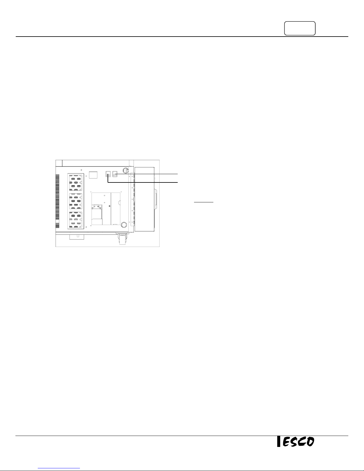
ULTF S-series controller has 2 switches for alarms located behind the right bottom door.
Once the unit reaches set point temperature, open the outer and the inner doors to load in half of the racks.
In the process of doing so, the freezer temperature is expected to warm up. Let the unit recover to the set
temperature then load in the rest of the racks.
If the freezer does not require any racks, let the unit run at set point for at least 48 hours for observation
before placing any products inside the unit.
2.4 Disclaimer
The performance and safety of the freezer, while rigorously evaluated at the factory, cannot be guaranteed
after transit and installation. Therefore the on-site testing is always recommended.
Power failure alarm
High temperature alarm
Power failure switch should always be turned on when the
unit runs. (Warning: Make sure the scheduled maintenance for
PF battery is carried out; refer to chapter 4, to ensure the battery
stays charged when the unit is on).
On the other hand, high temperature alarm switch should
remain off during initial start-up run in order to avoid
nuisance alarm beeping during pull down. It should only be
turned on once the unit has reached the temperature set
point.
Page 20

10
Page 21
11
Ultra-Low Temperature Freezer
-
3.1 Freezer Control System
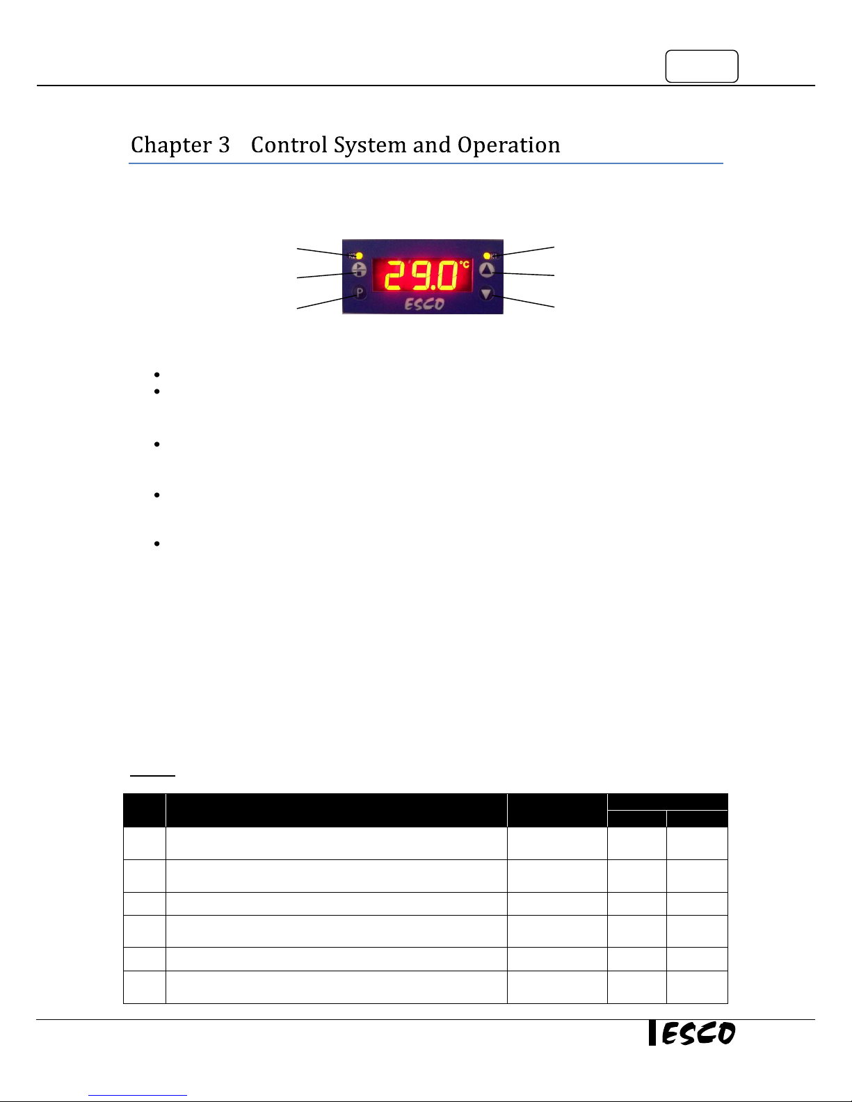
LED K1, K2
LED K2 lit up when respective relay connected to high/low temperature alarm energized
LED K1 lit up when the respective relay connected to 1
st
stage compressor energized
START/STOP Button
To start/stop the freezer operation
PROGRAMMING (P) button
To set up freezer’s programming
UP and DOWN button
To increase or decrease a value in the menu options
3.2 Temperature Offset Calibration
The control probe may need to be calibrated once the unit has passed the stabilization period. A good
laboratory practice would require at least annual calibration check.
Calibrating the Control Probe
Place a calibrated temperature recording instrument next to the PT100 sensor located inside the sensor cover
at the bottom right corner of the cabinet. Allow the freezer to stabilize for at least 2 hours if the unit has been
in service or at least 12 hours if the freezer is being started up for the first time. Compare the calibrated
temperature reading to the freezer display temperature. The offset value is determined by the difference
between the two readings.
Warning: It is imperative that only properly calibrated reference instruments should be used for calibration
Step
Action
Press
Display Show
First
Second
1
Press “P” key for 3 seconds (the second display shows
chamber temperature; eg: 15oC)
P
15
2
Set code 72 for accessing the parameter level by using the ▼
and ▲keys
▼and ▲
72
3
Press “P” key until offset
P
4
Set the offset value by using the ▼ and ▲keys (the second
display shows offset point; eg: 0oC)
▼and ▲
0.0
6
Press “P” key to confirm
P
7
Allow some time for the instrument to switch back to the
process value display
K1 LED
UP button
DOWN button
K2 LED
START/STOP button
PROGRAMMING (P) button
Page 22
12
Temperature Stabilization Periods
- Startup – Allow 12 hours for the temperature in the cabinet to stabilize before proceeding with
calibration
- Already Operating – Allow at least 2 hours after the display reaches set point temperature to stabilize
before proceeding with calibration
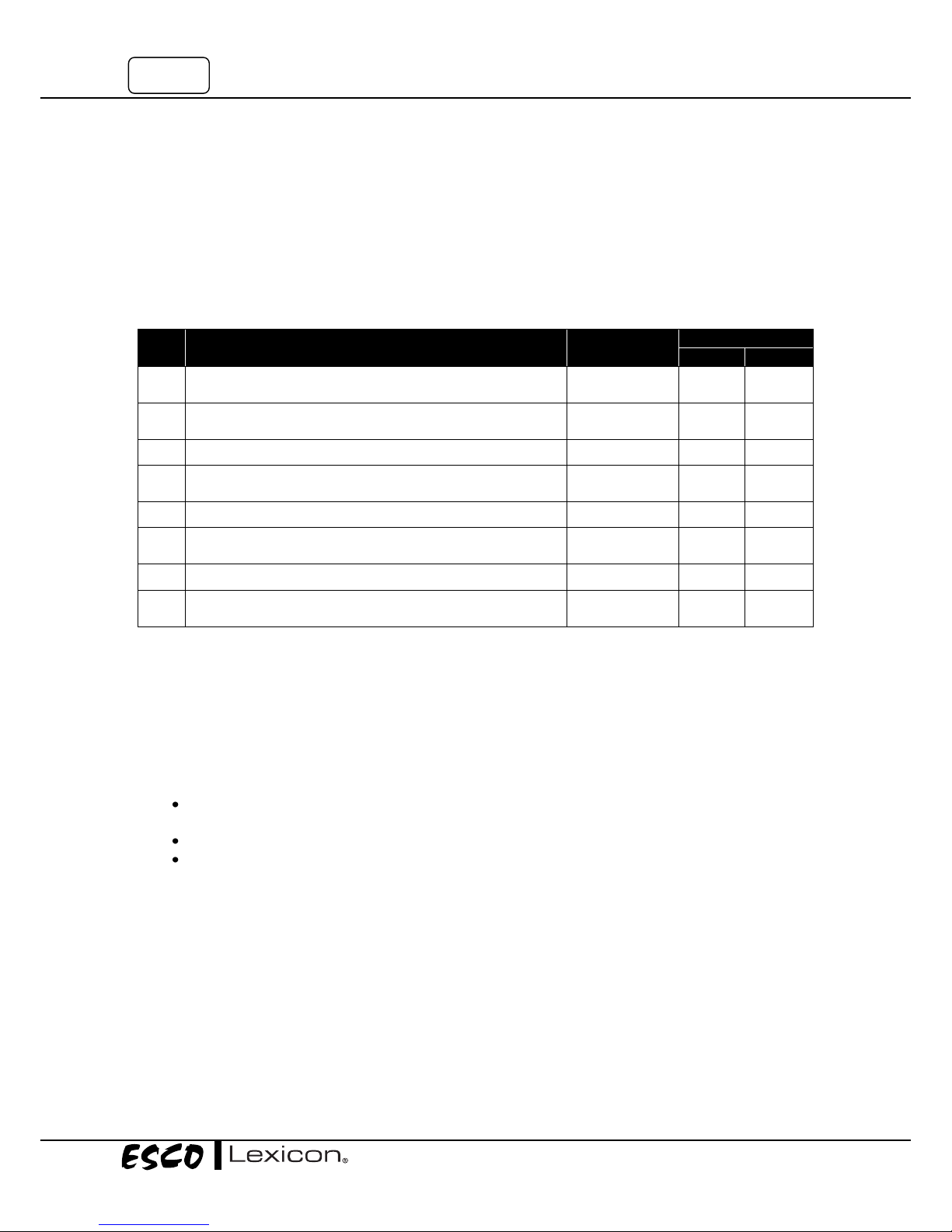
3.3 Set Temperature & Hysteresis
The freezer is shipped from factory with temperature set point -80oC and hysteresis 1oC. The LCD screen will
blink between the first and the second display
Step
Action
Press
Display Show
First
Second
1
Press “P” key for 3 seconds (the second display shows
chamber temperature; eg: 15oC)
P
15
2
Set code 72 for accessing the parameter level by using the ▼
and ▲keys
▼and ▲
72
3
Press “P” key to set the temperature
P
4
Set the temperature value by using the ▼ and ▲keys (the
second display show set point temperature; eg: -80oC)
▼and ▲
-80
Press “P” key to set the hysteresis
P
6
Set the hysteresis value by using the ▼ and ▲keys (the
second display show set point hysteresis; eg: 1oC)
▼and ▲
1
7
Press “P” key to confirm
P
8
Allow some time for the instrument to switch back to the
process value display
3.4 Operating the Freezer
3.4.1 Product Loading
Loading of warm product into the freezer should be done in batches. Do not fill the freezer with product of
more than 25 percent of the volume at one time as this process might introduce too much heat load into the
freezer. Allow freezer to stabilize. Once the temperature of the freezer returns to the set point, another batch
of product can be loaded in.
Fill an upright by starting at the bottom near the probe and add products to racks to one shelf at a
time, allow freezer to recover to set point or temperature between shelves
Fill empty shelves with frozen water jugs, for example, to help overall performance
Always make sure the vacuum relief port is free of frost and ice, to allow for timely re-opening of the
main door.
ESCO ULTs are designed for long term storage. It is recommended that only pre-frozen products be placed in
the unit as that will reduce the amount of heat load that must be absorbed by the freezer at one time.
3.4.2 Opening and Closing Doors
Main door and inners doors should be closed tightly at all times. When taking the samples out, open the main
door and then open only one inner door at a time.
Page 23
13
Ultra-Low Temperature Freezer
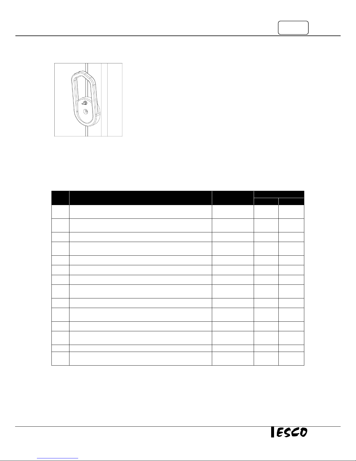
3.4.3 Locking the Main Door
Main door can be locked with the standard key set provided.
3.5 Alarm
3.5.1 High/Low Temperature Alarm
If ‘Set Point” is changed, the ‘Alarm High’ and ‘Alarm Low’ will also change. To modify the alarms:
Step
Action
Press
Display Show
First
Second
1
Press “P” key for 3 seconds (the second display shows
chamber temperature; eg: 15oC)
P
15
2
Set code 72 for accessing the parameter level by using the ▼
and ▲keys
▼and ▲
72
3
Press “P” key to set the temperature
P
4
Set the temperature value by using the ▼ and ▲keys (the
second display show set point temperature; eg: -80oC)
▼and ▲
-80
5
Press “P” key until r.2
P
6
Set the r.2 value by using the ▼ and ▲keys
▼and ▲
1
7
Press “P” key to set the Alarm Low
P
8
Set the Alarm Low value by using the ▼ and ▲keys (the
second display show temperature; eg: -90oC)
▼and ▲
-90
9
Press “P” key to set the Alarm High
P
10
Set the Alarm High value by using the ▼ and ▲keys (the
second display show temperature; eg: -70oC)
▼and ▲
-70
11
Press “P” key to set the hysteresis
P
12
Set the hysteresis value by using the ▼ and ▲keys (the
second display show set point hysteresis; eg: 1oC)
▼and ▲
1
13
Press “P” key to confirm
P
14
Allow some time for the instrument to switch back to the
process value display
3.5.2 Power Failure Alarm
Power failure switch should always be turned on when the unit runs. Refer to section 2.3 for details.
Page 24

14
Page 25
15
Ultra-Low Temperature Freezer
-
4.1 Scheduled Maintenance
Proper and timely maintenance is crucial for trouble free functioning of any device and your Esco ULTF is no
exception to this rule. We strongly recommend that you follow the maintenance schedule suggested
hereunder in order to obtain optimal performance from your Esco ULTF.
No.
Description of Task to Perform
Maintenance to be carried out every
1 Month
3 Month
6 Month
As Needed
1
Door gasket cleaning
√
2
PF battery checking
√
3
Air filter cleaning
√
4
Condenser cleaning
√
5
Vacuum relief port cleaning
√
6
General cleaning
√
7
Defrost and cleaning
√
8
Replace battery(s)
√
Above is the minimum frequency. More frequent maintenance is required depending on actual condition of the freezer.
4.2 General Cleaning
Routine cleaning of freezer should be carried out. The surfaces can be cleaned by wiping down with clean
water and a mild detergent using a sponge.
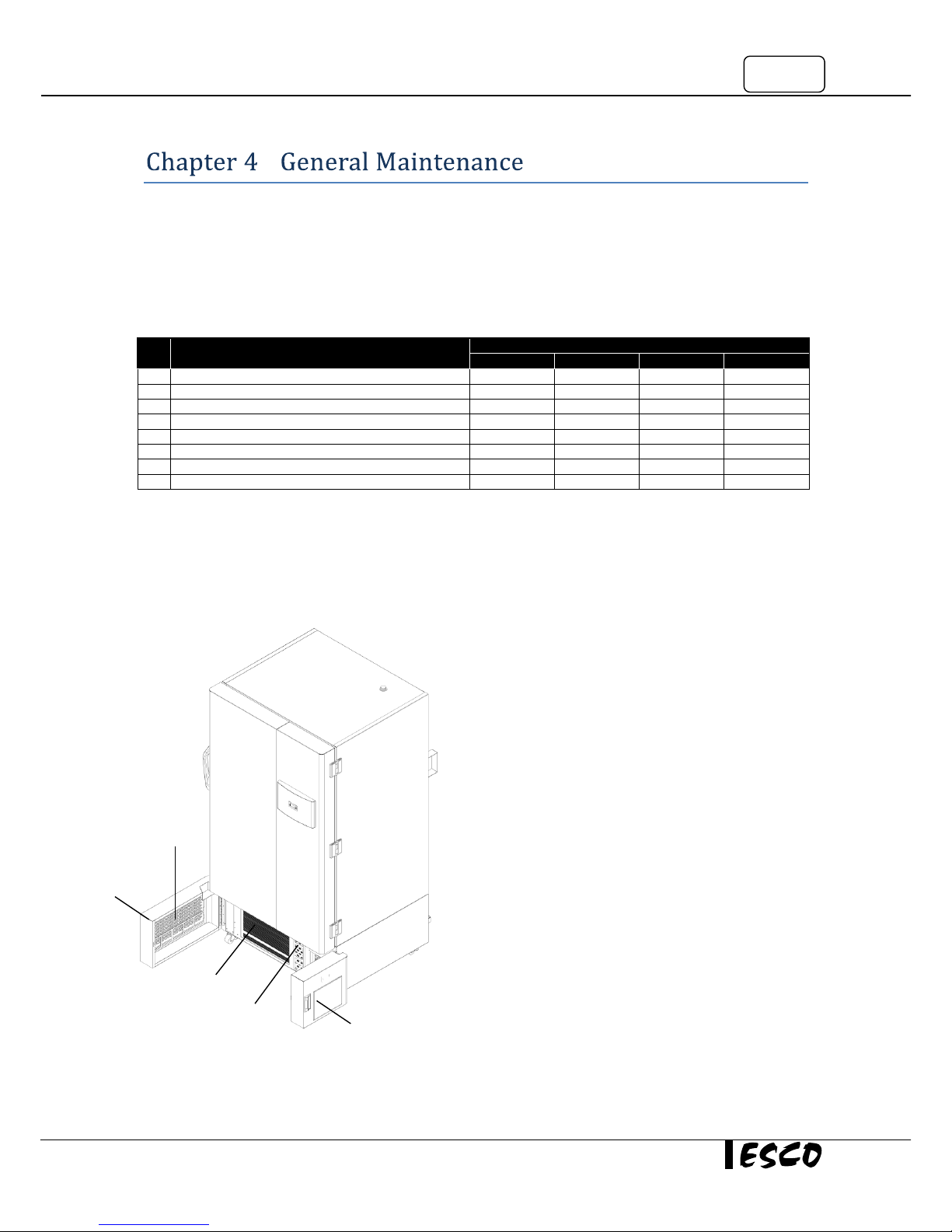
4.3 Condenser Cleaning
Cleaning the condenser is one of the most important tasks
to ensure the unit operates properly and efficiently. A
clogged condenser often results in poor performance and
raised power consumption. In some cases, clogged
condenser can choke the system’s air intake and cause
severe damage to the compressors.
To clean the condenser, pull open the left and right bottom
doors. Use a household type of vacuum cleaner to vacuum
the fins. Make sure you can clearly see through the fins
after the vacuum operation is completed.
The condenser should be cleaned once every 6 months or
more frequently if the area is dusty.
4.4 Air Filter Cleaning
The air filters are the first line of defense against dust and
dirt that might be pulled into the condenser. It is necessary
to inspect and clean the air filters on a regular basis.
To clean the air filter, open both left and right bottom
doors, there are two air filters installed. Remove the
condenser air filter, and wash it in water. Dry it out and
place it back in the air filter holders.
The air filter condition should be inspected and washed once in every 3 months. Replace the filter if it is too
dirty or worn out.
Air Filter1
Condenser
Air Filter2
Left Bottom Door
Right Bottom Door
Page 26

16
4.5 Door Gasket Cleaning
The door gasket is an important part to maintain and seal the freezer to achieve a proper temperature. Over
time, the gasket can get deformed or damaged if not properly kept clean from ice. To clean off the ice and
frost accumulating on the gasket, use a dull plastic scrapper to wipe off ice and frost accumulation that sticks
to the ice surface. Wipe off the water from the gasket before closing the door. Door gasket should be cleaned
at least monthly. More frequent cleaning may be required if dirt or excessive frost build-up prevents the door
from closing properly.
4.6 Vacuum Relief Port Cleaning
Use a soft cloth; remove any frost build-up from the vacuum relief port, located at the back of the main door
(See Quick View). Cleaning of vacuum relief port should be performed regularly, depending on how often and
how long the door is opened.
4.7 Defrost and Cleaning
The amount of frost accumulation in the freezer depends on how often and how long the door is opened. As
the frost gets thicker, the efficiency of the unit is adversely effected. The frost acts as an insulator as it slows
down the system’s ability to remove the heat from the freezer; this causes the unit to use more energy.
To remove the frost, move all products to another freezer that operates at the same temperature as the Esco
unit temporarily.
Turn off the power on the Esco unit, open the outer and inner doors to let the unit warm up. Place some
towels or other absorbent material around the freezer to absorb any melted frost that might run out. Once
the freezer is thawed, wipe off the condensation with a towel. Use a mixture of warm water and light
detergent to clean the interior and exterior of the unit carefully; do not let water drip into the refrigeration
and electrical compartments. Once cleaned, dry and power up the unit (see section 2.3 First Run).
4.8 PF Battery Checking
Locate the battery (see section 1.3 Quick View) and check its voltage output using a digital volt-meter. If the
voltage goes below 12 volts, replace the battery.
4.9 Preparing the Unit for Storage
Defrost and clean the unit as described in section 4.6 Vacuum Relief Port Cleaning. Turn off the battery power
switch. Turn off the freezer power switch. Disconnect power to battery(s) and to the freezer. The unit is ready
for storage.
4.10 Maintenance/Service Log
It is good practice (and in some cases regulatory requirement) to maintain a log of all maintenance work
carried out on your freezer.
Page 27
17
Ultra-Low Temperature Freezer
–
5.1 LCO2/LN2 Backup System
The backup system will keep the freezer chamber temperature below the critical level in the event of a power
or equipment failure. If power to the freezer fails, or the freezer warms above the user-defined set point, the
Backup System injects a controlled amount of liquid CO2 or N2 into the chamber to keep the chamber
temperature within the specified temperature range.
The LCO2 or LN2 must be injected from the access port located at the top side (back right corner) of the freezer.
The backup system probe should be installed side by side with control probe inside the cabinet.
For more information on the LCO2/LN2 backup system, please refer to the User Manual attached to the
accessory.
(Important Note: When selecting a LCO2 or LN2 supply cylinder, it must be equipped with a siphon tube)
5.2 Chart Recorder
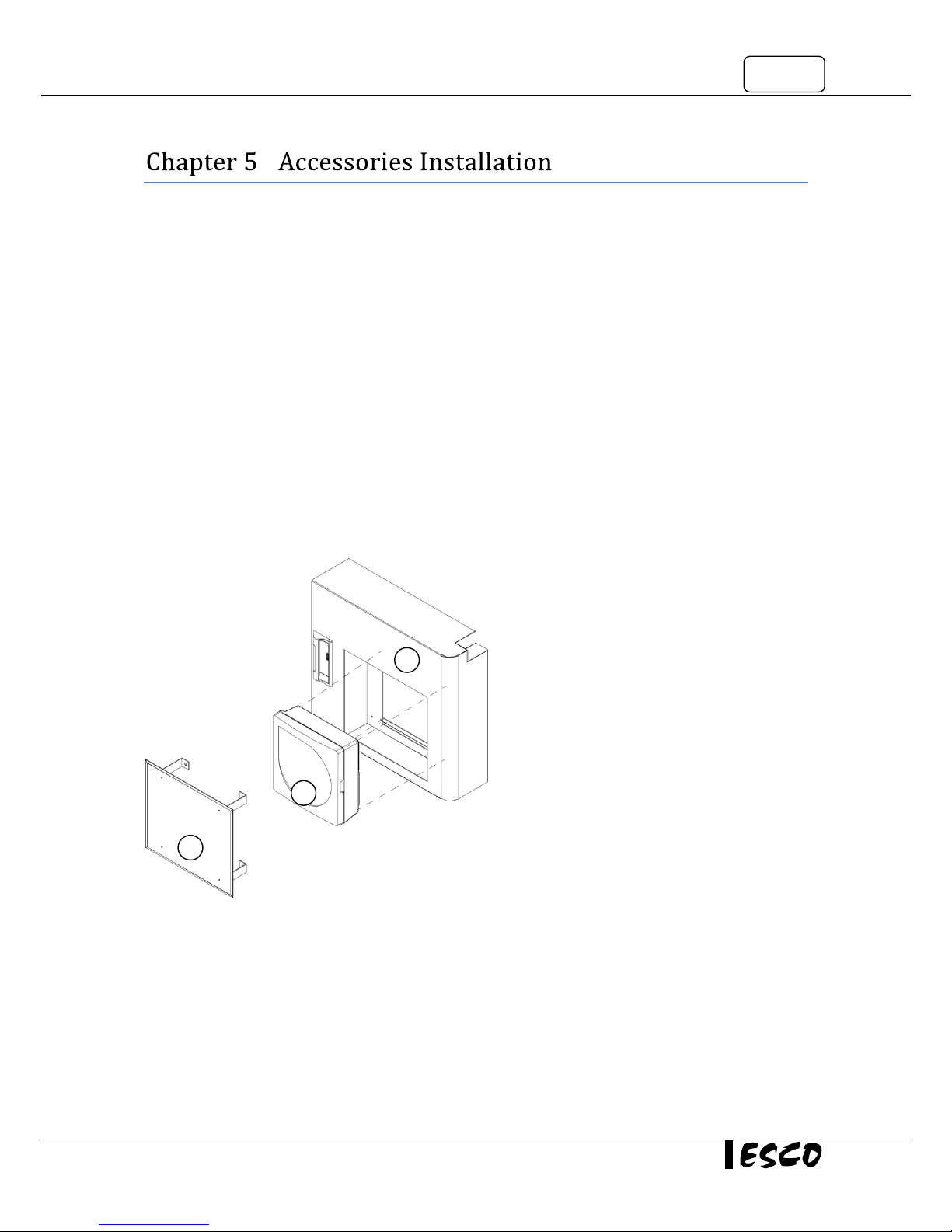
The chart recorder is used as an independent
temperature monitoring for the freezer.
To install the chart recorder into the Freezer:
Open the cover plate (1) on the right bottom door
and install 4 screws at the corners of chart
recorder (2) from the back of right bottom door
(3).
For more information on how to run and calibrate
the chart recorder, please refer to the chart
recorder User Manual attached to the accessory.
2 1 3
Page 28

18
Page 29
19
Ultra-Low Temperature Freezer
–
Under no circumstances should the unit be disassembled, repaired, or converted by unqualified people. Failure
to follow these instructions may cause personal injury and/or loss of property due to malfunctions, electric
shocks or fire.
Should the unit malfunction, stop the operation, and then pull out the power plug or turn off the power supply
at source. Continuing to operate the unit when it shows signs of malfunctioning may cause irreparable damage
to the freezer and/or its components.
The following troubleshooting guidelines address some of the basic problems that can be solved by the user or
operator. However if the problem persist, please contact your local distributor.
Problem
Possible Cause
The freezer does not work
(unit won’t cool down at all)
Ensure that the power cable firmly connects the unit to the main power supply
Ensure the fuse of the power cable is not blown
Ensure that the unit has been turned on
Ensure that the freezer’s main door is closed
The freezer shows poor performance
(unit won’t cool down fast enough)
Ensure the temperature is set correctly
Ensure the freezer is located correctly according to the location (section 2.1.1) and
environmental (section 2.1.2) requirement
Ensure that the products placed inside the freezer are pre-frozen. Products with
room temperature require the freezer to cool down and freeze the products first,
affecting the overall performance.
Ensure that the freezer is not overloaded
Ensure that the doors are not frequently open
The freezer generates unusual noise
Ensure the freezer is located correctly according to the location (section 2.1.1) and
environmental (section 2.1.2) requirement
Page 30

20
Page 31
21
Ultra-Low Temperature Freezer
–
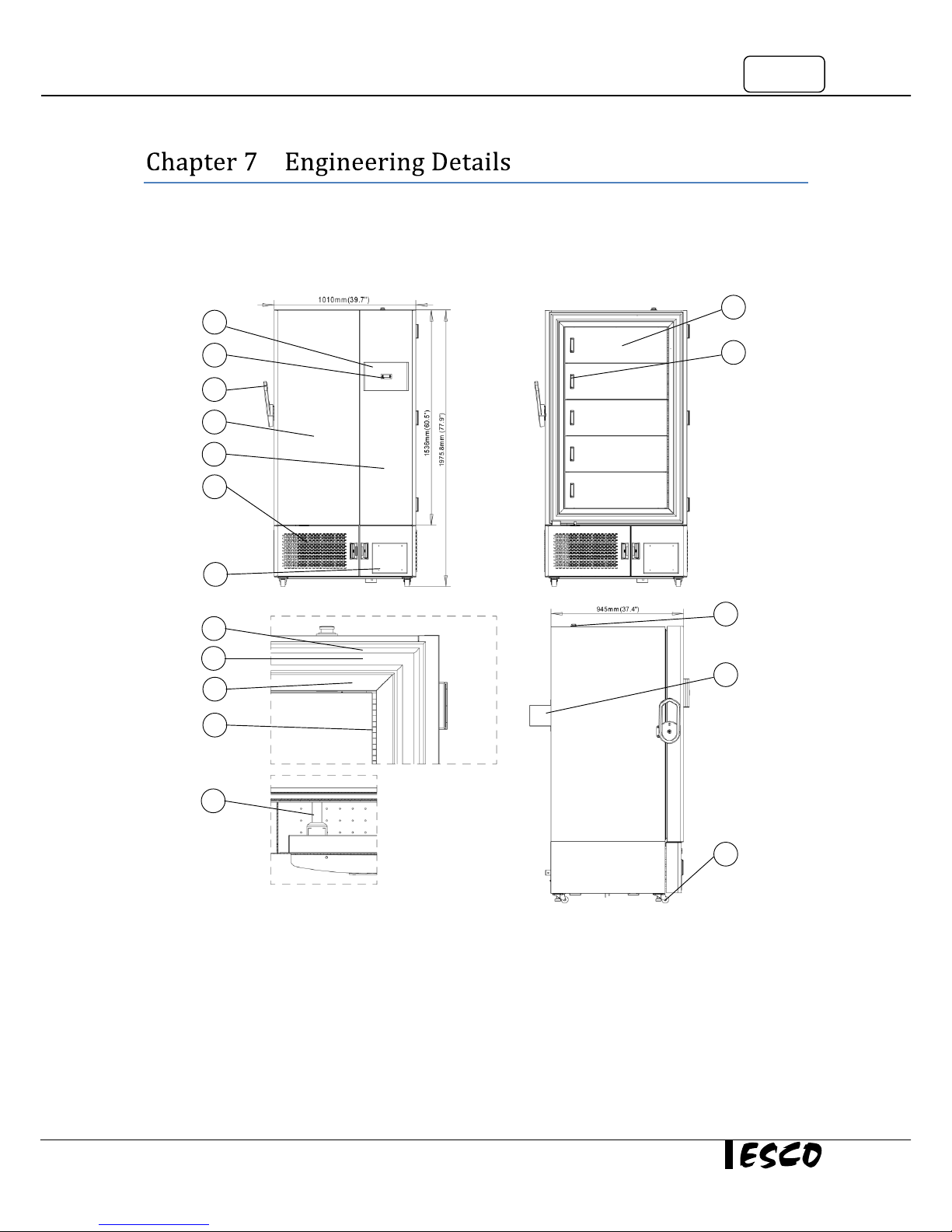
7.1 Engineering Drawing
1. PEP Cover
2. Temperature Controller
3. Door Handle
4. Main Door (White)
5. Main Door (Blue)
6. Condenser Grille
7. Chart Recorder Box
8. Thermal Break
9. Gasket
10. Stainless Steel Door Frame
11. Inner Door hinge
12. PEP
13. Inner Door
14. Embedded Pull
15. Access Port
16. Omega Bracket
17. Caster Wheel
1
2 3 4 5 6
7
8 9 10
11
12
13
14
15
16
17
Page 32
22
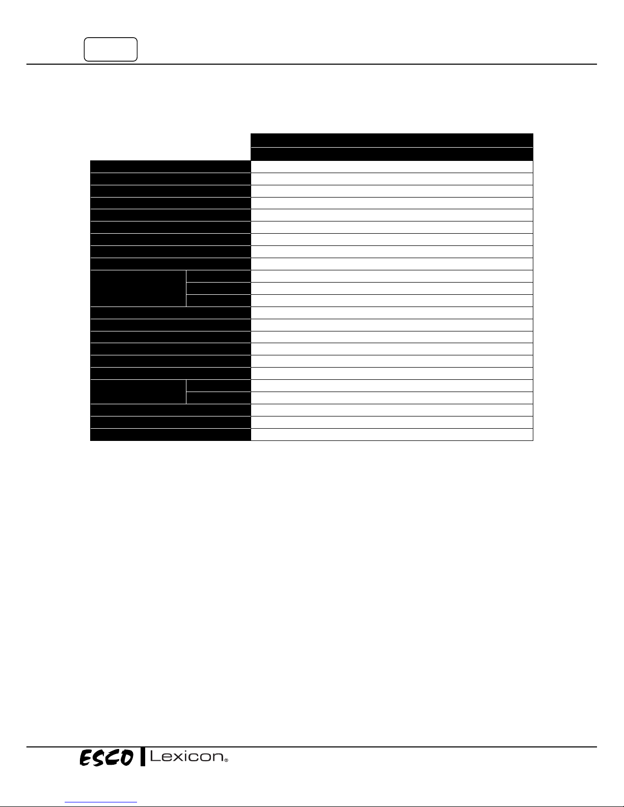
7.2 General Specifications
LEXICON™ ULTRA-LOW TEMPERATURE FREEZER
UUS-668A-1
Temperature Range
-50oC to -86oC
Ambient Temperature Range
15oC to 32oC (59oF to 89oF)
External Dimension (W x D x H)
1010 x 945 x 1980 mm (40.0” x 37.2” x 78.0”)
Internal Dimension (W x D X H)
750 x 685 x 1304 mm (30.0” x 27.0” x 51.0”)
Capacity
668.8 L (23.6 ft3)
Electrical Rating
230 V AC 50Hz 1Φ
Full Load Amps/Breaker
12A / 20A dedicated
Power Consumption
Approximately 14.2 KWh/day
Number of Outer/Inner Doors
1/5
Shelves
Material
Stainless Steel 304, adjustable, 4 Shelves
Size (W x D)
738x611 mm (28.9” x 25.1”)
Max Load
50 kg (110 lbs.)
Temperature Controller
Industrial digital controller
Access Port
Ø 25 mm (1”) - 1 port
Insulation Type
Polyurethane foam insulation
Refrigerant Type
Environmentally-friendly HFC refrigerants
Compressor
2 x hermetic 1.0 hp compressor
Condenser
Enhanced finned-tube, forced-air cooled condenser
Storage Box capacity
with Inventory Rack
2” Box
400
3” Box
300
Net Weight
326.5 kg (720 lbs.)
Shipping Weight
378 kg (833 lbs.)
Shipping Dimension
1152 x 1092 x 2160 mm (45.3” x 43.0” x 85.0”)
Page 33

APPENDIX
Page 34

Page 35
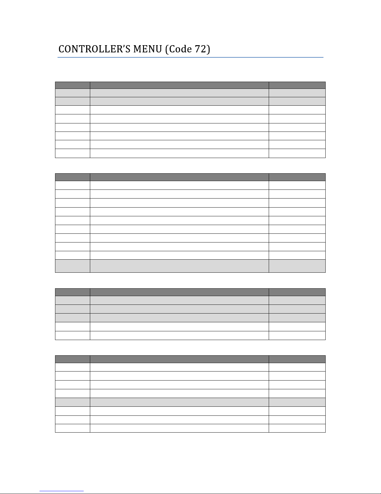
Controller
Parameter
Description
Value
Set point – target value
. ... .
Hysteresis
0.2 … 99.9
.
Low set point limit
.
High set point limit
Controller type
Switch on delay after power on
.
Minimum ON time (minimum time the unit is activated)
.
Minimum OFF time (minimum time the unit is deactivated)
Timer
Parameter
Description
Value
.
Defrosting/heating duration
.
Defrosting repeat cycle (only for controller)
.
Current remaining running time
.
Service interval
.
Service counter
.
Total operating hours
Temperature display during defrosting
.
Response after power-on
Enable start/stop key
.
Function of K-2 relay
0 – no function
1 – signal alarm active
Alarm
Parameter
Description
Value
.
Low alarm limit
-999 … +999
.
High alarm limit
-999 … +999
.
Alarm hysteresis
0.2 … 99.9
.
Alarm suppression time (delay)
.
Sensor over/under range response
Input
Parameter
Description
Value
Sensor
.
Start value for indication range with measurement input voltage or current
.
End value for indication range with measurement input voltage or current
.
Signal for measurement input current
.
Process value offset (for calibration)
-99.9 … 99.9
.
Lead compensation resistance
Unit
Filter time constant
Note: Only the highlighted parameters are used in this UUS product
Page 36

Page 37
Freezer
:
_______________________________________________________________
Serial Number
:
_______________________________________________________________
Person in Charge
:
_______________________________________________________________
1. This log record should be used by the operator to record any new agent that has been introduced to
the freezer during its operation, problems encountered, etc.
2. Please also record any major maintenance procedure performed by the service technician, for
example: parts replacement, recertification, etc.
Date
Event
User Signature
Supervisor Signature
In case of emergencies, please call:
Name
:
_______________________________________________________________
Cell Phone Number
:
_______________________________________________________________
E-mail
:
_______________________________________________________________
Page 38

 Loading...