

Esco KM35D EN, KM35D-S EN, KM35D EN VH, KM35D-S EN VH, KM35D EN TD Mounting And Operating Instruction
...Page 1
MBA: KM35D / 24V DC
012-000042E
Seite 1 von 13
Montage- und Betriebsanleitung
Kettenantriebe KM35D EN, KM35D-S EN
24 V DC
Mounting and operating instruction
chain motors KM35D EN, KM35D-S EN
24 V DC
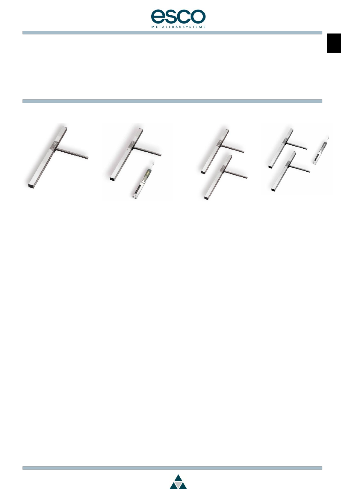
KM35D EN
KM35D-S EN
KM35D EN VH
KM35D-S EN VH
KM35D EN TD
KM35D-S EN TD
KM35D EN TD-VH
KM35D-S EN TD-VH
1 Inhaltsverzeichnis
1 Inhaltsverzeichnis ............................................... 1
2 Allgemeine Angaben ........................................ 2
Verwendete Symbole .................................................... 2
Grundlegende Hinweise ................................................ 2
Allgemeine Sicherheitshinweise ................................... 2
Bestimmungsgemäße Verwendung ............................ 3
Achtung bei Austausch ................................................. 3
Beschreibung des Antriebs ............................................ 3
3 Technische Daten für 1 Antrieb ........................ 4
4 Typenschild KM35 Antrieb ................................. 5
5 Abschaltströme VH-Antrieb .............................. 5
6 Montagevorbereitungen ................................... 6
7 Montage mechanisch ....................................... 6
8 Installation (elektrisch) ...................................... 7
9 Betrieb / Bedienung ........................................... 8
10 Wartung und Pflege ........................................... 8
11 Hilfe bei Störungen ............................................. 8
12 Demontage und Entsorgung ............................. 9
13 Gewährleistung und Kundendienst .................. 9
14 Anschlussplan .................................................. 11
15 Maßblatt ............................................................ 12
1 Contents
1 Contents .............................................................. 1
2 General information ........................................... 2
Symbols used ................................................................... 2
Basic instructions.............................................................. 2
General safety instructions ............................................ 2
Use for the Intended Purpose........................................ 3
Please note in case of replacement ........................... 3
Description of the motor ................................................ 3
3 Technical data for 1 motor ................................ 4
4 KM35 chain drive type plate ............................. 5
5 Breaking current VH-device ............................. 5
6 Preparing for assembly ...................................... 6
7 Assembly (mech.) .............................................. 6
8 Installation (elec.) .............................................. 7
9 Operation / control ............................................ 8
10 Maintenance and care ..................................... 8
11 Troubleshooting .................................................. 8
12 Dismantling and disposal .................................. 9
13 Warranty and customer service ....................... 9
14 Connection diagram ....................................... 11
15 Dimension sheet ............................................... 12
Trotz größtmöglicher Sorgfalt kann für den Inhalt dieser
Druckschrift keine Haftung übernommen werden.
Alle angegebenen Informationen sind keine zugesicherten
Eigenschaften im Sinne des § 434 BGB.
Although this document has been compiled with the
greatest possible care, we are unable to accept any liability
for its contents.
The information provided does not constitute a guaranteed
specification in the sense of article 434 of the German Civil
Code (§ 434 BGB).
D
GB
Page 2
MBA: KM35D / 24V DC
012-000042E
Seite 2 von 13
2 Allgemeine Angaben
Verwendete Symbole
Symbol
Signalwort
Bedeutung
Gefahr
Warnung vor Gefahrenquellen
Hinweis
Besondere Funktionen oder
Anwendungstipps
✓
Handlungsaufforderung
Grundlegende Hinweise
Die Montage- und Betriebsanleitung ist wichtiger Bestandteil der
Lieferung und ist an die Personen gerichtet, die den Antrieb
montieren, betreiben oder warten. Die Anleitung enthält
Informationen über das Produkt und seine sichere Verwendung.
Bitte lesen Sie die Anleitung sorgfältig durch und beachten Sie
insbesondere alle Hinweise, die die Sicherheit betreffen.
Bewahren Sie die Anleitung auf.
Bei unsachgemäß durchgeführter Montage und Installation
übernimmt esco keine Haftung.
Allgemeine Sicherheitshinweise
Beachten Sie unbedingt die folgenden Sicherheitshinweise.
Zusätzliche Hinweise in den weiteren Kapiteln sind durch die oben
beschriebenen Symbole auffällig gekennzeichnet.
Lassen Sie die Montage, Installation und Erstinbetriebnahme nur von
geschulten, sachkundigen Personen durchführen.
Beachten Sie alle für den Einsatzort geltenden Regeln und
Bestimmungen, wie z.B.
- Arbeitsschutzvorschriften
- Unfallverhütungsvorschriften
- VDE-Bestimmungen, DIN- und EN- Normen
- „Richtlinie für kraftbetätigte Fenster, Türen und Tore“, BGR 232
(bisher ZH-1/4.94) der Berufsgenossenschaft
(bei Bedarf bitte bei Fa. esco anfordern)
- „Merkblatt KB.01: Kraftbetätigte Fenster“ des Verbandes der
Fenster- und Fassadenhersteller (VFF) (bei Bedarf bitte bei Fa.
esco anfordern)
Verwenden Sie den Antrieb nur in technisch einwandfreiem Zustand,
bestimmungsgemäß, sicherheits- und gefahrenbewusst, unter
Beachtung der Montage- und Betriebsanleitung.
Bringen Sie Sicherheitseinrichtungen, wie z.B. Fangvorrichtungen
oder Sicherheitsscheren sachgerecht an und stellen Sie sicher, dass
diese funktionsfähig sind.
Die Verarbeitungsrichtlinien der Profilhersteller sind zu beachten.
Verwenden Sie nur Original-Ersatzteile, Original-Zubehör und
Original-Befestigungsmaterial der Fa. esco.
2 General information
Symbols used
Symbol
Keyword
Significance
Danger
Possible cause of risk warning.
Tip
Special functions or user tips
✓
Required action
Basic instructions
This assembly and user guide is an important part of the
delivery and is aimed at those personnel who will be fitting,
operating or servicing the machine. The instructions include
information about the product and its safe use.
Please read through this guide carefully and take particular note of
all instructions relating to safety.
Keep the guide in a safe place.
esco accepts no liability for incorrect assembly and installation.
General safety instructions
You must follow all the following safety instructions.
Additional instructions in later sections are clearly identified with the
symbols described above.
Assembly, installation and initial commissioning must be carried out
by trained, qualified personnel.
You are required to comply with all rules and regulations applying to
the installation location.
- Occupational safety regulations
- Accident prevention directives
- VDE regulations, DIN- and EN-standards
- “Richtlinie für kraftbetätigte Fenster, Türen und Tore” (Guidelines
for power-operated windows, doors and shutters), BGR232 (former
ZH-1/4.94) from the Employer’s Liability Association (can be
obtained from esco on request
- Instruction sheet “KB.01: Powered windows“ from the window and
awning manufacturer’s association (VFF) (can be obtained from
esco request)
Use this motor only if it is in full working order, with due regard to
correct use, safety and hazards and adhere to the instructions in this
assembly and operating instructions manual.
Attach all safety equipment, e.g. safety brakes, safety clamps
correctly and make sure these are working correctly.
The processing instructions of the profile manufacturers have to be
kept.
Use only original spare parts, original accessories or original
fastenings from esco.
Page 3
MBA: KM35D / 24V DC
012-000042E
Seite 3 von 13
Bestimmungsgemäße Verwendung
Der Kettenantrieb esco KM35D EN, KM35D-S EN ist
ausschließlich für das Öffnen und Schließen von Fenstern
vorgesehen.
Eine andere oder darüber hinaus gehende Verwendung gilt als
nicht bestimmungsgemäß.
Für Schäden, die durch andere Verwendung entstehen, haftet
Fa. esco nicht. Die Gewährleistung erlischt dadurch.
Achtung bei Austausch
Generell sollten Antriebsgarnituren, wenn möglich, komplett
getauscht werden, um eine optimale Funktion zu ermöglichen.
Bei Tandem- und Tripelgarnituren dürfen stets nur
versionsgleiche Antriebe kombiniert werden.
Use for the Intended Purpose
The esco KM35D EN, KM35D-S EN is designed exclusively for
opening and closing windows.
esco is not liable for damage caused by any other use. The
warranty will be voided in this event.
Any other use or additional use is classed as incorrect.
Please note in case of replacement
Generally all chain drive sets should be replaced completely as
a set to ensure proper function.
For Tandem and Triple sets, only chain drives of the same
software version may be combined.
Beschreibung des Antriebs
Der Kettenantrieb esco KM35D EN, KM35D-S EN ist zum
Einsatz in Gebäuden bestimmt.
Der Einbau kann sowohl in horizontaler als auch in vertikaler
Lage erfolgen.
Der Antrieb ist umsteuerbar.
Automatische Endabschaltung.
Öffnungsweite programmierbar.
Öffnungs- und Schließgeschwindigkeit programmierbar.
Dichtschluss über Zugkraft des Kettenantriebs. Reversieren
nach Erreichen der Endlage in Schließrichtung zur Schonung
der Flügeldichtung und Entlastung des Getriebes.
Geregeltes Anfahren durch Sanftanlauf.
Synchronisation von bis zu 4 Antrieben.
Ansteuerung über externe Schalter für Einzel- und
Gruppensteuerung.
Ein Umprogrammieren der Antriebe kann jederzeit auch im
eingebauten Zustand durch unsere Mitarbeiter vorgenommen
werden.
(Voraussetzung hierfür ist eine gut zugängliche Zuleitung)
Folgende Montagevarianten sind, abhängig von der
Profilgeometrie, möglich:
aufgesetzt auf dem Rahmen,
aufgesetzt auf dem Flügel,
verdeckt liegend im Blendrahmenprofil.
Hinweis
Zubehör sowie Befestigungsgarnituren, abhängig von
Montageart, Profilsystem und Profilmaterial entnehmen
Sie bitte dem esco Katalog Gruppe 10 oder der
Broschüre „Fensterantriebe und Zubehör“
Description of the motor
The esco KM35D EN, KM35D-S EN chain motor is designed for
use in buildings.
The motor can be installed either horizontally or vertically.
The motor is reversible.
Integrated electrical end-stop.
Programmable opening width.
Programmable Opening and Closing speed
Window tightness via pulling force of the motor.
Reversing function after reaching the end position in closing
direction to prolong the life of the weather seal and unload
the motor transmission.
Controlled start-up via soft start.
Synchronization up to 4 motors.
Controlled via external switches for single and group control.
The motors can be programmed also in mounted state by our
service personnel.
(Easily reachable connection cable required)
According to the profile geometry, there are several assembly
options as follows:
Mounted on the frame,
Mounted on the casement,
Concealed within the frame profile.
Tip
Please find accessories and fastener sets depending
on assembly type, profile system and profile material in
the esco catalogue category 10 or in the brochure
“Window drives and accessories”
Gefahr
Gefahr von Zerstörung des Antriebs
Die integrierte Elektronik stoppt den Antrieb beim
Öffnen und Schließen des Fensters an den zuvor
eingestellten Endlagen.
Zwischen den Endlagen ist eine Lastabschaltung aktiv.
Diese soll den Antrieb vor Überlastung schützen.
Verwenden Sie die Lastabschaltung keinesfalls als
reguläre Abschaltung.
Stellen Sie die Endlagen sorgfältig ein. Verwenden
Sie dazu das entsprechende Einstellgerät (siehe
Abschnitt 10: „Komponenten und Zubehör“)
Danger
Danger of irreparable damage to motor
The integrated electronic unit stops the motor when
opening and closing the window at the prespecified limit
points.
A load safety breaking is active between the limit stops.
This is designed to protect the motor from overload.
Do not use the load safety breaking to switch off the
motor regularly.
Adjust the limit stops with care
Use the correct adjustment device (see section
10:“components and accessories“)
Page 4
MBA: KM35D / 24V DC
012-000042E
Seite 4 von 13
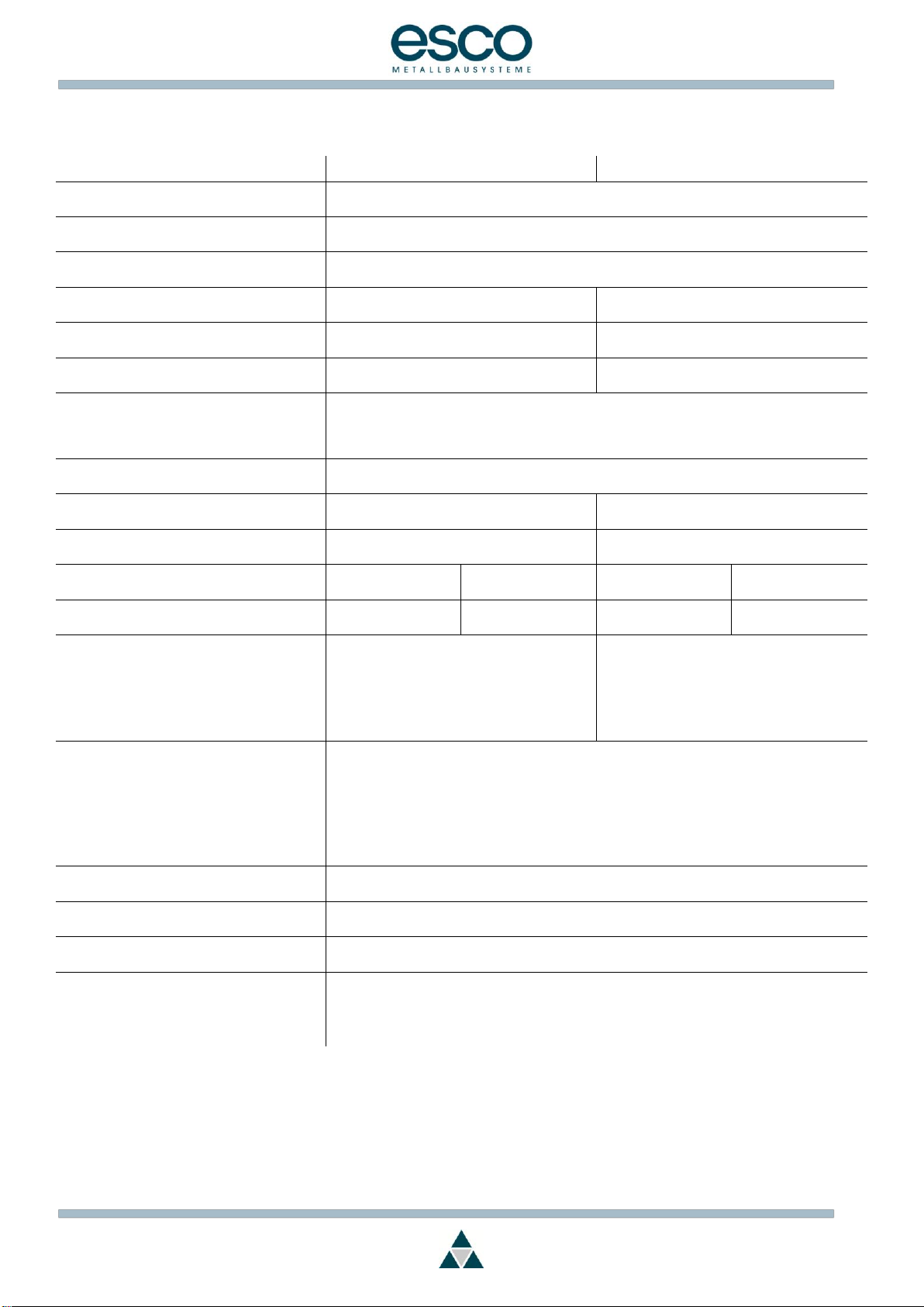
3 Technische Daten für 1 Antrieb
3 Technical data for 1 motor
Hub 300 / 500 mm
Hub 700 / 1000 mm
Nennspannung
nominal voltage
24 V DC
Betriebsspannung
operating voltage
22 – 40 V DC
Restwelligkeit max.
residual ripple max.
2,4 V p-p
Nennstromaufnahme
nominal current
0,95 A
1,5 A
Lastabschaltung
breaking current
1,2 A kurzzeitig / short-term
1,9 A kurzzeitig / short-term
Leistungsaufnahme
power consumption
23 W
34 W
Betriebsart / mode of operation
Kurzzeitbetrieb / short period operation
nach DIN EN 60034-1
according to EN 60034-1
S3 25%
S2 2 min
Zugkraft maximal zulässig
traction maximum permissible
350 N
Druckkraft maximal zulässig
pressure force maximum permissible
300 mm = 350 N
500 mm = 350 N
700 mm = 150 N
1000 mm = 80 N
Ausstellweite – programmierbar
opening width - programmable
20 – 300 mm
20 – 500 mm
20 – 700 mm
20 – 1000 mm
Öffnungsgeschwindigkeit Leerlauf max.
opening speed, no load max.
KM35D / D-S
10mm/s
KM35D / D-S
13mm/s
Schließgeschwindigkeit Leerlauf max.
closing speed, no load max.
KM35D
KM35D-S
10mm/s
≤ 5mm/s
KM35D
KM35D-S
13mm/s
≤ 5mm/s
Abmess. Gehäuse
dimensions housing:
Hub 300 mm / Travel 300 mm
Hub 500 mm / Travel 500 mm
Hub 700 mm / Travel 700 mm
Hub 1000 mm / Travel 1000 mm
30 x 35 x 562 mm
30 x 35 x 662 mm
30 x 35 x 762 mm
30 x 35 x 912 mm
Anschlusskabel
connection cable
Zwischen / Between
2 x 0,5 mm² und / and 2 x 1,5 mm²
Flexibel, Querschnitt entsprechend Leitungslänge /
flexible, wire cross section according to cable length
Anschlusskabel nicht im Lieferumfang des Antriebs enthalten /
connecting cable not included in delivery
Öffnungs- u. Schließvorgang
opening and closing operation
Umpolen der Betriebsspannung
pole reversal of operating voltage
Umgebungstemperatur
ambient temperature
-5 bis 50°C
(nicht kondensierend / non-condensing)
Schutzart
enclosure rating
IP 54, Spritzwasser geschützte Elektronik
IP 54, electronics protected from splashed water
Bemerkung
Note
Die Abschaltkraft ist technisch bedingt höher als die zulässige Nennkraft!
For technical reasons the breaking force is greater than the permissible rated force!
Die Laufzeiten können bei Synchronbetrieb abweichen.
Running time can differ in sychronic mode.
Page 5
MBA: KM35D / 24V DC
012-000042E
Seite 5 von 13
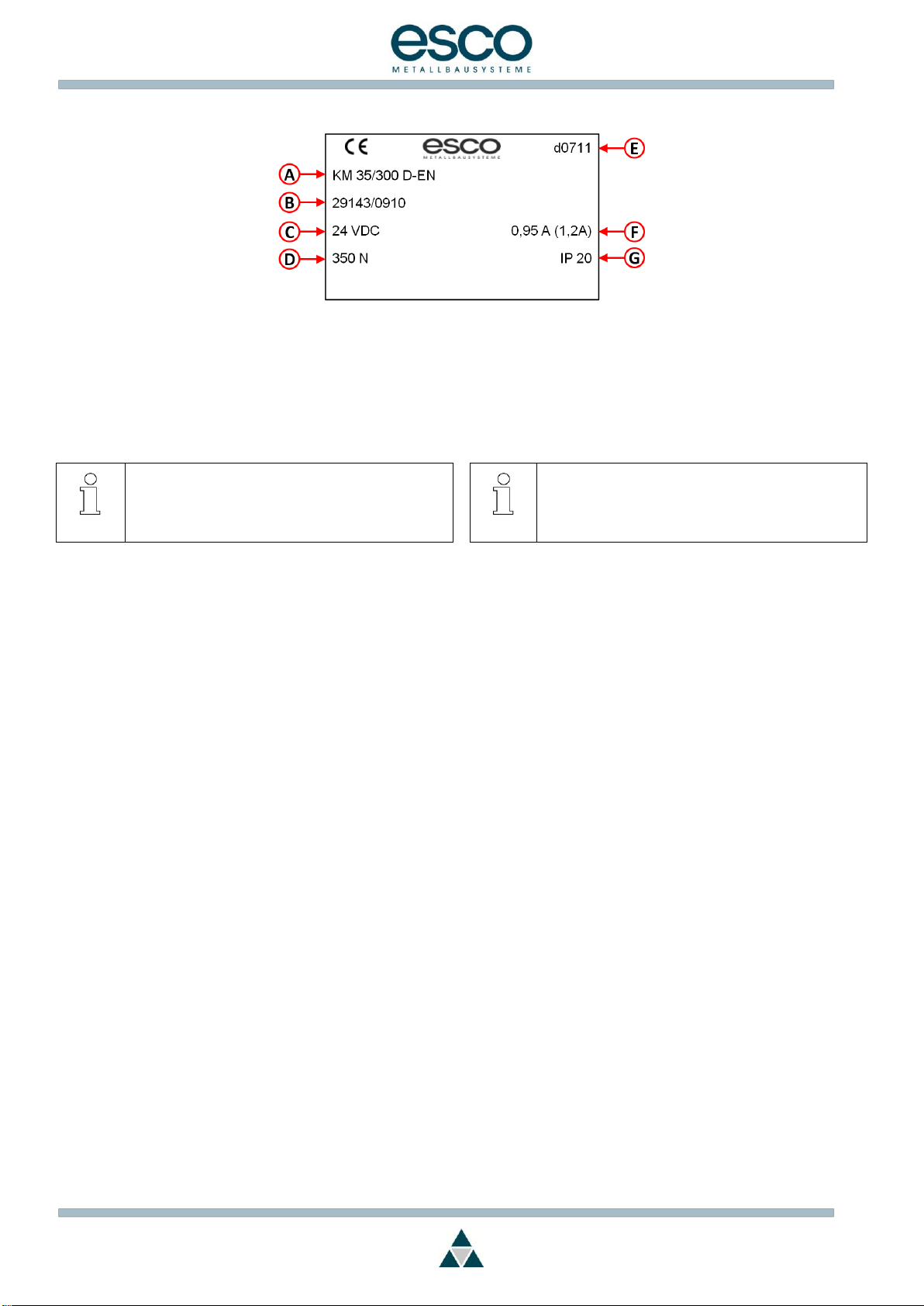
4 Typenschild KM35 Antrieb
4 KM35 chain drive type plate
A- Typenbezeichnung
B- Seriennummer / Produktionsdatum
C- Versorgungsspannung
D- Maximale Zugkraft
E- Software-Version (KW/JJ)
(Kalenderwoche/Jahr)
F- Nennstrom (Abschaltstrom)
G- IP Schutzklasse
Hinweis
Typenschild
Das Typenschild ist auf dem Antrieb angebracht.
Es ist in eingebautem Zustand nicht mehr zu erkennen.
A- Type designation
B- Serial number / date of production
C- Supply voltage
D- Max. pull force
E- Software-Version (cw/yy)
(calendar week/year)
F- Nominal current (breaking current)
G- IP protection class
Tip
Type plate
The type plate is attached to the motor.
It cannot be seen once the system is assembled.
5 Abschaltströme VH-Antrieb
Der VH-Antrieb hat keine eingebaute Lastabschaltung sondern
wird über die Elektronik des KM35D gesteuert. Daher ist es
wichtig, dass die korrekten Abschaltwerte im Programm des
KM35D eingestellt sind. Verwenden Sie für notwendige
Einstellarbeiten am Antrieb immer das esco Prüf-und
Einstellgerät (72-883042).
Bei allen ab Werk gelieferten Antriebsgarnituren sind die
Abschaltwerte korrekt eingestellt.
Bei Verwendung des Kettenantriebs mit VH Antrieben der
Generation T1, T2 oder bei Verwendung von neuen VH
Antrieben mit KM35D vor der Version d2212 gelten folgende
Hinweise.
Austausch, nur Kettenantrieb
Bei Verwendung des Kettenantriebs als Austauschantrieb mit
einem VH-Antrieb mit der Artikelnummer 72-722553 (T1) oder
72-533912 (T2) muss der Abschaltstrom auf 0,4 A programmiert
werden. Wenn die genannten Antriebe / Artikelnummern mit
dem im KM voreingestellten Abschaltstrom von 0,8 A betrieben
werden, ist eine Schädigung von Motor und Getriebe die Folge.
Austausch, nur VH-Antrieb
Der VH-Antrieb T3 ist nur verwendbar mit dem KM35D ab
Version d0711. Bei Verwendung des VH-Antriebs als
Reparatur/Ersatzantrieb mit KM35D vor der Version d2212
muss der Abschaltstrom im Kettenantrieb auf 0,8 A
programmiert werden.
5 Breaking current VH-device
The VH-device has no integral load interruption. It is operated
by the chain drive. Therefore it is important to adjust the correct
interruption values in the chain drive software. Always use the
esco Testing- and adjusting-device (72-883042) for necessary
adjustments of the chain-drive.
For all chain-drive-sets, supplied ex works, all breaking current
values are preset properly.
Consider the following notices when using the chain-drive with
VH-devices of the generation T1, T2 or new VH-devices with
KM35D prior to the software version d2212.
Replacement, chain drive only
Using the chain drive as replacement-drive in combination with
a VH-device 72-722553 (T1) or 72-533912 (T2) the breaking
current has to be set to 0.4 A.
If the VH-devices T1 or T2 are operated with a higher breaking
current than 0.4 A the motor or the gear will be damaged.
Replacement, VH-device only
The VH-device 72-638048 (T3) can only be operated with a
KM35D having a software-version as of d0711. When operated
with a KM35D with a software-version prior to version d2212 the
breaking current has to be set to 0.8 A.
Page 6

MBA: KM35D / 24V DC
012-000042E
Seite 6 von 13
6 Montagevorbereitungen
Gefahr
Personen- und Sachschäden durch unsachgemäßen
Einsatz
Stellen Sie mit Hilfe des Typenschildes am Antrieb und
den in Abschnitt „2 Allgemeine Angaben“ aufgeführten
Technischen Daten sicher, dass Sie den für ihre
Einbausituation richtigen Antrieb vorliegen haben.
Untersuchen Sie die Lieferung sofort nach Erhalt auf etwaige
Transportschäden. Bei Beschädigungen dürfen Sie den Antrieb nicht
montieren.
6 Preparing for assembly
Danger
Injury to persons and property due to incorrect
installation
Use the data plate on the motor and the technical data in
“2 General information“ to ensure that you have the
correct motor for your installation purposes.
Check the delivery immediately on receipt for damage caused in
transit. You must not install the motor if it is damaged.
7 Montage mechanisch
Gefahr
Gefahr
Nur geschulte, sachkundige Personen dürfen die
Montage vornehmen.
Gefahr
Quetschgefahr
Beim automatischen Öffnen oder - Schließen des
Fensters entstehen Zug- und Druckkräfte bis zu 400 N
je Antrieb. Diese Kräfte können beim Hineingreifen
zwischen Flügel und Rahmen Gliedmaßen
abquetschen. Insbesondere, da der Antrieb wiederholt
versucht den Hub zu beenden.
Greifen Sie nicht zwischen Flügel und Rahmen,
wenn der Antrieb läuft.
Sichern Sie bei einer Einbaulage des Fensterflügels
unter 2,50 m alle Quetsch- und Scherstellen gegen
unbeabsichtigtes Hineingreifen. Verfahren Sie dabei
gemäß „Merkblatt des VFF KB.01: Kraftbetätigte
Fenster“.
Gefahr
Verletzungsgefahr
Motorisch betätigte Kippfenster müssen Sie immer mit
einer Fangsicherung ausrüsten, um Verletzungen durch
herunterschlagende Fenster zu verhindern.
Auch bei der Montage am bereits eingebauten Fenster
können Sie sich durch plötzlich aufklappende
Fensterflügel verletzen.
Verwenden Sie geeignete Sicherheitseinrichtungen,
wie z.B. Sicherungsscheren als Fangsicherung.
Gefahr
Gefahr von Montagefehlern
Achten Sie bei der Montage der Beschlagteile
darauf, dass eine einwandfreie Funktion gegeben
ist.
Beachten Sie genau die beigefügten
Einbauzeichnungen.
✓
Bei einer drehbar gelagerten Montage des Antriebs
über die seitlichen Buchsen ist in jedem Fall die
entsprechende Abdeckhaube bzw. Versteifungsplatte
zur Aussteifung des Antriebs einzusetzen.
7 Assembly (mech.)
Danger
Danger
Assembly must be carried out by trained technicians.
Danger
Danger of crushing
Traction and pressure forces of up to 400 N for each
motor are produced when the window is opened or
closed automatically. These forces could cause limbs to
be crushed if persons reach between the window and
the frame. Particularly because the motor repeatedly
attempts to finish the stroke.
Do not reach between the window and the frame
when the motor is running.
For window installation openings of less than 2.50 m,
secure all crushing and shearing points against
inadvertent reaching. See information sheet VFF
KB.01: powered windows.
Danger
Risk of injury
Motorised bottom hung windows always require a safety
brake to prevent falling window from causing injuries.
If fitting to existing windows be aware that a sudden
opening of the window can cause injury.
Use appropriate safety equipment, e.g. a safety
clamp as a safety brake.
Danger
Danger from incorrect assembly
Make sure when attaching the fittings that these are
all operating correctly.
Read carefully through the installation drawings
provided.
✓
In case of a pivoted mounting of the motor via the lateral
bearings the corresponding covering hood or
reinforcement plate is necessary to support the motor.
Montieren Sie den Antrieb so, dass er jederzeit zugänglich ist.
Beachten Sie die Einbauzeichnung. Diese ist der
Befestigungsgarnitur beigepackt und enthält die entsprechenden
Maßangaben in Abhängigkeit von der Montageart und vom
Profilsystem.
Beachten Sie vor der Profilbearbeitung die folgenden Punkte:
- Mindestflügelbreite
- Mindestflügelhöhe
- maximales Flügelgewicht
- Platzbedarf am Profil unter Berücksichtigung der Montageart
Assemble the motor such that it is accessible at any time.
Read carefully through the installation drawing. It is packed with the
fittings kit and contains the measurement data relating to the type of
assembly and profile system.
Note the following points before cutting the profile:
- Minimum window width
- Minimum window height
- Maximum window weight
- Space requirement on profile taking into account the type of
assembly.
Page 7

MBA: KM35D / 24V DC
012-000042E
Seite 7 von 13
Kontrollieren Sie die erforderlichen Mindestabstände.
Führen Sie eine Funktionsprüfung durch.
Verwenden Sie dazu das passende esco Prüf - und Einstellgerät.
(siehe esco Katalog Gruppe 10 oder Broschüre „Fensterantriebe
und Zubehör“)
Bringen Sie den beigefügten Aufkleber
„Vorsicht Quetschgefahr!“ an.
8 Installation (elektrisch)
Gefahr
Gefahr eines elektrischen Schlages
Die bauseitige Elektroinstallation darf nur eine
zugelassene Elektrofachkraft vornehmen.
Schalten Sie alle stromführenden Teile frei, bevor Sie
Arbeiten an der Installation oder der Steuerung
ausführen.
Beachten Sie für die bauseitige Elektroinstallation die
VDE-Vorschriften und die Vorschriften des örtlichen
Netzbetreibers.
Gefahr
Quetsch- und Verletzungsgefahr
Beachten Sie die entsprechenden
Sicherheitshinweise
Durch ferngesteuert schließende Fenster oder durch
unbeabsichtigtes Betätigen der Steuerung kann es zu
Verletzungen kommen.
Treffen Sie entsprechende Maßnahmen gemäß
„Merkblatt des VFF KB.01: Kraftbetätigte Fenster“,
z.B. Sicherung der Schalter gegen unbeabsichtigtes
Einschalten.
Gefahr
Gefahr von Zerstörung des Antriebs
Der Antrieb benötigt einen 24 V DC-Anschluss. Andere
Spannungen zerstören den Antrieb.
Schließen Sie den Antrieb entsprechend an.
Verlegen Sie das Antriebs-Anschlusskabel nicht
zusammen mit einer Netzleitung.
Für den Anschluss des Antriebs ist ein zweiadriges flexibles
Anschlusskabel erforderlich
(siehe Kapitel 3„Technische Daten“).
Beachten Sie den elektrischen Anschlussplan in Kapitel 13
„Anschlussplan“.
Verwenden Sie Kabellängen, Kabelarten und Kabelquerschnitte
entsprechend den Angaben des Anschlussplans und den
„Technischen Daten“.
Stellen Sie sicher, dass die Kabel im Betrieb nicht abscheren,
abknicken oder sich verdrehen.
Check the required minimum distances
Check all functions.
Use the correct esco checking and adjusting device for this (see
esco catalogue category 10 or the brochure “Window drives and
accessories”).
Attach the “Danger, risk of crushing!” sticker provided.
8 Installation (elec.)
Danger
Danger of electric shock
The customer’s electrical installation must be carried out
by an authorised electrician.
Disconnect all live parts from the electricity supply
be- fore working on the installation or control of the
system.
Observe the VDE directives for the customer’s
electrical installation as well as those of the local
network operator.
Danger
Danger of crushing and injury
Follow the relevant safety instructions.
Remotely operated closing windows or inadvertent
actuation of the controller can cause injuries.
Apply measures according to information sheet VFF
KB.01: powered windows, i.e. secure the switches
against inadvertent actuation.
Danger
Danger of irreparable damage to motor
The motor requires a 24 V DC connection. Other
voltages will damage the motor.
Wire the motor accordingly.
Do not lay the motor connector cable alongside a
power cable.
The motor is connected with a two-core connector cable
(see chapter 3“Technical data”).
Follow the electrical wiring diagram in chapter 13 “Connection
diagram”
Use the cable lengths, types and cross sections specified in the
wiring diagram and “Technical data”.
Ensure that the cables cannot be sheared, kinked or twisted once in
operation
Page 8

MBA: KM35D / 24V DC
012-000042E
Seite 8 von 13
9 Betrieb / Bedienung
Gefahr
Quetschgefahr
Gefahr von Quetsch- und Scherstellen an den
Schließkanten des Fensters.
Beim automatischen Öffnen oder - Schließen des
Fensters entstehen Zug- und Druckkräfte bis zu 400 N.
Diese Kräfte können beim Hineingreifen zwischen Flügel
und Rahmen Gliedmaßen abquetschen. Insbesondere,
da der Antrieb wiederholt versucht den Hub zu beenden.
Halten Sie Kinder, behinderte Personen oder Tiere
von dem Fenster fern.
Greifen Sie nicht zwischen Flügel und Rahmen, wenn
der Antrieb läuft.
Informieren Sie sich über die Bedienung von
eventuell vorhandenen Schutzeinrichtungen.
Betrieb mit einem „Totmannschalter“
Bei Betrieb mit einer „Totmannschaltung“ (Tipp-
taster) muss eine Bestromung bis zum Ende des
Schließvorgangs erfolgen.
✓
Bei Einsatz eines Verriegelungsantriebs ist der
Kettenantrieb, nach dem Einfahren der Kette, noch
mindestens 20 Sekunden zu bestromen um das
Verriegeln des Beschlags zu gewährleisten.
9 Operation / control
Danger
Danger of crushing
Danger from crushing and sheering points on window’s
closing edges.
Traction and pressure forces of up to 400 N are
produced when the window is opened or closed
automatically. These forces could cause limbs to be
crushed if persons reach between the window and the
frame. Particularly because the motor repeatedly
attempts to finish the stroke.
Keep children, disabled persons and animals away
from the window.
Do not reach between the window and the frame
when the motor is running.
Familiarise yourself with the use of any necessary
safety equipment.
Operated by a “Dead man’s control”
If a “Dead man’s control” (push button) is used, the
button has to be pushed until the end of the closing
operation.
✓
If a locking motor is used the voltage supply needs to be
hold up min.20 seconds longer after the Chain has
retracted to ensure a correct locking of the fittings.
10 Wartung und Pflege
Um einen störungsfreien Betrieb zu gewährleisten, müssen Sie
die folgenden Arbeiten alle 1000 Öffnungszyklen durchführen:
Prüfen Sie alle Schrauben auf festen Sitz und ziehen Sie diese nach,
falls notwendig.
Kontrollieren Sie den optimalen Sitz des Fensterflügels im
Fensterrahmen. Justieren Sie die Befestigungsgarnitur
entsprechend.
Kontrollieren Sie alle Teile auf Beschädigungen und Verschleiß.
Tauschen Sie, falls erforderlich, die Teile aus.
Verwenden Sie keinesfalls Laugen oder Säuren zum Reinigen.
10 Maintenance and care
Carry out the following maintenance tasks every 1000 opening
cycles to ensure problem-free operation.
Check all screw fastenings are firmly seated and retighten if
necessary.
Check that the casement is sitting snugly in the frame. Adjust the
fittings accordingly.
Check all parts for damage and wear. Replace parts if necessary.
Never use alkaline or acid solutions to clean the windows.
11 Hilfe bei Störungen
Die Reparatur eines defekten Antriebs ist beim Weiterverarbeiter
oder beim Endanwender nicht sachgerecht möglich und daher nicht
zulässig. Eine Reparatur kann nur im Herstellerwerk durchgeführt
werden. Falls Sie den Antrieb öffnen oder ihn manipulieren erlischt
der Garantieanspruch.
Tauschen Sie daher einen defekten Antrieb aus und lassen Sie ihn
im Herstellerwerk reparieren.
Falls der Antrieb stehen bleibt, prüfen Sie bitte, ob die
Lastabschaltung aktiviert wurde.
Reagiert der Antrieb nicht auf die Bedienung des Schalters/ Tasters,
lassen Sie bitte die elektrische Versorgung durch eine Fachkraft
überprüfen.
11 Troubleshooting
A defective motor cannot actually be repaired by a fitter or end user
and this is therefore impermissible. Repairs must be carried out at
the manufacturer’s premises. The warranty is void in the event that
you open or tamper with the motor.
Therefore, replace defective motors and return them for repair to the
manufacturers premises.
If the motor stops please check whether the load safety breaking has
been triggered.
If the motor fails to respond when switched on, please have the
electricity supply checked by an electrician.
Page 9

MBA: KM35D / 24V DC
012-000042E
Seite 9 von 13
12 Demontage und Entsorgung
Demontage
Gefahr
Beachten Sie die Sicherheitshinweise!
Der Arbeitsablauf ist der gleiche, wie für die Montage
beschrieben, jedoch in umgekehrter Reihenfolge. Die
Einstellarbeiten entfallen.
Entsorgung
Hinweis
Antriebsbestandteile
Aluminium
Eisen
Kunststoff
Kupfer
Zink
Entsorgen Sie die Teile entsprechend den vor Ort gültigen
gesetzlichen Vorschriften.
12 Dismantling and disposal
Dismantling
Danger
Read through the safety instructions!
To disassemble, follow the assembly instructions in reverse
order. There are no adjustments to be made.
Disposal
Tip
Motor components
Aluminium
Iron
Plastic
Copper
Zinc
Disposal of parts according to local legal requirements.
13 Gewährleistung und
Kundendienst
Grundsätzlich gelten unsere „Allgemeinen
Geschäftsbedingungen“.
Die Gewährleistung entspricht den gesetzlichen Bestimmungen
und gilt für das Land, in dem der Antrieb erworben wurde.
Die Gewährleistung erstreckt sich auf Material- und
Fertigungsfehler, die bei einer normalen Beanspruchung
auftreten.
Gewährleistungs- und Haftungsansprüche bei Personen- und
Sachschäden sind ausgeschlossen, wenn sie auf eine oder
mehrere der folgenden Ursachen zurückzuführen sind:
Nicht bestimmungsgemäße Verwendung des Antriebs.
Unsachgemäße Montage, Inbetriebnahme, Bedienung,
Wartung und Reparatur des Antriebs.
Betreiben des Antriebs bei defekten, nicht ordnungsgemäß
angebrachten oder nicht funktionsfähigen Sicherheits- und
Schutzvorrichtungen.
Nichtbeachten der Hinweise in der Montage- und
Betriebsanleitung.
Eigenmächtige bauliche Veränderungen am Antrieb.
Katastrophenfälle durch Fremdkörpereinwirkung und höhere
Gewalt.
Verschleiß.
13 Warranty and
customer service
Our “General terms and conditions of business” apply in
principle.
The warranty complies with legal requirements and applies for
the country in which the motor was acquired.
The warranty covers material and manufacturing defects which
occur during normal use.
Guarantee claims and claims for liability in the case of personal
injury and material damage are excluded if they result from one
or more of the following causes:
Incorrect use of the motor.
Incorrect assembly, commissioning, operation and
maintenance and repair of the motor;
Operation of the motor with defective safety equipment or
with incorrectly attached or non-functioning safety or
protective equipment.
Non-observance of the instructions in this assembly and
operating instructions manual.
Unauthorized physical alterations to the motor.
Catastrophic incidents resulting from the effects of a foreign
body or force majeure.
Wear.
Page 10

MBA: KM35D / 24V DC
012-000042E
Seite 10 von 13
Ansprechpartner für eventuelle Gewährleistungen, oder wenn Sie Ersatzteile oder Zubehör benötigen, ist die für Sie zuständige
Niederlassung.
Please contact your nearest dealer with any warranty queries or if you require spare parts or accessories.
Niederlassungen esco Metallbausysteme / esco-Metallbausysteme branches:
Gebiet Nord/Northern region
esco Berlin
Am Jägerberg 3
+49 (0)3304 / 3995-0
16727 Velten
+49 (0)3304 / 3995-55
Gebiet Ost/Eastern region
esco Chemnitz
An der Wiesenmühle 11
+49 (0)371 / 81560-0
09224 Chemnitz
+49 (0)371 / 81560-69
esco Erfurt
Mielestrasse 3
+49 (0)36202 / 289-0
99334 Ichtershausen
+49 (0)36202 / 289-30
Gebiet Süd/Southern region
esco Ditzingen
Dieselstrasse 2
+49 (0)7156 / 3008-0
71254 Ditzingen
+49 (0)7156 / 3008-600
Gebiet West/Western region
esco Frankfurt
An den drei Hasen 22a
+49 (0)6171 / 20603-0
61440 Oberursel
+49 (0)6171 / 20603-99
info@esco-online.de
@
www.esco-online.de
Österreich/Austria
esco Metallbausysteme Austria GmbH
Gewerbestraße 14
+43 (0)6225 / 70030-0
A-5301 Eugendorf
+43 (0)6225 / 70030-26
Polen/Polskâ
esco Polska SP.z.o.o.
ul. Rzeczna 10
+48 (0)22 / 67925-22
PL-03794 Warszawa
+48 (0)22 / 67856-67
www.esco.com.pl
Page 11

MBA: KM35D / 24V DC
012-000042E
Seite 11 von 13
14 Anschlussplan
14 Connection diagram
Page 12

MBA: KM35D / 24V DC
012-000042E
Seite 12 von 13
15 Maßblatt
15 Dimension sheet
Page 13

MBA: KM35D / 24V DC
012-000042E
Seite 13 von 13
Page 14

Einbauerklärung: KM35D / KM35D-S
Einbauerklärung
Declaration of Incorporation
im Sinne der EG-Richtlinie 2006/42/EG über Maschinen (Anhang II B)
according to EC directive 2006/42/EC on machinery (Annex II B)
Name und Anschrift des Herstellers / Name and address of the manufacturer:
esco Metallbausysteme GmbH
Dieselstr. 2
D-71254 Ditzingen
Hiermit erklären wir, dass die nachstehend beschriebene unvollständige Maschine
Herewith we declare, that the partly completed machinery described below
Produktbezeichnung / product denomination:
Serien- / Typenbezeichnung / model/type:
Seriennummer, Baujahr / Serial number, Year of
manufacture:
Kettenantrieb
KM35D,KM 35D-S
siehe Typenschild / see identification plate
alle grundlegenden Anforderungen der Maschinenrichtlinie 2006/42/EG erfüllt, soweit es im Rahmen des Lieferumfangs möglich
ist. Ferner erklären wir, dass die speziellen technischen Unterlagen gemäß Anhang VII Teil B dieser Richtlinie erstellt wurden.
Die unvollständige Maschine entspricht zusätzlich den Bestimmungen der Richtlinie 2014/30/EU über elektromagnetische
Verträglichkeit. Die Schutzziele der Richtlinie 2014/35/EU über elektrische Betriebsmittel werden eingehalten.
is complying with all essential requirements of the Machinery Directive 2006/42/EC, as far as the scope of delivery allows.
Additional we declare that the relevant technical documentation is compiled in accordance with part B of Annex VII.
In addition the partly completed machinery is in conformity with the EC Directive 2014/30/EC relating to electromagnetic
compatibility. The safety objectives of the Directive 2014/35/EC relating to electrical equipment are observed.
Wir verpflichten uns, den Marktaufsichtsbehörden auf begründetes Verlangen die speziellen Unterlagen zu der unvollständigen
Maschine über unsere Dokumentationsabteilung zu übermitteln.
We commit to transmit, in response to a reasoned request by the market surveillance authorities, relevant documents on the
partly completed machinery by our documentation department.
Die unvollständige Maschine darf erst dann in Betrieb genommen werden, wenn ggf. festgestellt wurde, dass die Maschine oder
Anlage, in welche die unvollständige Maschine eingebaut werden soll, den Bestimmungen der Richtlinie 2006/42/EG über
Maschinen entspricht und die EG-Konformitätserklärung gemäß Anhang II A ausgestellt ist.
The partly completed machinery must not be put into service until the final machinery into which it is to be incorporated has been
declared in conformity with the provisions of Directive 2006/42/EC on Machinery, where appropriate, and until the EC Declaration
of Conformity according to Annex II A is issued..
Bevollmächtigter für die Zusammenstellung der relevanten technischen Unterlagen (EU-Adresse)
The person authorized to compile the relevant technical documentation (must be established within EU):
esco Metallbausysteme GmbH
Technologiezentrum
Dieselstr. 2
D-71254 Ditzingen
Ditzingen, 16.01.2012
Schill, Christoph Geschäftsführer
Ort, Datum
Place, Date
Name, Vorname und Funktion des Unterzeichners
surname, first name and function of signatory
Unterschrift
Signature
 Loading...