

Page 1
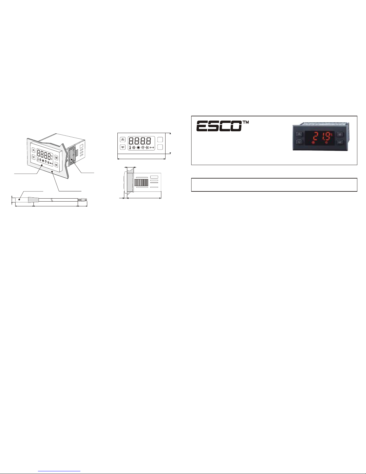
8. MOUNTING.
Controller should be placed in the panel in hole sized 71x29mm and fasten with mounting
terminals.
Mounting
terminals
Ip65
protection class
Panel surface
(maximum thickness
20mm)
9. INSTALLATION.
Controller meets the requirements for immunity to electromagnetic interference in an
industrial environment according to the following standards:
Electromagnetic compatibility (EMC):
–EN-61000 part 6-4 – requirements for emissivity in an industrial environment
–EN-61000 part 6-2 – requirements for immunity in an industrial environment
It also meets the safety requirements according to standard:
°C
°F
72
max 20
4,5
76
35
M
set
Controller meets the requirements for immunity to electromagnetic interference in an
industrial environment according to the following standards:
Electromagnetic compatibility (EMC):
–EN-61000 part 6-4 – requirements for emissivity in an industrial environment
–EN-61000 part 6-2 – requirements for immunity in an industrial environment
It also meets the safety requirements according to standard:
–EN-61000 part 1 – safety requirements for eletrical devices
Controller meets the requirements of EU directives No. 72/23/EEC; 93/68/EEC; 89/336EEC.
10. ADMISSIONS.
Ip67 protection
class
6
2000 2050
ES-30
COOLING CONTROLLER
Version 2.0
USER MANUAL / WARRANTY
Page 2
1. SPECIFICATIONS
Input:
Sampling period:
330 ms
230V~ ±15% or 12V=/~, max 3VA
Operation conditions: -5...60°C; 0...85%RH (non-condensing)
Storage conditions: -40...85°C; 0...85%RH (non-condensing)
Power supply:
2 temperature sensors: NTC 5k by 25°C
bistate input (normally opened or normally closed)
Measuring accuracy: ±0,5%
Resolution: 0,1°C in whole range
Control form:
ON-OFF with hysteresis
Display:
LED, 4 digits, 11mm height with graphic icons
Degree and protection class:
IP65 / II
Measuring range: -50...+150°C
Attention! The total current charged by the device can not exceed 12A.
2. OUTPUTS CARRYING CAPACITY
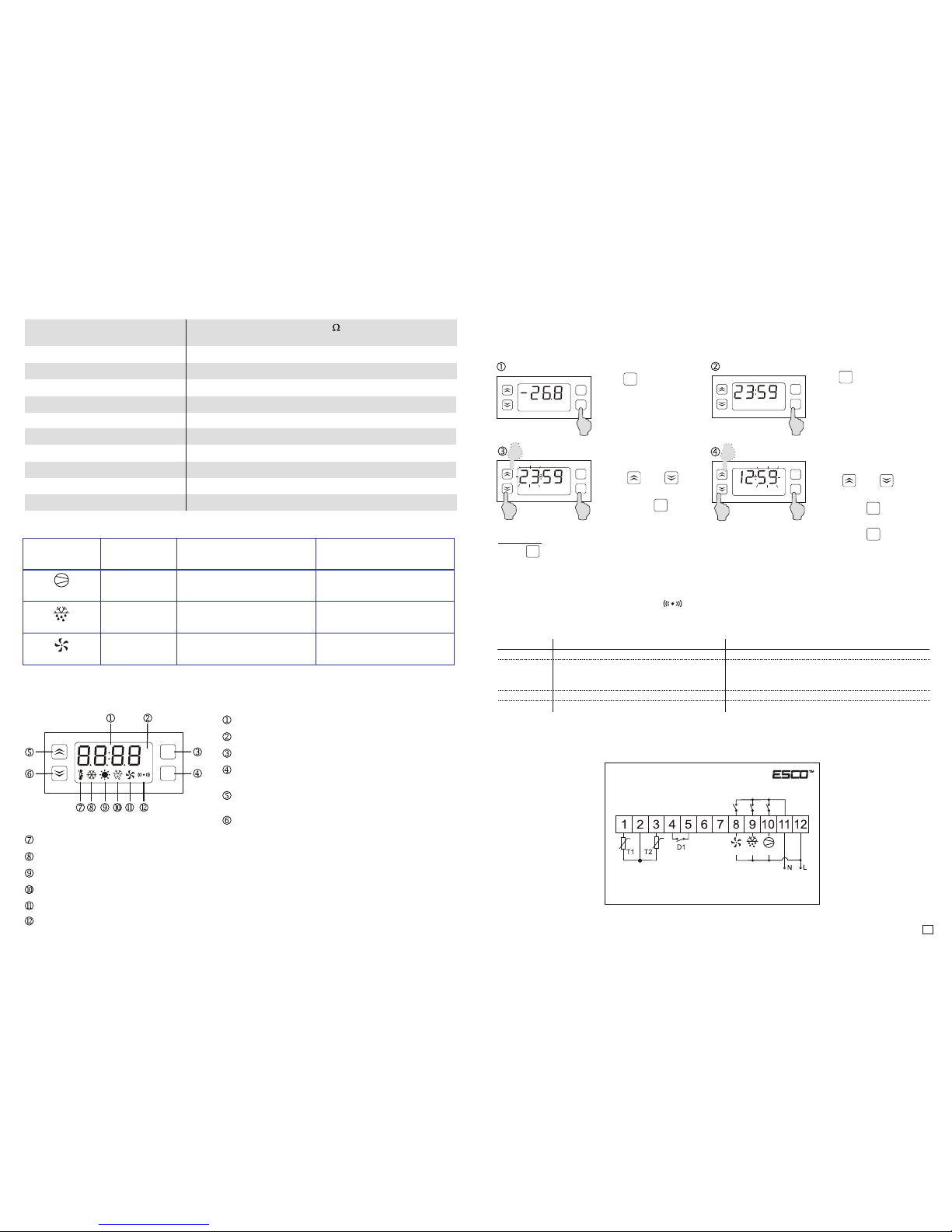
3. FRONT PANEL.
°C
°F
M
set
Temperature setting signalling
Compressor operation signalling. LIGHTS: compressor operates; BLINKS: waits for start-up (see F21)
Heating output signalling. LIGHTS: output active; BLINKS: waits for start-up (see F21)
Defrosting signalling. LIGHTS: automatic defrosting mode ; BLINKS: manual defrosting
Fans operation signalling. LIGHTS: fans operate
Emergency states signalling. BLINKS: alarm active
Temperature/time display
Temperature unit indicator
Entry to the parameters menu
Temperature setting button
by pressing you can displat current time
Value increasing button
pressinf fro more than 5 sec. Forces heating/cooling
Value decreasing button
holding it you can display evaporator temperature
pressing for more than 5 sec. forces defrosting cycle
5.5. REAL TIME CLOCK (RTC).
Controller has a built-in real time clock due to defrosting function can be carried out at specified
hours during the day (maximally 6 cycles per day). The clock can be set in F60 parameter or in
normal operation mode.
Press button
Display indicates
Current time.
Using:
or
button set the hour and
Confirm with
set
set
set
set
°C
M
set
Zatwierdź nastawę
przyciskiem
set
Press button for 3 sec
to enter the time setting
mode.
Hours block starts to
flash.
Using:
or
Set the minute and
confirm with
Minutes block starts to
Flash.
M
M
set
set
M
set
M
Remarks:
Press button in any time to cancel the setting.
Clock setting in case of controller power failure can be maintained for minimum 3 days.
6. ALARM MESSAGES.
6
When alarm activates the indicator starts blinking and the sound signaller (beep) will be
activated (when F83=1). According to the occurence controller turns on/off output and the front
panel displays one of the following alarm messages:
Statement Occurence
A11 bistate input activation.
A21 chamber sensor error:
OPE - open circuit
SHr - short circuit
A22 Evaporator sensor error
A99 Timer setting ime elapsed
Outputs signalling
All outputs inactive
Compressor output operates in accordance
with F22 and F23 parameters, other outputs
inactive
All outputs inactive
All outputs inactive
ES-30
7. WIRING DIAGRAM.
T1 - chamber sensor
T2 - evaporator sensor
D1 - bistate input
Power supply
230V~
8(2)A
8A 250V~
5
10 cycles
Input: Relay:
Maximum resistive charge
(e.g. Heater):
Maximum inductive
charge (e.g. Engine):
Compressor
Defrosting
Fan
8A 250V~
5
10 cycles
8A 250V~
5
10 cycles
8A, 1500W
8A, 1500W
8A, 1500W
2A, 400W, 0.5HP(0.5KM)
2A, 400W, 0.5HP(0.5KM)
2A, 400W, 0.5HP(0.5KM)
Fan
Defrost.
Compressor
Page 3
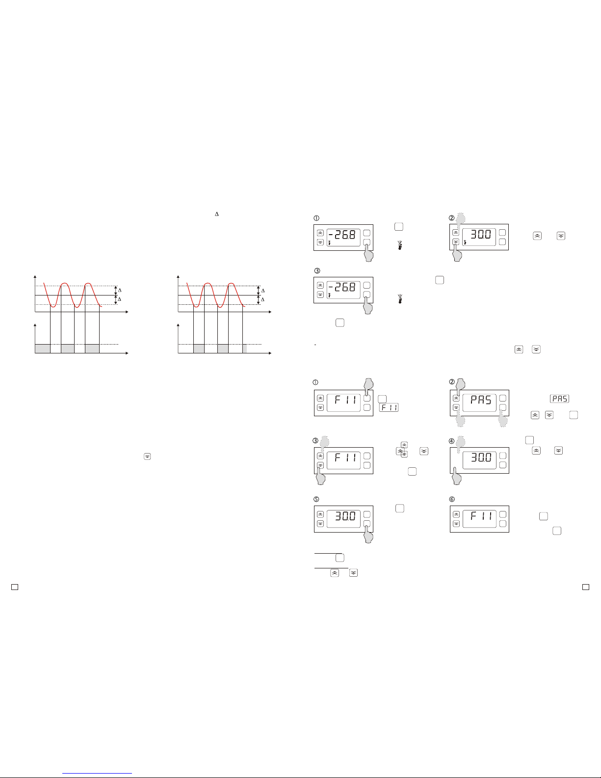
Enter the menu pressing
button for 5 sec., Until
command
displays.
4. CONTROLLER HANDLING.
4.1. TEMPERATURE SETTING.
Press button
for 2 seconds
Confirm the set with
Button.
Diode lights up.
Using:
or
set the desired
temperature.
Diode goes off.
4.2. PROGRAMMING OF PARAMETERS.
Using key confirm
the new parameter
value and return to the
parameter list.
Using or button
choose the parameter
you want to change and
enter with key.
Information:
To improve quick increasing or decreasing the settings values hold the or button
constantly for at least 1 sec.
set
set
set
set
set
set
set
°C
°C
°C
°C
M
set
M
set
M
set
M
set
°C
M
M
M
M
set
Remarks:
– press button in any time to cancel the setting
– the setting change can be limited by F13 and F14 parameters
M
set
M
M
set
set
If the access to the menu
is protected,
command displays.
Using , and
buttons enter the
password and confirm
with
M
set
Using or button
set the desired
parameter value.
Finish programming
pressing button or
enter the “End” command
and press the key
or wait 30 sec. without
pressing any button.
Information:
Hold or button for at least 1 sec. to improve quick increasing and decreasing of setting
values.
Controller is used to maintain T temperature with desired hysteresis T in cooling or heating
devices. Actuator control is carried out by the relay output and the temperature measurement is
made by the chamber temperature sensor. The second temperautre sensor is applied in cooling
applications and used to readt the temperature of the evaporator. It allows you to control the defrost
and the evaporator fan operation according to the indications. It improves the efficiency of the
control system significantly. The principle of operation of the temperature control when cooling and
heating:
5. GENERAL DESCRIPTION.
5.2 DEFROSTING.
5.3. EVAPORATOR FAN.
5.1. ADJUSTMENT.
Depending on the application, select the type of periodical defrosting of the evaporator:
- natural (F36=0; F37=0; F38=ON)
- due to electric heaters (F36=0 or 1; F37=0; F38=ON or OFF )
- due to hot gas (F36=0 or 1; F37=1; F38=ON or OFF)
Defrosting control is carried out automatically and turned on:
- periodically from time to time (F35=1)
- depending on the total operation time of the compressor (F35=2). (The lower capacity of the
cooling system, the less oftem defrosting cycles follow)
- at certain times during the day ( max 6 cycles per day).
The end of the defrosting cycle follows after lapse of time F33 or after exceeding evaporator sensor
temperature above F32 value - it is specified by F36 parameter.
In difficult operation conditions, when there is a need for additional defrosting of the evaporator, the
process can be started manually by pressing button for 5 seconds. Defrosting diode flashes
when defrosting manually.
Depending on the needs, evaporator fan can operate in one of the seven operation modes
described in the “fan” section in point 4.3. The fan operation is dependent from compressor
operation or the evaporator temperature sensor. Due to advanced settings you can choose the
optimal fan operation mode and get a high cooling efficiency. During defrosting, fans are operating
or are turned off. Parameter F38 specifies this mode. When natural defrosting, it is recommended
to turn on the fan to raise the efficiency of the operation.
5.4. BISTATE INPUT.
The controller has a bistate input D1 to indicate emergency states, e.g system failure, pressure
control or safety thermostat activation, etc. The type of the input (normally close/opened) is
programmed by F50 parameter. After bistate input activation, the controller turns off the outputs,
turns on the beeper and the display indicates A11 code. Emergency states signalling can be
maintained, until the alarm reset by using the buttons (F50=2 or 4).
6°C
4°C
Output
Time
Time
Temp.
0
1
T=1°C
T=1°C
T=1°C
T=1°C
COOLING HEATING
89°C
T=90°C
Output
Time
Time
Temp.
0
1
91°C
T=5°C
5
3
M
Remarks:
- press button to cancel the parameter setting
Page 4
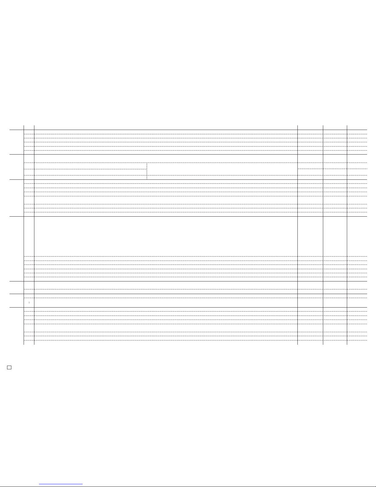
4.3. DESCRIPTION OF THE PARAMETERS.
Code:
Units:
Default:Description:
F11
°C/°F
0.0Temperature setting value. Range of changes is limited by the F14 and F13 parameters.
F12
°C/°F
1.0Hysteresis (temperature control accuracy).
Range:
F14...F13
0.1...20.0
Group:
Adjustment
F13
°C/°F
302.0Maximum temperature value possible to set by the user.
F14
°C/°F
-58.0Minimum temperature value possible to set by the user.
-58.0...302.0
-58.0...302.0
F18
°C/°F
0.0Evaporator sensor calibration. This is the value of rescaling the evaporator sensor in relation to actually measured temperature. -20.0...+20.0
F19
°C/°F
0.0Temperature sensor calibration. This is the value of rescaling the temperature sensor in relation to actually measured temperature. -20.0...+20.0
F21
Minutes
3.0
Minimum compressor stoppage time. It also means the delay time of switching the compressor after giving power supply.
Parameter protects the compressor against too frequent switching in case of power failure.
F22
%
0The factor of compressor operation time when chamber sensor failure.
0.0...10.0
0...100
Compressor
F23
Minutes
60Work/stoppage mode of the compressor after chamber sensor failure.
Operation and stoppage time of the compressor after chamber sensor failure is determined
on the basis of these two parameters.
Operation time: ton = F22xF23 ; Stoppage time: toff = F23-ton
Example: F22=20%; F23=60min then ton = 12min ; toff = 48min
F29
-
COOL
Main output operation mode. COOL = cooling ; HEAT = heating
5...999
COOL/HEAT
F31
Hours
12.0Interval between defrosting cycles. 0.1...99.9
F32
°C/°F
15.0Ending of the defrosting temperature.
F33
Minutes
30Maximum defrosting cycles duration.
0.0...100.0
1...99
F34
Minutes
5Dripping time of the evaporator after defrosting cycle. It is also the delay time of switching the compressor on after defrosting.
F35
-
OFF
Defrosting cycles control form. OFF - defrosting off, 1 - automatically, from time to time equals toF31,
2 - automatically, when the total operation time of the compressor reaches a value of F31, 3 - automatically, according to the real-time
0...99
OFF,1, 2, 3
F36
-
1End of defrosting: 0 - after lapse of time F33; 1 - if the evaporator reaches the temperature of F32 or after lapse of time F33
F37
-
0Type of defrosting. 0 - electrical, 1 - with hot gas (compressor turned on when defrosting)
0, 1
0, 1
-
F38 OFFFan operation when defrosting. OFF - off, ON - on. (Recommended F38=ON when natural defrosting). OFF/ON
Defrosting
F41
-
1
Fan operation. There are 7 fan operation modes available: OFF - fan turned off.
1 - fan runs parallel to the compressor, is switched on after running the compressor with F42 delay and turned off after its stoppage with F43 delay.
2 - fan runs parallel to the compressor, is switched on before the running of the compressor with F42 lead and turned off after its stoppage with F43 delay.
3 - fan operates according to the evaporator temperature sensor, is activated when the value drops below the temperature F44 and turned off when
the evaporator sensor temperature rises above the value: F44+F45
4 - fan operates according to the evaporator temperature sensor, is activated when the value rises above temperature F44 and turned off,
when the evaporator sensor temperature drops below the value: F44-F45
5 - fan runs with the compressor. During the stoppage of the compressor, fan operates periodically: turned on for F46 time, turned off for F47 time.
Attention! During defrosting, the fan operation is specified by F38 parameter.
OFF,1...6
F42
Seconds
30Lead/delay time of the fan run before/after the compressor run. Parameter is considered, when F41=1 and 2.
F43
Seconds
0Delay time of the fan stoppage after stopping the compressor. Parameter is considered, when F41=1 and 2.
0...999
0...999
F44
°C/°F
-10.0Fan switching temperature. Parameter is considered, when F41=3 and 4. -58.0...302.0
F45
°C/°F
5.0Evaporator sensor temperature hysteresis. Parameter is considered, when F41=3 and 4.
F46
Minutes
10Fan operation time during the stoppage of the compressor, when F41=5
0.1...50.0
0...999
F47
Minutes
10Fan stoppage time during the stoppage of the compressor, when F41=5 0...999
F50
-
0
Bistate input D1: 0 - unused; 1 - alarm when short-circuit; 2 - alarm when short-circuit with maintaince of alarm signalling;
3 - alarm when opened; 4 - alarm when opened with maintance of alarm signalling
F80
-
OFFPassword to access the configuration menu. OFF - password protection inactive. F80 = 0000 - no password
0...4
0000...9999
F81
-
°CTemperature unit °C/°F.
F98
-
-Reserved.
°C/°F
-
F99
-
-Controller test. Disconnect output device to make the test! Otherwise the system can crash. -
Fan
End Exit.
F59 YESEvaporator sensor: YES - active, NO - inactive YES/NO
F61-Six following defrosting runs during the day.
OFF - no defrosting
00:00...23:59
OFF
F60
Hour:min
-
Real-time clock setting (RTC).
00:00...23:59
F66
F85
Hours
-Timer current time. -
F86
-
NOTimer zeroing.
F87
Hours
OFF
Timer time setting. After lapse of the time, controller turns off all outputs, turns on the beeper and the display indicates A99 code.
You can check the current time of the timer in F85 parameter or reset counting with F86 parameter. OFF - timer function inactive.
YES/NO
0000...9999
OFF
Inputs
RTCOthers
Hour:min
-
4
 Loading...