

Esco Class II User And Service Manual
User
and S
ervice
Thank you for purchasing this E
sco Biological Safety Cabinet.
For Technical Service, contact
Class II
Esco Airstream
Class (AC2
- E/S/D/G/N)
II
BSC
User and Service Manual
Please read this manual thoroughly to familiarize yourself with the
many unique features and exciting innovations we have built into
your new equipment. Esco provides many other resources at our
website, www.escoglobal.com, to complement this manual and
help you enjoy many years of productive and safe use of your Esco
products.
North America
Esco Technologies, Inc.
2940 Turnpike Drive, Units 15-16 •Hatboro, PA 19040, USA
Toll-Free USA and Canada 1-877-479-3726
Tel 215-441-9661 • Fax 215-441-9660
us.escoglobal.com • usa@escoglobal.com
Rest of the World
Esco Micro Pte. Ltd.
21 Changi South Street 1 • Singapore 486777
Tel +65 6542 0833 • Fax +65 6542 6920
www.escoglobal.com • mail@escoglobal.com
Version F - Released July 2013
Manual
Biological Safety Cabinet

Copyright Information
Sentinel
® and Airstream
® are registered trademarks of Esco.
© Copyright 2013 Esco Micro Pte Ltd. All rights reserved.
The information contained in this manual and the accompanying product is copyrighted and all rights are
reserved by Esco.
Esco reserves the right to make periodic minor design changes without obligation to notify any
person or entity of such change.
“Material in this manual is provided for informational purposes only. The contents and the product described in
this manual (including any appendix, addendum, attachment or inclusion), are subject to change without
notice. Esco makes no representations or warranties as to the accuracy of the information contained in this
manual. In no event shall Esco be held liable for any damages, direct or consequential, arising out of or related
to the use of this manual.”

i
INTRODUCT
ION
i
Table of Contents
iii Warranty Terms and Conditions
v 2. Safety
Warning
v 3. Limitation of Liability
vii
Declaration of Conformity
2 2.1 Sentinel Control System
5
2.2.3 Field Calibration
11 3.1 Sash Window Operation
11
3.1.1 Sash Window
State
12
3.1.3 Using Sash Window
12
3.2.2 Turning off the BSC
12 3.3 Working in the BSC
14 3.5 UV Lamps
(If Present)
14 3.6 Decontamination and Disinfecting Agents
15 3.7 Gaseous Decontamination
20 5.1 Installation Check
21 5.2 Cabinet Field Certification
22 5.3.2 Adjusting Airflow
23 5.4 Parts Replacement
27
5.4.3 Fluorescent Lamp(s) Replacement Procedure
27
5.4.4 UV Lamp Replacement Procedure
Table of Contents
v Introduction
v 1. Products Covered
vi 4. European Union Directives on WEEE and RoHS
1 Chapter 1 - Product Information
1 1.1 Quick View
2 Chapter 2 - Sentinel Control System
3 2.2 Menu Options
4 2.2.1 Settings
5 2.2.2 Setting Mode
6 2.2.4 Admin Settings
8 2.3 Stopwatch and Experiment Timer (Only for non-motorized sash BSC)
8 2.4 Alarms and Warnings
9 2.5 Diagnostic Mode
10 2.5 Standby Mode (Half Speed)
11 Chapter 3 - Basic Cabinet Operation
11 3.1.2 Operating Motorized Sash Window (Only for BSC with motorized sash
window)
12 3.2 Starting and Shutting Down the BSC
12 3.2.1 Turning on the BSC
13 3.4 Working Ergonomics
15 3.8 Further Information
17 Chapter 4 - Maintenance
17 4.1 Scheduled Maintenance
19 4.2 Maintenance/Service Log
20 Chapter 5 - Maintenance and Re-certification of the Cabinet
21 5.3 Performing Calibration / Certification
21 5.3.1 Setting Cabinet in Maintenance Mode
23 5.4.1 Filter Replacement Procedure
26 5.4.2 Blower Replacement Procedure
28 5.4.5 Airflow Sensor Replacement Procedure
Class II Biological Safety Cabinet
ii
30 6.1 Decontamination Agents
30
6.1.1 Formalin/Paraformaldehyde Decontamination
322
6.2 Recommended Decontamination Sealing Method
533
8.1 AC2
-
_E_ Engineering Drawing
55
8.3 AC2
-
_E_ and AC2
-
_S_ General Specifications
57
8.5
AC2-_G_ Engineering Drawing
59
8.7
AC2-2N7 Engineering Drawing
30 Chapter 6 - Decontamination
30 6.1.2 Chlorine Dioxide Decontamination
30 6.1.3 Hydrogen Peroxide Decontamination
344 Chapter 7 - Troubleshooting
344 7.1 Electrical and Mechanical Troubleshooting
51 7.2 Software Troubleshooting
533 Chapter 8 - Engineering Details
54 8.2 AC2-_S_ Engineering Drawing
56 8.4 AC2-_D_ Engineering Drawing
58 8.6 AC2-_D_ and AC2-_G_ General Specifications
61 8.8 AC2-2N7 General Specifications

iii
Warranty Terms and Conditions
Esco products come with a limited warranty. The warranty period will vary depending on the
product purchased, beginning on the date of shipment from any Esco international warehousing
location. To determine which warranty applies to your product, refer to the appendix below.
Esco's limited warranty covers defects in materials and workmanship. Esco's liability under this
limited warranty shall be, at our option, to repair or replace any defective parts of the equipment,
provided that these parts, if proven to the satisfaction of Esco, were defective at the time of being
sold and that all defective parts shall be returned, properly identified with a Return Authorization.
This limited warranty covers parts only, and not transportation/insurance charges.
This limited warranty does not cover:
• Freight or installation (inside delivery handling) damage. If your product was damaged in
transit, you must file a claim directly with the freight carrier.
• Products with missing or defaced serial numbers.
• Products for which Esco has not received payment.
• Problems that result from:
- External causes such as accident, abuse, misuse, problems with electrical power,
improper operating environmental conditions.
- Servicing not authorized by Esco.
- Usage that is not in accordance with product instructions.
- Failure to follow the product instructions.
- Failure to perform preventive maintenance.
- Using accessories, parts, or components not supplied by Esco.
- Damage by fire, floods, or acts of God.
- Customer modifications to the product.
• Consumables such as filters (HEPA, ULPA, carbon, pre-filters) and fluorescent / UV bulbs.
Factory installed, customer specified equipment or accessories are warranted only to the extent
guaranteed by the original manufacturer. The customer agrees that in relation to these products
purchased through Esco, our limited warranty shall not apply and the original manufacturer's
warranty shall be the sole warranty in respect of these products. The customer shall utilize that
warranty for the support of such products and in any event not look to Esco for such warranty
support.
Esco encourages all users to register their equipment online at
www.escoglobal.com/warranty_registrations.php or complete the warranty registration form
included with each product.
ALL EXPRESS AND IMPLIED WARRANTIES FOR THE PRODUCT, INCLUDING BUT NOT LIMITED TO ANY
IMPLIED WARRANTIES AND CONDITIONS OF MERCHANTABILITY AND FITNESS FOR A PARTICULAR
PURPOSE ARE LIMITED IN TIME TO THE TERM OF THIS LIMITED WARRANTY. NO WARRANTIES,
WHETHER EXPRESS OR IMPLIED, WILL APPLY AFTER THE LIMITED WARRANTY PERIOD HAS EXPIRED.
ESCO DOES NOT ACCEPT LIABILITY BEYOND THE REMEDIES PROVIDED FOR IN THIS LIMITED
WARRANTY OR FOR SPECIAL, INDIRECT, CONSEQUENTIAL OR INCIDENTAL DAMAGES, INCLUDING,
WITHOUT LIMITATION, ANY LIABILITY FOR THIRD-PARTY CLAIMS AGAINST YOU FOR DAMAGES, FOR
PRODUCTS NOT BEING AVAILABLE FOR USE, OR FOR LOST WORK. ESCO'S LIABILITY WILL BE NO
Class II Biological Safety Cabinet
iv
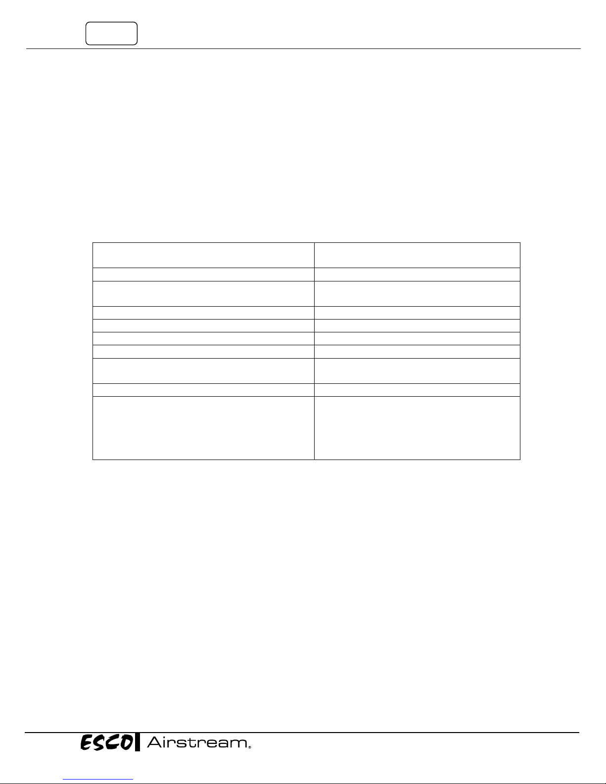
Biological Safety Cabinets, Laminar Flow Cabinets,
Laboratory Fume Hoods
2 years limited
4 years limited for Ascent Opti
Cleanroom Equi
pment
1 year limited
Laboratory Ovens and Incubators
1 year limited
CO2
Incubators
2 years limited
Containment/Pharma Products
2 years limited
5 years limited
Benchtop Incubator
2 years limited
3 years limited for MiniPro, MaxPro, Provocell
MORE THAN THE AMOUNT YOU PAID FOR THE PRODUCT THAT IS THE SUBJECT OF A CLAIM. THIS IS
THE MAXIMUM AMOUNT FOR WHICH ESCO IS RESPONSIBLE.
These Terms and Conditions shall be governed by and construed in accordance with the laws of
Singapore and shall be subject to the exclusive jurisdiction of the courts of Singapore.
Technical Support, Warranty Service Contacts
USA: 1-888-479-ESCO
Singapore: +65 6542 0833
Global Email Helpdesk: support@escoglobal.com
Visit http://escoglobal.com to talk to a Live Support Representative
Distributors are encouraged to visit the Distributor Intranet for self-help materials.
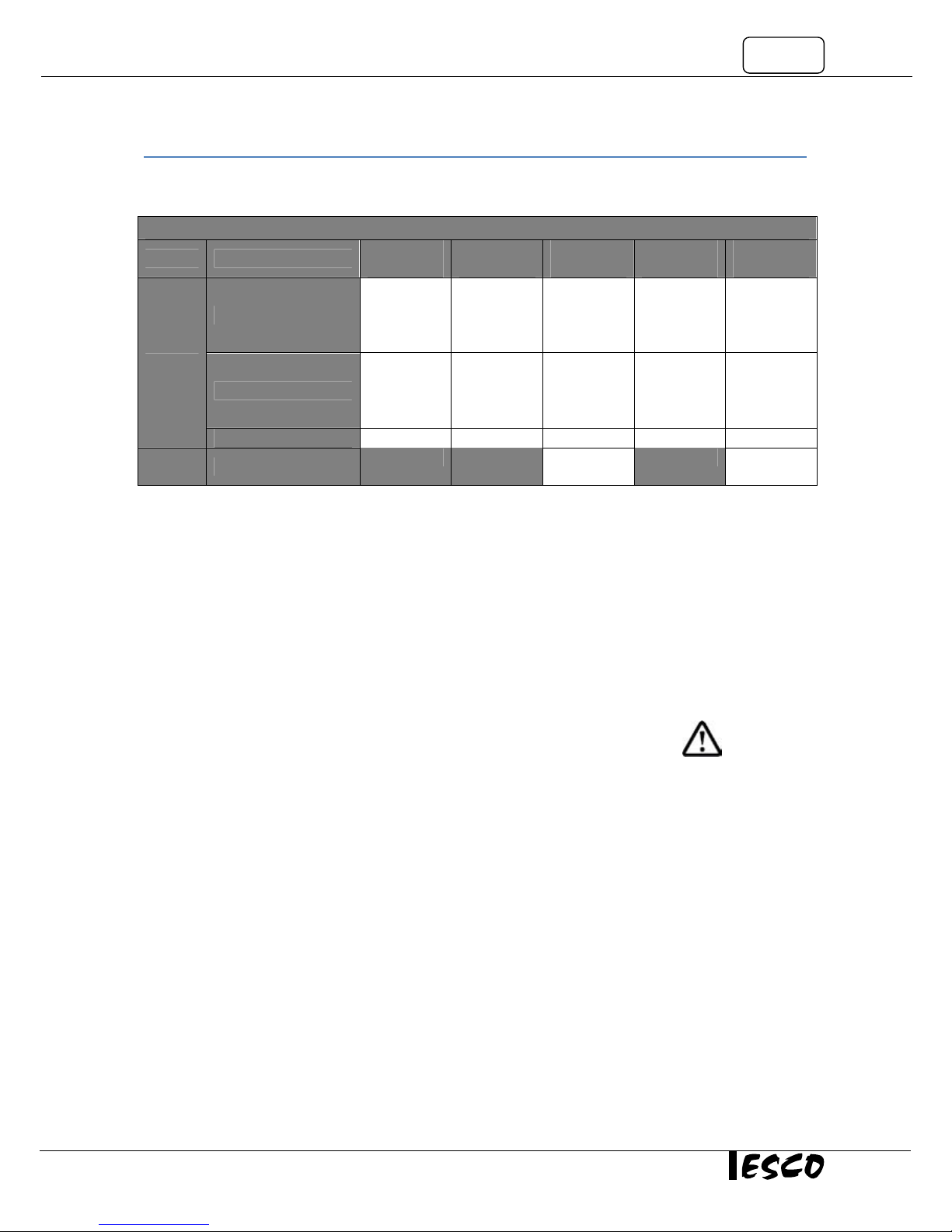
Product Appendix, Warranty Listings
HEPA-Filtered Cabinets (except Streamline brand)
Ductless Fume Hoods
Ultra-low Temperature Freezer
4 years limited
6 years for Ascent Max
5 years on compressor
2 years limited for Spectrum
Thermal Cyclers
2 years on blocks and Peltier units
2 years on all electronic components
3 years on the housing and fans
Policy updated on 1st January 2012
Applies to all units ordered on and after 1st January 2012
v
AC2-3S8-M
AC2-4S8-M
AC2-5S8-M
AC2-6S8-M
Introduction
1. Products Covered
Model Electrical Rating
220-240 VAC, 50/60Hz, 1Φ
Esco Class II Biological Safety Cabinet
0.6 meters
2 feet
AC2-2E8
AC2-2S8
0.9 meters
3 feet
AC2-3E8
AC2-3E8-M
AC2-3S8
1.2 meters
4 feet
AC2-4E8
AC2-4E8-M
AC2-4S8
1.5 meters
5 feet
AC2-5E8
AC2-5E8-M
AC2-5S8
1.8 meters
6 feet
AC2-6E8
AC2-6E8-M
AC2-6S8
Airstream
Airstream
Duo
110-130 VAC, 50/60Hz, 1Φ
90-110 VAC, 50/60Hz, 1Φ AC2-2N7 AC2-3N7 AC2-4N7 AC2-5N7 AC2-6N7
220-240 VAC, 50/60Hz, 1Φ
AC2-2E9
AC2-2S9
AC2-4D8
AC2-3E9
AC2-3E9-M
AC2-3S9
AC2-3S9-M
AC2-4E9
AC2-4E9-M
AC2-4S9
AC2-4S9-M
AC2-4G8
AC2-5E9
AC2-5E9-M
AC2-5S9
AC2-5S9-M
AC2-6D8
2. Safety Warning
• Anyone working with, on or around this equipment should read this manual. Failure to read,
understand and comply with the instructions given in this manual may result in damage to the unit,
injury to operating personnel, and / or poor equipment performance.
• Any internal adjustment, modification or maintenance to this equipment must be undertaken by
qualified service personnel.
• The use of any hazardous materials in this equipment must be monitored by an industrial hygienist,
safety officer or some other suitably qualified individuals.
• Before you process, you should thoroughly understand the installation procedures and take note of
the environmental / electrical requirements.
• In this manual, important safety related points will be marked with the symbol.
• If the equipment is used in a manner not specified by this manual, the protection provided by this
equipment may be impaired.
AC2-6E9
AC2-6E9-M
AC2-6S9
AC2-6S9-M
AC2-6G8
3. Limitation of Liability
The disposal and / or emission of substances used in connection with this equipment may be governed by
various local regulations. Familiarization and compliance with any such regulations are the sole responsibility
of the users. Esco’s liability is limited with respect to user compliance with such regulations.
Class II Biological Safety Cabinet
vi
4. European Union Directive on WEEE and RoHS
The European Union has issued two directives:
• Directive 2002/96/EC on Waste Electrical and Electronic Equipment (WEEE)
This product is required to comply with the European Union’s Waste Electrical & Electronic
Equipment (WEEE) Directive 2002/96/EC. It is marked with the following symbol:
Esco sells products through distributors throughout Europe. Contact your local Esco distributor
for recycling/disposal.
• Directive 2002/95/EC on Restriction on the use of Hazardous Substances (RoHS)
With respect to the directive on RoHS, please note that this cabinet falls under category 8 (medical
devices) and category 9 (monitoring and control instruments) and is therefore exempted from
requirement to comply with the provisions of this directive.
vii
Declaration of Conformation
In accordance to EN ISO/IEC 17050-1:2010
We, Esco Micro Pte Ltd
of 21 Changi South Street 1
Singapore, 486777
Tel: +65 6542 0833
Fax: +65 6542 6920
declare on our sole responsibility that the product:
Category : Class II Biological Safety Cabinet
Brand : Airstream
Model : AC2-2E8, AC2-3E8, AC2-4E8, AC2-5E8, AC2-6E8, AC2-3E8-M, AC2-4E8-M,
AC2-5E8-M, AC2-6E8-M, AC2-2S8, AC2-3S8, AC2-4S8, AC2-5S8, AC2-6S8,
AC2-3S8-M, AC2-4S8-M, AC2-5S8-M, AC2-6S8-M
in accordance with the following directives:
2006/95/EEC : The Low Voltage Directive and its amending directives
2004/108/CE : The Electromagnetic Compatibility Directive and its amending directives
has been designed to comply with the requirement of the following Harmonized Standard:
Low Voltage : EN 61010-1:2001
EMC : EN 61326-1:2006 Class B
Design/ Performance Criteria : EN 12469 (2000) Class II Biological Safety Cabinet
More information may be obtained from Esco’s authorized distributors located within the European Union. A
list of these parties and their contact information is available on request from Esco
_______________________________
XQ Lin
Group CEO, ESCO
This Declaration of Conformity is only applicable for 230VAC 50/60Hz units
.
Class II Biological Safety Cabinet
viii
Declaration of Conformation
In accordance to EN ISO/IEC 17050-1:2010
We, Esco Micro Pte Ltd
of 21 Changi South Street 1
Singapore, 486777
Tel: +65 6542 0833
Fax: +65 6542 6920
declare on our sole responsibility that the product:
Category : Class II Biological Safety Cabinet
Brand : Airstream Duo
Model : AC2-4D8, AC2-6D8, AC2-4G8, AC2-6G8
in accordance with the following directives:
2006/95/EEC : The Low Voltage Directive and its amending directives
2004/108/CE : The Electromagnetic Compatibility Directive and its amending directives
has been designed to comply with the requirement of the following Harmonized Standard:
Low Voltage : EN 61010-1:2001
EMC : EN 61326-1:2006 Class B
Design/ Performance Criteria : EN 12469 (2000) Class II Biological Safety Cabinet
More information may be obtained from Esco’s authorized distributors located within the European Union. A
list of these parties and their contact information is available on request from Esco
_______________________________
XQ Lin
Group CEO, ESCO
This Declaration of Conformity is only applicable for 230VAC 50/60Hz units
.
1
Chapter 1 - Product Information
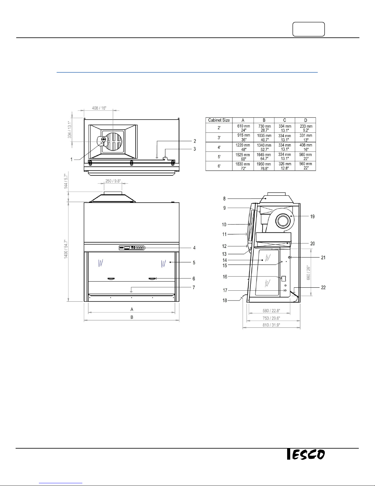
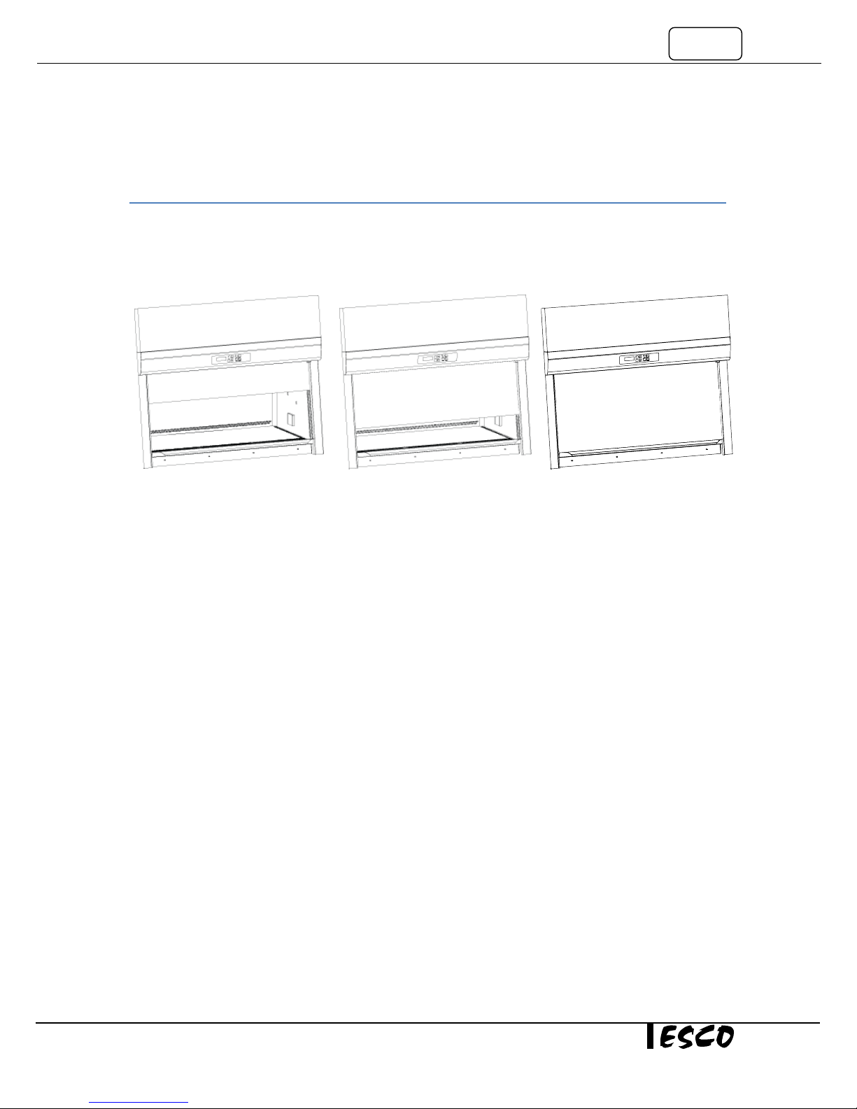
1.1. Quick View AC2 3G
1. Airflow Sensor
2. RS232 Port
3. Power Inlet
4. Sentinel Gold Control System
5. Sash Window
6. Sash Handle
7. Work tray
Figure 1.1. AC2 Gen 3 general parts.
8. Exhaust Collar (Optional)
9. Exhaust ULPA Filter
10. Electrical Panel
11. Curved Front Panel
12. Display Panel
13. Fluorescent Lamps
14. Side Window
Class II Biological Safety Cabinet
15. IV Bar Retrofit Kit Provision
16. Electrical Outlet Kit Provision
17. Service Fixture Kit Provision
18. Stainless Steel Armrest
19. ECM Blower
20. Downflow ULPA Filter
21. UV Lamp
22. Paper Catch (optional pre-filter)
2
Display
Chapter 2 - Sentinel Control System
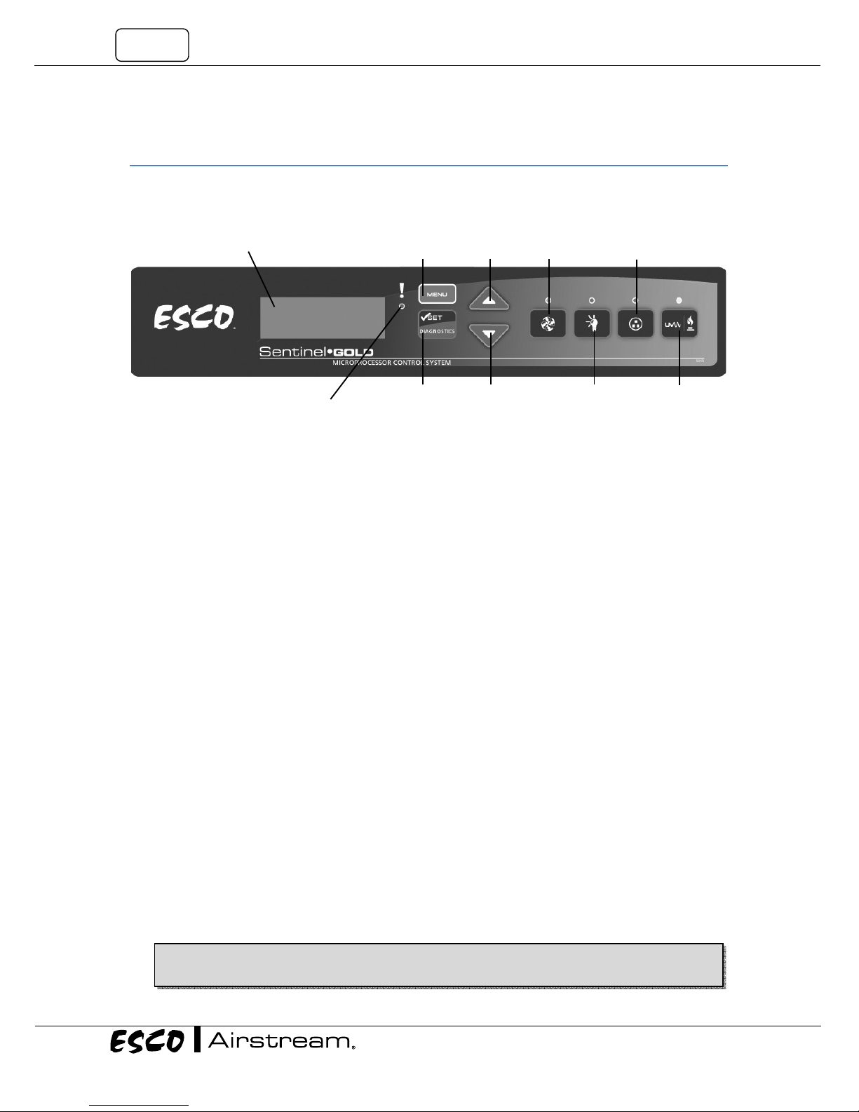
2.1. Sentinel Control System
LCD
1. Fan Button
o Turns on and turns off the fan.
o Activate Standby mode
2. Lamp Button
o Turns on and turns off the fluorescent lamps.
3. Socket Button
o Turns on and turns off the electrical socket (retrofit kit).
o The maximum rating of all the outlets in the cabinet is 5 A. If there is overload, the fuse will
blow.
4. UV/Gas Button
o Turns on and turns off the UV lamp.
o UV lamp can only be activated when the sash window is fully closed. Since the sash is
capable of filtering UV rays, users are protected from the harmful UV radiation.
5. Up (▲) and Down (▼) Arrow Button
o Moves the menu options upwards and downwards.
o Increases and decreases corresponding value inside one of the menu options.
o Moves the sash window upward and downward (for motorized sash BSC).
o For accessing the stopwatch and experiment timer function (for non-motorized sash BSC).
6. Set or Mute or Diagnostic Button
o To proceed to the next step, level or sequence inside the menu options.
o Mutes the fully opened sash and airfail alarm sound (during normal and quickstart mode).
o Enters diagnostic mode.
7. Menu Button
When you are entering menu options, the alarm will sound to indicate that the microprocessor is
not monitoring the operation of the cabinet. No further warnings will be given.
o To enter and exit from the menu options.
Visual
Alarm
Menu
Button
Set/Mute/
Diagnostic Button
Figure 2.1. Sentinel Gold general parts.
Up
Button
Down
Button
Fan
Button
Lamp
Button
Socket
Button
UV/Gas
Button
3
≤
≤
≤
≤
≤
≤
≤
≤
≤
≤
≤
≤
≤
≤
≤
≤
≤
≤
o To go back to the previous level of the menu options.
o To access maintenance mode from error condition.
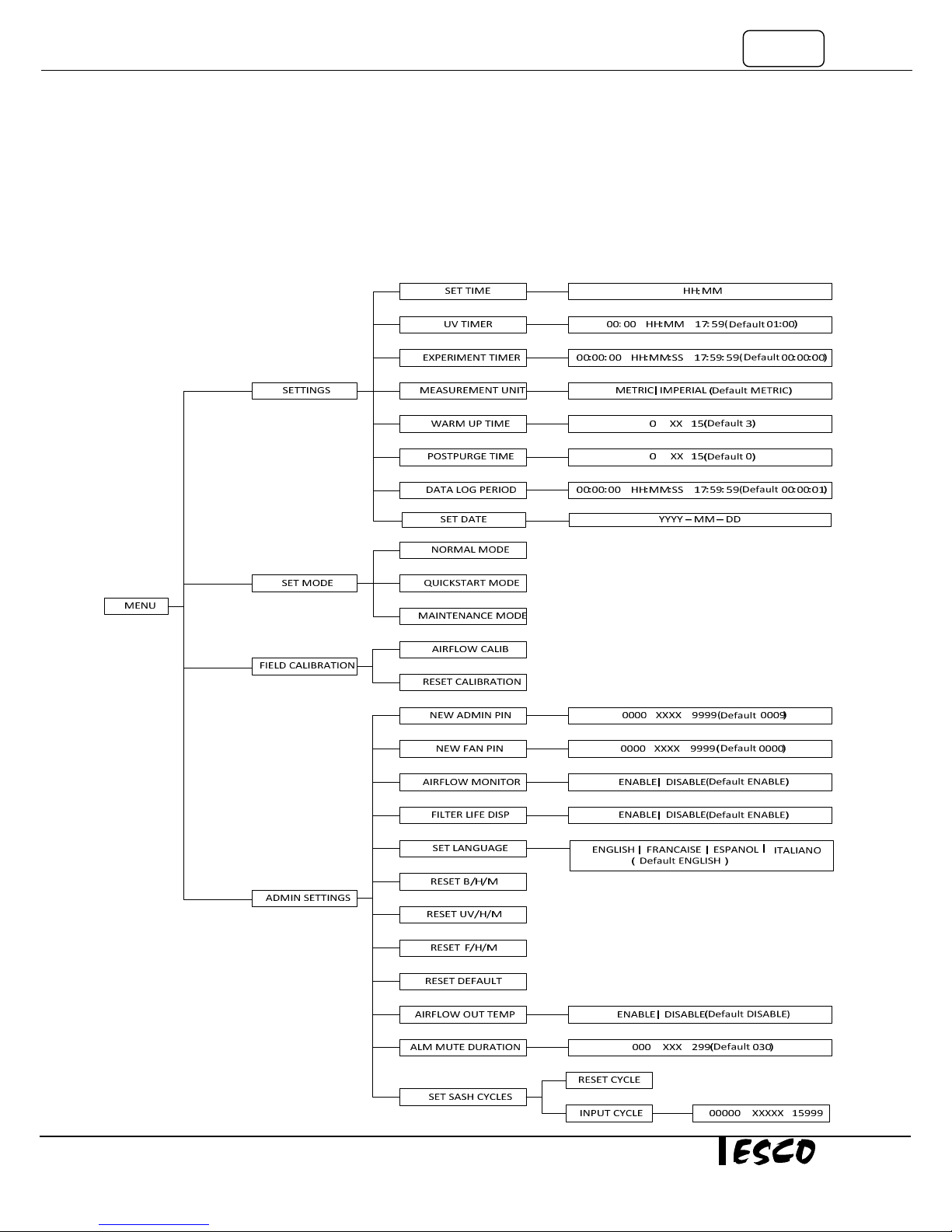
2.2. Menu Options
Please refer to the following diagram for complete reference to all menu options available.
Class II Biological Safety Cabinets
4
2.2.1. Settings
Users may use the settings menu function to customize the operation of the BSC to meet specific application
requirements. The settings menu can be entered using either FAN PIN or ADMIN PIN.
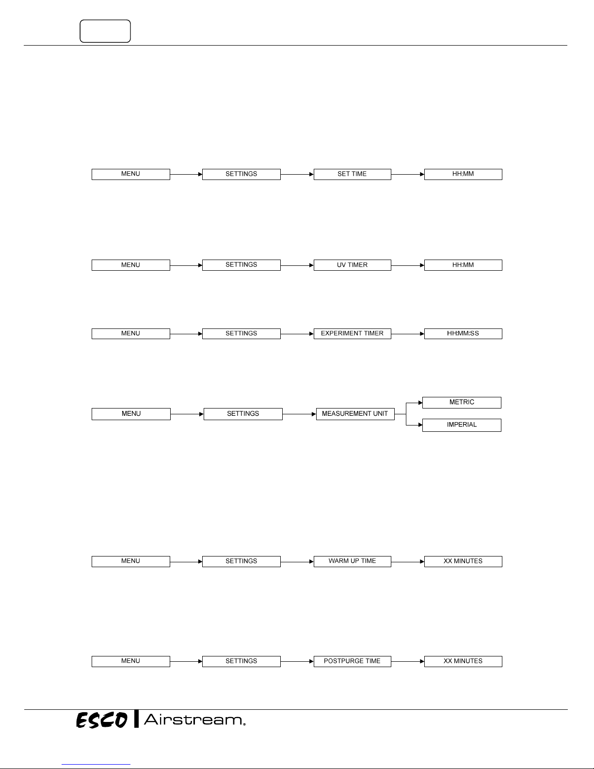
2.2.1.1. Set Clock (Time)
Users can set the time by increasing/decreasing the hour and minute values. The correct time will be
maintained even after the unit is turned off.
2.2.1.2. UV Timer (If UV present)
UV timer can be used to switch off the UV lamp automatically after a fixed period. The UV timer can be set up
to 18 hours. By default, the timer is set to 60 minutes. Esco does not recommend leaving the UV lamp on for
more than 60 minutes per decontamination cycle as it shortens the lifespan of the UV lamp. Unless the UV
timer is activated, the lamp has to be switched off manually.
2.2.1.3. Experiment Timer (Not applicable to motorized sash BSC)
Experiment timer is a countdown timer that can be used for critical experiment. Experiment timer can be set
between “00:00:00” and “17:59:59”.
2.2.1.4. Measurement Unit
Using this option, the user can select the unit in which air velocity is measured and displayed. The user can
choose between metric (m/s) and imperial (fpm) units.
2.2.1.5. Warm Up Time
There will be a warm up period before the BSC is fully functioning upon activation of the unit. This is to ensure
that the sensors, the blower, and the control system are stabilized, as well as to ensure the work zone is
purged of contaminants. The default setting is 3 minutes and the user can set it between 3 to 15 minutes.
(Note: Please note that WHO Laboratory Biosafety Manual (3rd edition) advocates 5 minutes purging time prior to start of
work while US Biosafety in Microbiological and Biomedical Laboratories (5th edition) advocates 4 minutes).
During the warm up period, the user can use the FAN button to turn off the blower, LIGHT button to turn on
and off the fluorescent lamp and MENU button. However, to be able to access the menu, the user needs to
input ADMIN PIN and even then, some sections of the menu (WARM UP and all FIELD CALIBRATION) are still
not accessible for the user. Entering the menu during this time will put the warm up period on pause.
2.2.1.6. Post Purge Time
After the user switches off the BSC blower, there will be a post-purge period, to ensure that all contaminants
are purged from the work zone. The default setting is zero minute (disabled) and user can set from 0 up to 15
minutes. It is recommended that BSC is purged for a minimum of 3 minutes after the work is complete.
(Note: Please note that WHO Laboratory Biosafety Manual (3rd edition) advocates 5 minutes post purging time after work
is completed while US Biosafety in Microbiological and Biomedical Laboratories (5th edition) advocates 4 minutes).
5
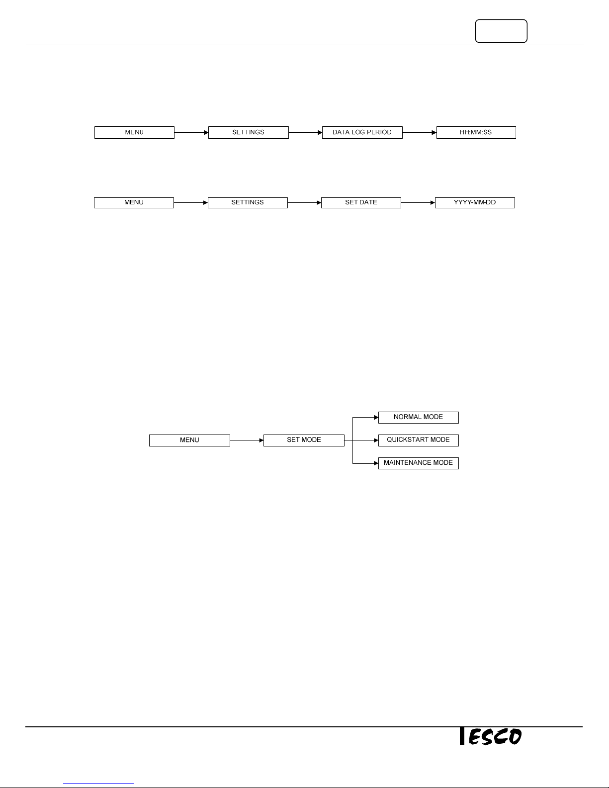
2.2.1.7. Data Log Period
Using RS232 communication port, the BSC can send data on the condition of the BSC to a PC. Data Log Period
option allows the user to control the amount of time within the BSC data sending procedure.
2.2.1.8. Set Date
Users can set the date by increasing/decreasing the year, month and day values. The correct date will be
maintained even after the unit is turned off.
To Set Date:
1. Press MENU button to enter the menu display – if the BSC is secured by a FAN PIN, then it will ask for
the PIN, otherwise go to step 3.
2. Use UP / DOWN button to enter the FAN PIN or ADMIN PIN digit by digit. Press SET button to confirm.
3. The alarm buzzer will sound.
4. Use UP / DOWN buttons to choose SETTINGS. Press SET button to confirm.
5. Use UP / DOWN buttons to choose SET DATE. Press SET button to confirm.
6. The time is set in YYYY–MM–DD format. Use UP / DOWN buttons to choose the year (YYYY). Press SET
button to confirm. Do the same for the month and day.
7. The display will show DATE SET for a few second and then return to SETTINGS.
8. Press MENU button twice to return to the main display.
2.2.2. Setting Mode
The BSC has three modes and two of which, normal mode and quickstart mode, can be used in daily activity.
Both of these modes can be seen and accessed when you enter the FAN PIN. The last mode, maintenance
mode is for the use of qualified personnel during maintenance.
2.1.2.1. Normal Mode
The Normal mode is activated by factory default except N series. In this mode, all alarms and interlocks are
enabled.
2.2.2.2. Quickstart Mode
Quickstart mode allows the user to activate the blower by simply lifting the sash from fully closed position and
the light by simply lifting the sash window to the operating position. In this mode, all alarms and interlocks are
enabled. This mode is activated by factory default in N series.
2.2.2.3. Maintenance Mode
Maintenance mode should only be accessed by qualified personnel during maintenance. In this mode, all
alarms are disabled and all interlocks are defeated.
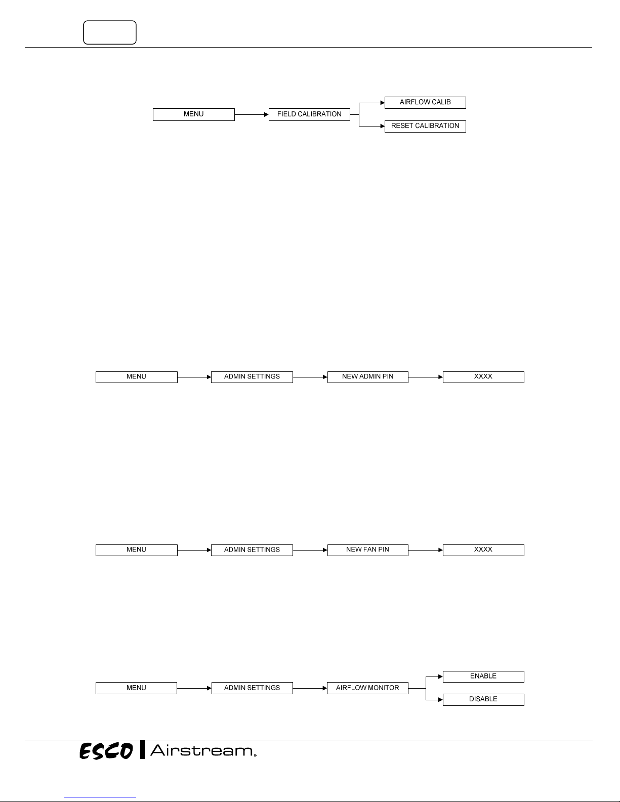
2.2.3. Field Calibration
The purpose of calibration is to ensure the accuracy of the airflow display and alarm (if present). This involves
measuring airflow with reference instrumentation and establishing reference between airflow sensor(s) on the
BSC to the standard reference. Calibration should only be carried out by qualified personnel. This section
presents a brief overview of the calibration menu function. For more information, refer to test report.
Class II Biological Safety Cabinets
6
2.2.3.1. Airflow Calibration
This option allows proper calibration and operation of the airflow sensor alarm. There will be two points to be
calibrated, namely inflow fail point and inflow nominal point.
2.2.3.2. Reset Calibration
This option allows the user to reset all values calibrated in the field and return it to the values obtained during
factory calibration.
2.2.4. Admin Settings
The admin menu allows you to change both FAN and ADMIN PIN. The reset blower, filter and UV hour meter
(if present) functions are usually used after the blower, filter or UV lamp is changed as they can easily serve as
an indication to the user on when the BSC needs maintenance. The reset default function will return the
options in the settings menu to their factory settings.
2.2.4.1. New ADMIN PIN (Default 0009)
ADMIN PIN restricts access to some of the more delicate menu functions, namely admin and field calibration,
which should only be accessed by qualified personnel. User must enter a four-digit ADMIN PIN before
accessing these menus.
ADMIN PIN can also be used to switch to maintenance mode from error condition.
2.1.4.2. New FAN PIN (Default 0000 - DISABLED)
FAN PIN restricts access to fan control and some parts of the menu, settings and set mode. User must enter
the four-digit PIN before switching the fan on or off. This feature prevents unauthorized personnel from
accessing critical control sections. It will also prevent unauthorized shutdown of the BSC when continuous
operation is required. FAN PIN is also needed to disable the alarm when the sash is fully raised and cleaning
needs to be performed.
It is recommended that the FAN PIN be issued only to personnel authorized to use the BSC. With FAN PIN, the
user can access admin and set mode parts of the menu.
Setting the PIN to 0000 will disable this feature. The FAN PIN is disabled by default. When the FAN PIN is
disabled, the BSC can be turned on and off without requiring PIN. However, to access the menu, the user is still
required to enter the FAN PIN (0000).
2.1.4.3. Airflow Monitor
Whenever the air velocity falls below the fail point, the air fail alarm will be triggered. This option is used to
enable/disable alarm. The alarm is enabled by default.
When the Airflow Monitor is disabled, the warm up period is removed but the airflow will not be displayed for
the first three minutes.
If the ambient temperature is outside of 18-30oC (which is the cabinet working temperature), the Airflow
Monitor is automatically disabled.
7
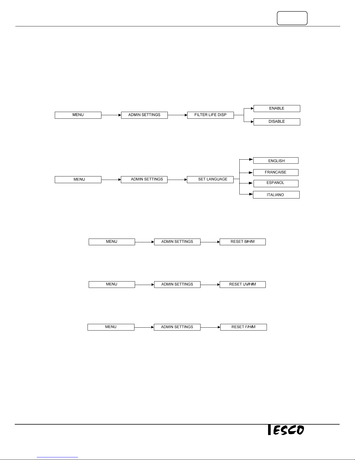
2.1.4.4. Filter Life Display
Using this option, the user can select whether the filter life is displayed or not.
Filter life is calculated based on the filter hour meter (F/H/M). The filter life display will count down according
to the amount of hours left in the filter hour meter with respect to filter life expectancy of 10,000 hours. When
the filter is changed, the F/H/M must be reset (please see section 2.1.4.8 to reset the F/H/M). Please note that
the life of the filter is dependent on multiple factors which include environmental air cleanliness. A dirty /
dusty environment will load the filter fast.
2.1.4.5. Set Language
Using this option, the user can select the language of messages displayed on the LCD.
2.1.4.6. Reset B/H/M
This option is used to reset the blower hour meter. The blower hour meter indicates how long the blower has
been in operation. There is no maximum value in blower hour meter. The counter value can be checked in the
diagnostic mode. The value can also provide some help in setting up maintenance schedule.
2.1.4.7. Reset UV/H/M (If UV is present)
This option is used to reset the UV lamp hour meter. The UV lamp hour meter indicates how long the UV lamp
has been in operation. Maximum counter is set at 2,000 hours (100%). The counter value can be checked while
in the diagnostic mode. Please reset the UV lamp hour meter after each UV lamp replacement.
2.1.4.8. Reset F/H/M
This option is used to reset the filter hour meter. The filter hour meter indicates how long the filter has been in
operation. Maximum counter is set at 10,000 hours (100%). The counter value can be checked while in the
diagnostic mode. Please reset the filter hour meter after each filter replacement.
2.1.4.9. Reset Default
User can reset default settings by choosing this option. The features being reset are warm up period (3
minutes), post-purge period (0 minute), UV timer (60 minutes) if present, measurement unit (metric), airflow
monitor (enabled), ADMIN PIN (0009), filter life display (disabled) and FAN PIN (0000).
Note that the calibration settings cannot be reset as it may cause the BSC to operate in an unsafe manner. The
hour meters cannot be reset using this function either.
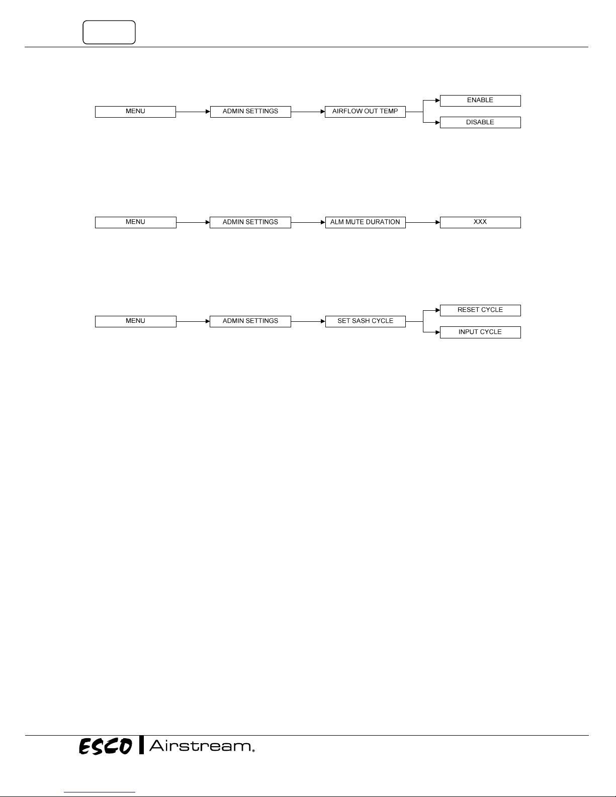
2.1.4.10. Airflow Out Temp
Using this option, the user can select whether or not to display the airflow when the ambient temperature is
out of the optimum temperature range, below 18oC (65oF) or above 30oC (86oF).
Class II Biological Safety Cabinets
8
2.1.4.11. Alarm Mute Duration
To mute unsafe sash height and airfail alarm for a certain period. The mute period can be set from 0 up to 299
seconds; the default value is 30 seconds. Alarm will be activated when sash is not in the working height and
when the inflow velocity is below the value prescribed by the standard the cabinet is designed or certified to.
2.1.4.12. Set Sash Cycle (Not applicable to non-motorized sash BSC)
To reset the sash cycles count to zero or to input the sash cycle count manually. The maximum value of sash
cycles is 16,000 and after which the motor needs to be replaced (e.g. as part of the preventive maintenance
program). The cycles will raise every sash move to up and down.
Warning message will be shown after the cycle value reaches 15,000.
• 1st warning: “Replace Sash Motor” – after sash reached 15,000 cycles.
• 2nd warning: “Stop Using Sash” - after sash reached 15,500 cycles.
• 3rd warning: “Sash Motor Locked” (sash motor cannot operate) - after sash reached 16,000 cycles.
2.1.4.13. Date Certified
This option is used to input the date the cabinet was certified. The year can be adjusted from 2000 to 2099.
2.3. Stopwatch and Experiment Timer (Only for non-motorized sash BSC)
• The stopwatch function can be started by pressing the UP button while the sash is in the safe/ready
position. Pressing UP button again while the stopwatch function is activated will stop and resume the
timer. Use the DOWN button to exit the stopwatch function and reset the timer. The timer in the
stopwatch function is counting up and is shown using the HH:MM:SS format.
• The experiment timer can be started by pressing the DOWN button while the sash is in the safe/ready
position. Pressing DOWN button while the experiment timer function is activated will stop and
resume the timer. Use the UP button to exit the experiment timer function and reset the timer. The
timer in the experiment timer function is counting down and is shown using the HH:MM:SS format.
Operator can use the SETTINGS | EXPERIMENT TIMER menu (refer to section 2.2.1.3) to set the
experiment timer.
2.4. Alarms and Warnings
A BSC uses alarms to indicate that the condition inside the BSC is not safe for the operator, so check the LCD
display to understand the cause of these alarms. The most common alarm is the SASH ALARM, which indicates
that the sash is neither at the normal operating height nor at fully closed position (UV mode) – this condition
can easily be corrected by putting the sash at the appropriate operation position.
Other alarms that indicate a failure or an error in the BSC system:
• AIRFLOW: NO! will be displayed if there is an airflow failure.
• SASH: ERROR POSITION indicates a failure in the sash detection system.
• SENSOR UNCALIBRATED will be displayed if the airflow velocity sensor is not yet calibrated.
9
Note: If the message "Call Service for re-certification" is displayed, it means the BSC certification has expired.
Call service or Esco's local distributor for re-certification.
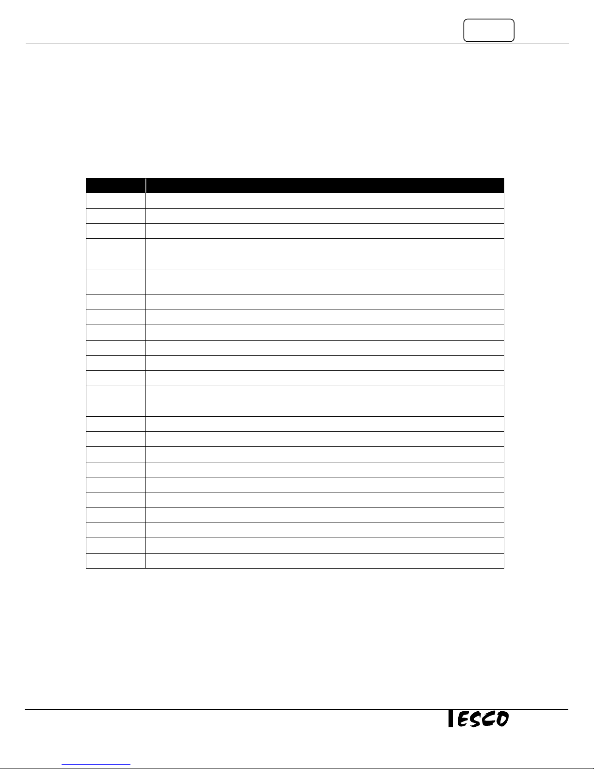
2.5. Diagnostic Mode
Diagnostic mode can be accessed by pressing the SET button. The diagnostic mode allows the user to know the
condition of the BSC or help the service engineer during maintenance and troubleshooting.
On Screen Explanation
MODE
VERSION
TEMPERATURE
B/H/M
SASH CYCLE
FILTER LIFE
AF OUT TEMP
UV LIFE
UV TIMER
MUTE TIMER
ADC IFF
ADC IFN
ADC IFA
ADC IF0
ADC IF1
ADC IF2
DFN
CONSTANT
CALIB TEMP
ADC TEMP
M_SWITCH1
M_SWITCH2
M_SWITCH3
TYPE
Shows which mode is active: NORMAL MODE, QUICKSTART MODE or MAINTENANCE MODE
Shows the version of the software; eg: CP104D V 1.0
Shows the temperature inside the cabinet.
Blower Hour Meter – increase by the hour.
Shows the cycle of sash moving. Maximum cycle is 16000.
Shows percentage of filter life (based on Filter Hour Meter) and expected filter life of 10000
hours.
Velocity display status when temperature out of range
Shows percentage of UV lamp life (based on UV Lamp Hour Meter).
Shows the UV timer value – default is 60 minutes. Maximum value is 00 minutes (infinite on).
Shows the mute timer value – default is 30 seconds. Maximum value is 299 seconds.
ADC for Fail Point Inflow – calculated using offset based on Inflow Nominal Point.
ADC for Nominal Point Inflow – based on field calibration.
ADC for Actual Inflow – showing real time sensor reading.
ADC for factory calibrated Zero Point Inflow (no inflow).
ADC for factory calibrated Fail Point Inflow.
ADC for factory calibrated Nominal Point Inflow.
Nominal of Downflow – keyed in during factory or field calibration.
Airflow sensor constant. This value is needed when ordering a new sensor.
Temperature when the factory calibration was performed.
ADC value for TEMPERATURE.
Shows the condition of magnetic switch 1 – fully open position.
Shows the condition of magnetic switch 2 – safe position.
Shows the condition of magnetic switch 3 – fully closed position.
Cabinet type
Class II Biological Safety Cabinets
10
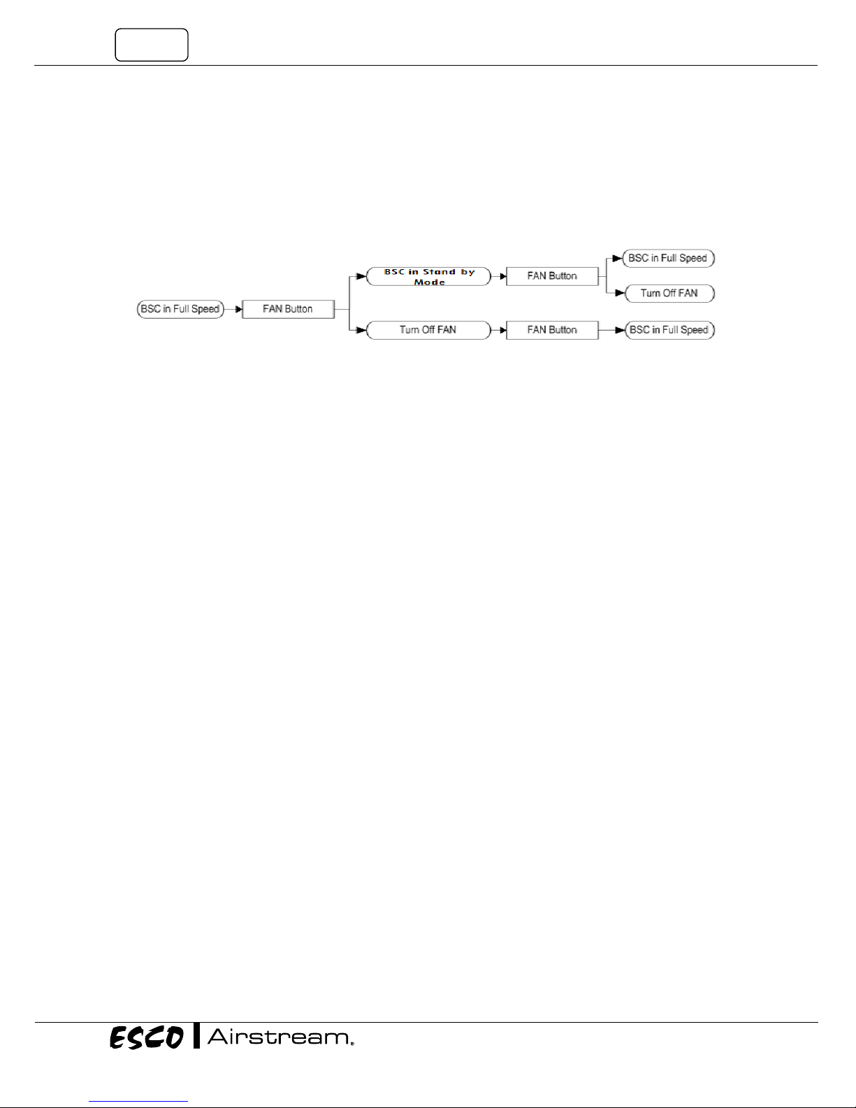
2.6. Standby Mode (Half Speed)
In Standby Mode, the blower speed is greatly reduced resulting in less power consumption. This mode is
typically used during the night to maintain basic level of containment where the cabinet is not used by the
operator.
The mode can be accessed by pressing the FAN button when the cabinet is in operation. In half speed mode,
the airflow monitor is disabled and only the FAN button is operational, while other buttons are interlocked.
11
Chapter 3 - Basic Cabinet Operation
3.1. Sash Window Operation
3.1.1. Sash Window State
Sash is fully open
Blower can be active
Fluorescent lights can be used
Unsafe working condition
Sash is in safe position
Blower can be activated
Fluorescent lights can be used
Safe working condition
Figure 3.1. Sash window positions.
Sash is fully closed
Blower can’t be activated
Fluorescent lights unusable
3.1.2. Operating Motorized Sash Window (Only for BSC with motorized sash window)
The motorized sash uses a “push and hold” mechanism, so if you remove your finger from the button the sash
will stop immediately – this is a safety feature to control the closure and prevent anything getting trapped in
the aperture as the sash descends.
Lower Sash from Fully Open Position
When the sash is fully open, pressing the down button and holding it will cause the sash to move to the Safe
Height setting and stop. If the fluorescent lights are on as the sash descends, they will stay on as long as the
sash stops in the Safe Position. If you release the button before the sash has reached Safe Position the lights
will switch off automatically.
Lower Sash from Safe Height Position
When the sash is at safe operating height, pressing the down button and holding it will cause the sash to move
down to the fully closed position and stop. If the fluorescent lights are on as the sash descends, they will
switch off automatically as soon as the sash is fully closed. If you release the button before the sash has
reached the fully closed position, the lights will switch off automatically.
Raise Sash from Fully Closed Position
When the sash is fully closed, pressing the up button and holding it will prompt the user to input the password
to turn on the fan. If the password is correct, the fan will turn on if it was on and the sash will move up to the
Safe Height setting and stop.
Class II Biological Safety Cabinets

12
Raise Sash from Safe Height Position
When the sash is in safe operation position, pressing the up button and holding it will cause the sash to move
up to the fully open position and stop. If the fluorescent lights are on as the sash rises, they will stay on as long
as the sash is allowed to fully open. Stopping the sash midway will cause the lights to switch off automatically.
3.1.3. Using Sash Window
• The sash window should be fully closed when the cabinet is not in use. This helps to keep the work
zone interior clean.
• The sash window should always be at the normal operating height at all times when the cabinet is in
use. Even if the cabinet is left unattended, while the blower is on, the sash window should never be
moved from the normal operating height, unless during loading or unloading of materials/apparatus
into the cabinet.
• The alarm will be activated whenever the sash window is moved from the normal operating height.
• Whenever the sash window is moved to the correct height from a higher or lower position, the light
will automatically be turned on as a signal to the user.
• The sash window may be opened to its maximum position for the purpose of loading/unloading of
materials/apparatus into/from the cabinet. When the sash window is fully opened, the alarm sound
may be muted by pressing MUTE button but the alarm will automatically sound again after 30
seconds (default is 30 seconds but can be set up to 5 minutes) to remind the user that it is not safe to
work in the cabinet and the light will be turned on to facilitate cleaning.
3.2. Starting and Shutting Down the BSC
3.2.1. Turning on the BSC
1. Raise the sash to the indicated normal operational height (READY state). The lamp will turn on when
this height is reached.
Note: When Quickstart mode is selected, fan will turn on as well, without pressing the fan button.
2. Turn on the fan by pressing the FAN button. Input the Fan PIN if asked (if PIN ≠ 0000). This will start
the warm up procedure (default: 3 minutes). All buttons are disabled during warm up period.
3. The BSC is ready for work.
3.2.2. Turning off the BSC
1. Turn off the fan by pressing the FAN button. Input the Fan PIN if asked (if PIN ≠ 0000). This will start
the post purge procedure (default: 0 minute). All buttons are disabled during post purge period.
2. Lower the sash to the fully closed position (the display will show UV MODE). The sash can be lowered
immediately after turning off the fan as it will not interrupt the post purge procedure.
Note: When Quickstart mode is selected, fan will turn off without pressing the fan button.
3. Turn on the UV lamp (when present) to decontaminate the work area by pressing the UV button.
Leave the UV lamp on to make sure the decontamination is done effectively. The UV lamp can only be
turned on after the post purge procedure is finished.
3.3. Working in the BSC
• Allow the BSC to purge any contaminant by allowing the blower to operate for at least 3 minutes
before and after using the BSC (see Section 2.2.1.5 and 2.2.1.6 of this manual for more information).
• Wear appropriate personal protective equipment (PPE) determined by your risk assessment prior to
working in a BSC.
• Adjust stool height to achieve a comfortable working position.
• Perform surface decontamination on the work area (work surface, back and side walls, UV lamp,
electrical outlets, service fixtures and the inner surface of the sash window) before and after using the
BSC. Filter diffuser should not be wiped to prevent filter damage. Where bleach is used, a second
wiping with sterile water should be carried out to remove any residual chlorine that may corrode
stainless steel surfaces.
 Loading...