

Esco Aeris Series, Aeris-BG384, Aeris-BG086, Aeris-BG4830, Aeris-BG4076 Service Manual

Thank you for purchasing the Esco Aeris Thermal Cycler.
Please read this manual thoroughly to familiarize yourself with
the many unique features and exciting innovations we have
built into cycler. You can view this manual online at
www.escoglobal.com, where you can find many other
resources to help you enjoy many years of productive and
safe use of your Esco equipment.
Service Manual
Thermal Cycler
Version 1.0 Publication Time August, 2009Copyright © 2013 Esco Micro Pte.Ltd. All rights reserved.
Aeris
Chapter 1. Introduction
1.1 Products covered
This manual is applicable and specific to the following ESCO products:-
Aeris Thermal Cycler Aeris-MB with following blocks
Rated voltage (V) 96 wells
100-240V, AC,
50/60Hz
1.2 Basic product information
1.2.1 QUICK VIEW
gradient
block
AERISBG096
30 x 0.5ml +
48 x 0.2ml
mix block
AERISB4830
384 wells
gradient
block
AERISBG384
48 x 0.2ml x2
dual block
AERISBD048
4 In Situ
Slides
AERISB4076

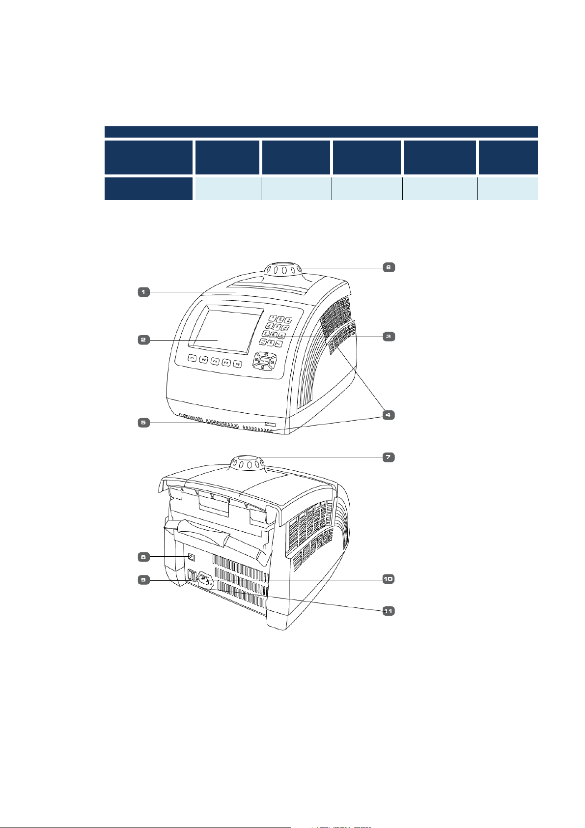
No. Name Description Note
1 Block
2 LCD Screen
3 Keyboard For setting and controlling.
4 Ventilation vent
5 USB interface
6 Hot lid knob Adjust the height of the Knob
7 Unlocking Device Loose the hot lid knob
8 RJ45 interface For PC control and software - Up to 30 Aeris thermal
With hot lid, heat sink and heating&
cooling system.
Display protocol, conditions and
other information during setting and
running.
Blow heat air out through
ventilation vent.
Data transfer between USB and
equipment through USB interface
Five interchangeable blocks
are available for different
requirements.
6.5'' Color LCD Touch Screen
-Don’t block off ventilation
vent
-
Turn the knob counterclockwise before closing the
lid. Note that the knob can be
tightened by turning it
clockwise, and can be
loosened by turning counterclockwise.
If hear click sound at the
beginning of turning the knob
clockwise and counter
clockwise, press the
unlocking device and turn the
knob counter-clockwise for
two rounds to loose the knob
4
upgrades cyclers can be connected and
9 Power Switch Turn the equipment ON/OFF. 10 Power Socket Connect power supply. -
11 Fuse Socket
Install fuse in the socket to protect
equipment from over-current.
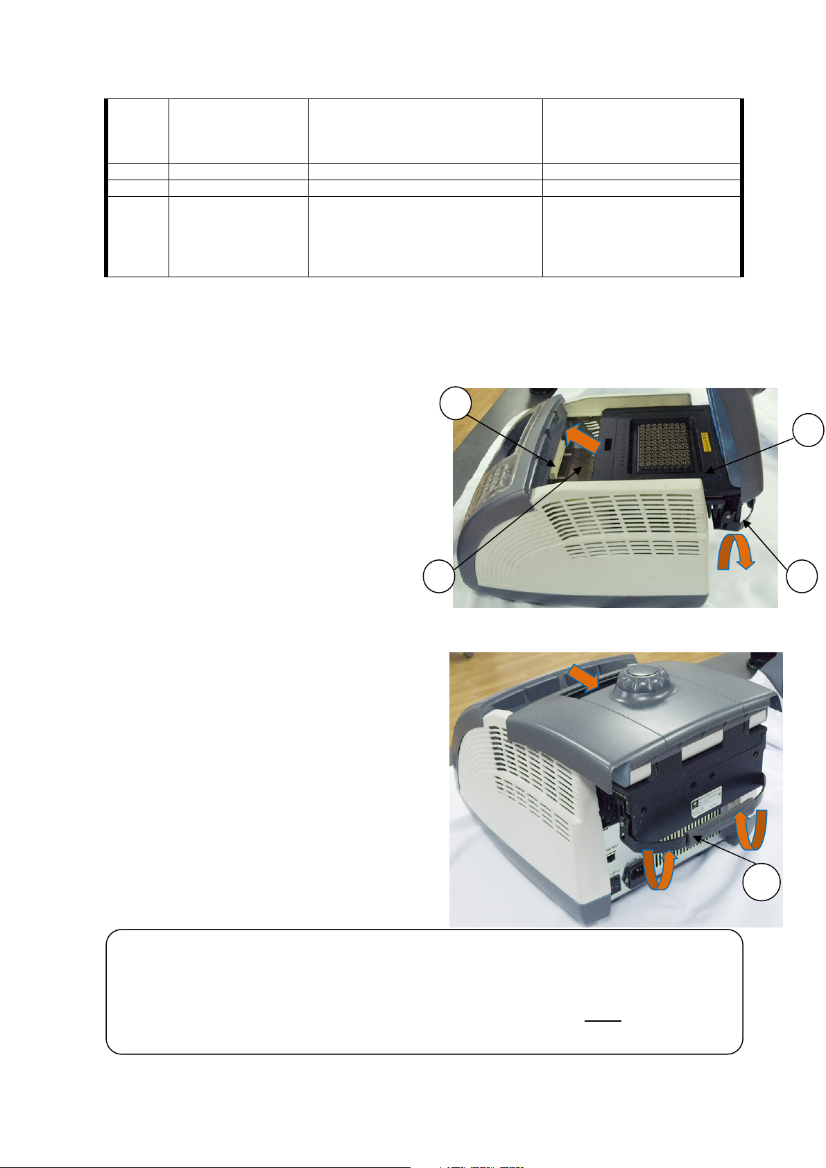
1.2.2 Installing your instrument
Install and Remove the block as follows:
1.2.2.1 Installation:
• Place the block (1) into the housing well (2) and
push it slowly forwards until a connection between
the block socket and the main unit’s connection
plug (3) is achieved.
• Press the locking handle (4) downwards, the block
will move forward automatically until you hear the
click sound, which means the block is installed
successfully.
• Do not force!
1.2.2.2 Removing the Block
• Turn off the power supply.
• Uplift the locking handle (4), the block will move
backward a bit.
• Pull the locking handle to move block gently
towards the rear of the main body.
• Remove the block from the main body.
Note: • Turn off the power supply before installing block.
• When installing the block, pay close attention to pushing the block slowly and gently ; or the
main unit’s connecting plug may be damaged.
• When uninstalling the block, please pull the block from the block bath gently. Do not tilt the
block or the connection plug may break.
controlled by normal
computer through RJ45
interface.
The fuse specifications are as
follows: 250V 8A, 5×20. Fuse
should be replaced by one
that complies with these
specifications.
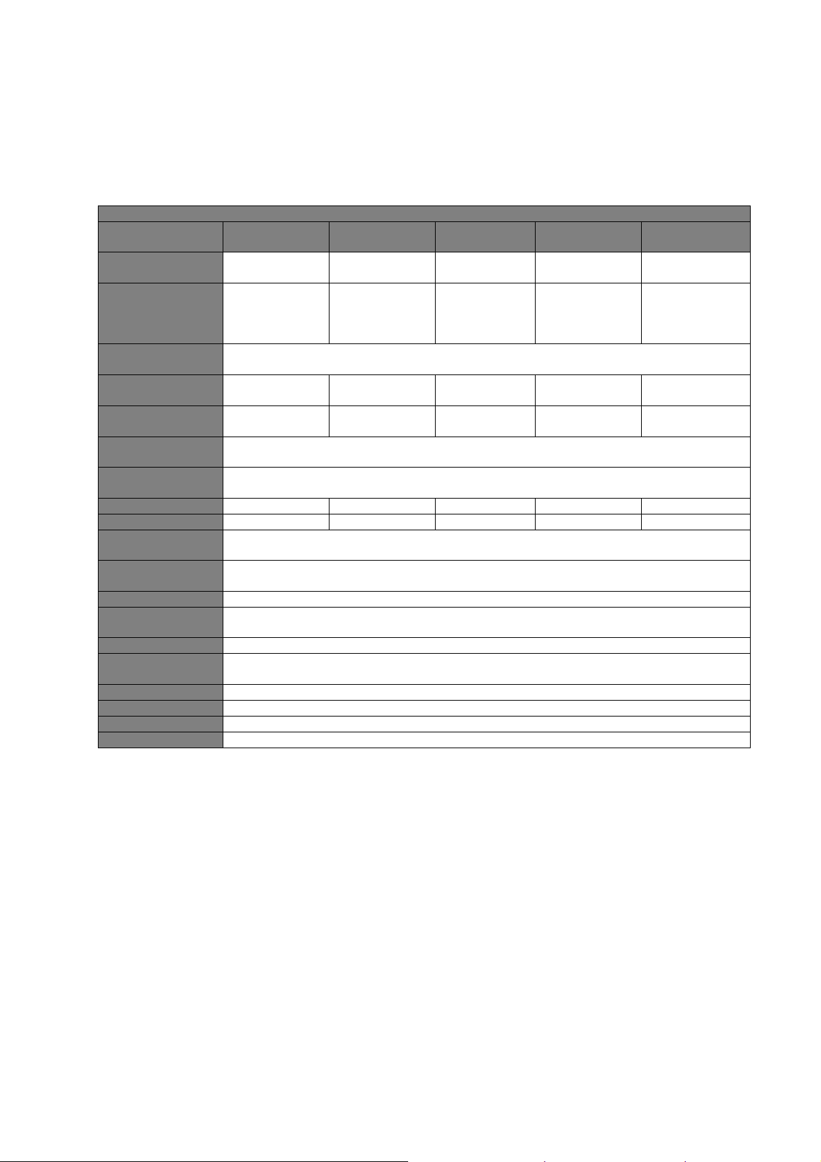
General Specifications, Aeris Thermal Cycler
Block Code
AERIS
-
BG086
AERIS
-
B4830
AERIS
-
AERIS
-
BG384
AERIS
-
B4076
Sample Capacity
Temperature
Max. Heating
Max. Cooling
Temperature
Temperature
Max. Gradient
Min. Gradient
Hot Lid Temp.
Temp. Control
Display
Instrument
PC Interface
Dimensions
Weight (kg)
Power Supply
Fuse
Warranty
1.2.3 Technical specification summary table
48 × 0.2ml + 30
0.2 ml tubes
0.5 ml tubes
4 x 12 strips
Applied
Consumables
Range
96 × 0.2ml
0.2ml tubes
96 micro plate
12 x 8 strips
8 x 12 strips
× 0.5ml
BG384
384 wells
384 micro
plate
4ºC ~ 105ºC
48 × 0.2ml + 48
× 0.2ml
0.2ml tubes
6 x 8 strips
4 slides
4 slides in situ
plate
Uniformity
Accuracy
range
Mode
Memory
(W x D x H)
Rate
Rate
4.0ºC / sec 2.8ºC / sec 2.8ºC / sec 4.0ºC / sec 1.8ºC / sec
4.0ºC / sec 2.8ºC / sec 2.8ºC / sec 4.0ºC / sec 1.8ºC / sec
≤0.2ºC
≤0.1ºC below 50 ºC
30ºC - 30ºC - -
1ºC - 1ºC - -
30ºC ~ 110ºC
Block mode or Tube mode
6.5” Color LCD Touch Screen
Up to 250 programs, unlimited with USB flash drive
RJ45 & USB port
306mm x 386mm x 295mm (WxLxH)
10
100-240 V / 50-60 Hz 600W
250V 8A ø5 × 20
3 years on main body, 2 years on blocks
1.3 Security Notes
i. Turn the power OFF and unplug the power cord before performing any procedure.
ii. Please read all the instructions thoroughly before maintenance. Always follow this
service manual. Keep this service manual well for future reference and review it as
necessary.
iii. Engineers must inspect and ensure operation of the equipment is completely back to
normal after maintenance.
1.4 Guidance
Pay attention on the following before hand.
i. Investigate :-
Situation of the equipment as operating
Previous maintenance record
Symptom of the failure
Hardware environment
Structure of the equipment
Years of the equipment be used
ii. Check power supply.
iii. Check installation of the equipment.
iv. Clean internal of the equipment to eliminate failures caused by dust, dirt, redundant
solder, welding oil.
v. Read all the instructions thoroughly before maintenance to ensure full understanding.
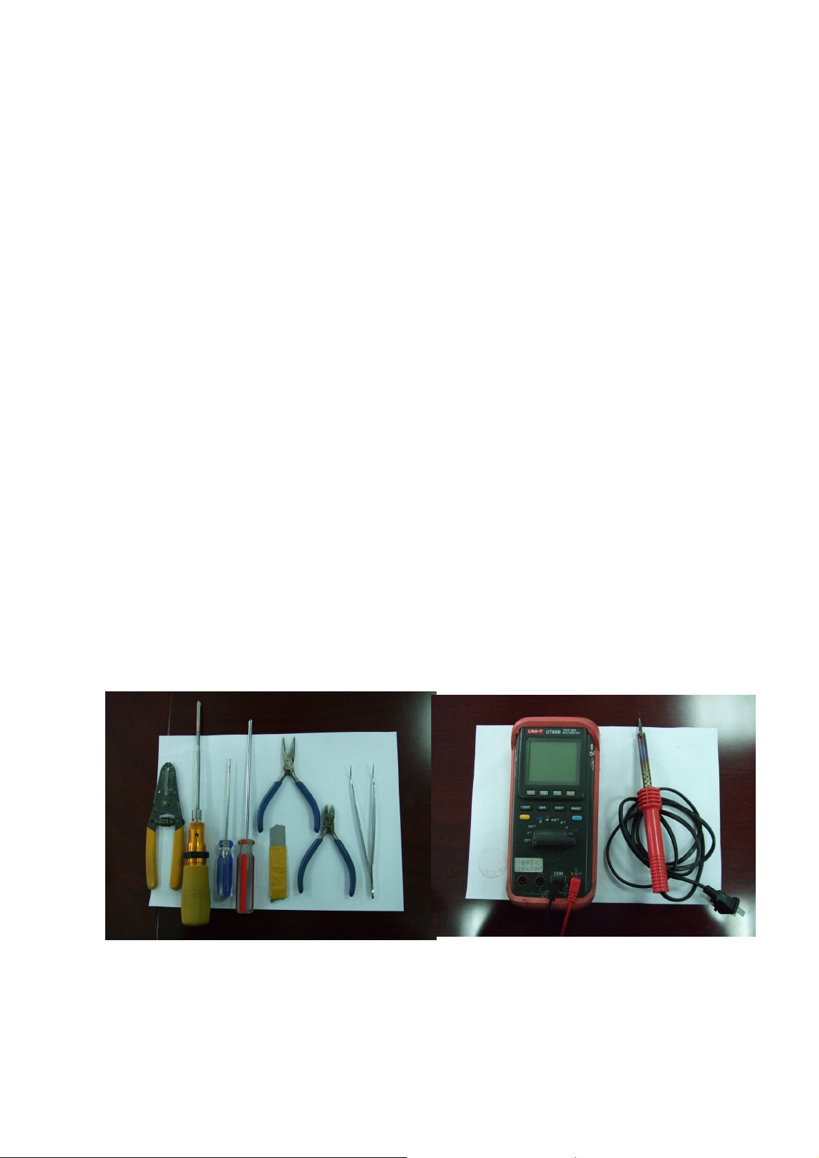
1.5 Maintenance tools
• Wire-stripping pliers, wire stripper
• Torque screwdriver Φ3
• Word screwdriver Φ2
• Cross screwdriver Φ3
• Sharp nose pliers, diagonal cutting nippers
• Pen knife
• Tweezers
• Multimeter
Besides, a multi-channel temperature acquisition device is needed for temperature uniformity and
accuracy testing.
Chapter 2 Service Procedures
2.1 Assemble and disassemble the main body
2.1.1 Assemble procedure
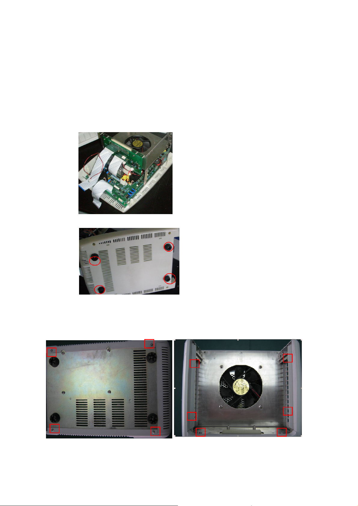
• Assemble the PCB board, power supply and fan with the stainless steel stand.
Put the whole part in the bottom casing and make sure the part is fastened by the
buckle of the bottom casing. Refer to Fig. 1
• Tighten the four screws to fix the rubber feet with bottom casing. Refer to Fig. 2
2.1.2 Disassemble procedure
• Remove the screws as showed in the red square. Take down the left and right
board. Refer to Fig 3, and then you can see the whole main body structure
without the cover(Fig 4)
Fig. 1
Fig 2
Fig 3
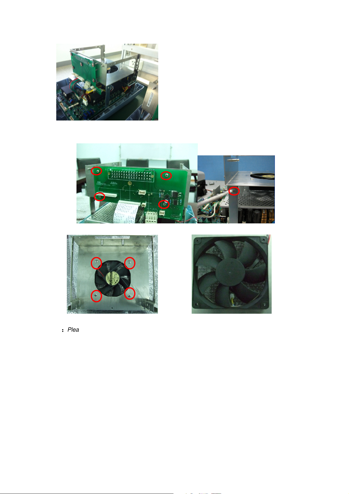
Fig 4
• Unplug all the connectors. Remove the screws in the interface (connector) board.
As Fig.4 and 5
• Remove the screws as Fig 5, and take out the old fan and replace a new fan
Fig 5 Fig 6
Notes
::::
Please note the air flow direction of the fan and the polarity of the connection wire when
replacing the fans. Please mark them to avoid forgetting the correct sequence and make sure the
connection is secure.
2.2 LCD Replacement
Remove the front cover and see the CPU control board as Fig.7

LCD contrast
adjustable screw
Fig.7
Note: A small brass screw on the resistor. Rotating the knob clockwise will brighten the display.
Rotating the knob anti-clockwise will darken the display.
Remove the screws as Fig.8, and then remove the CPU control board.
Fig.8
Remove the screws and get the LCD and LCD control board which are combined into
one part. As Fig.9 and Fig.10
Fig.9 Fig. 10
2.3 Key Pad replacement
Remove the screws as Fig.8 above, and then remove all screws as Fig. 11.
 Loading...