

Esco 10439 Operating Instructions & Parts Manual
Air Actuated
Hydraulic Jacks
Operating Instructions & Parts Manual
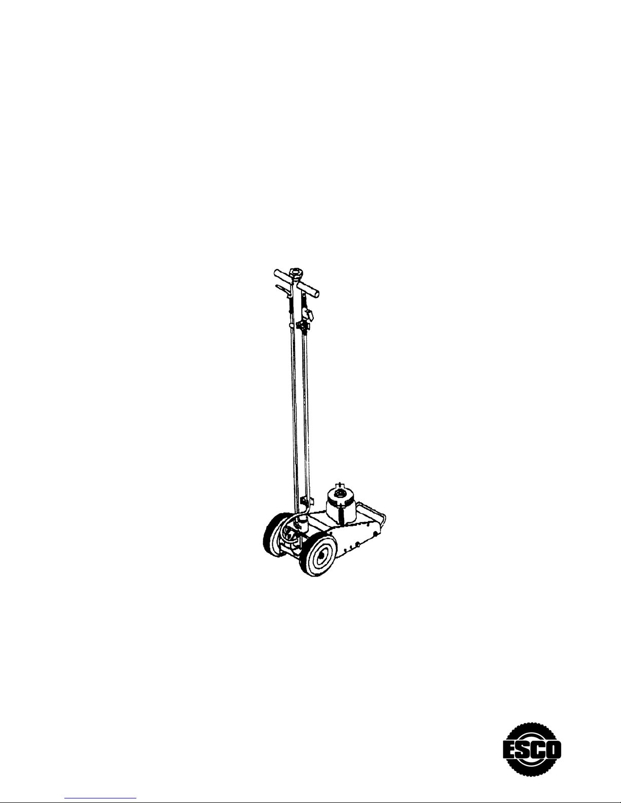
Model 10439
Capacity 44 Ton
Save these instructions. For your safety and the safety of others around you, read carefully before attempting
to assemble, service or use your jack. Observe all safety and warning information. Always wear safety glasses
when operating this product. Failure to comply with the information contained within could result in severe, even
fatal injury and/or property damage.
PRODUCT DESCRIPTION
ESCO Air Actuated Hydraulic Bottle Jack is designed for lifting, but not sustaining, load ranging up to 44 tons
(10434). It can be used vertically or angled to 5 degrees from vertical position. After lifting, loads must be
immediately supported by appropriate means. This model(10434) is equipped with a 3-position handle lock to
aid in proper saddle/lift point alignment. To further aid positioning, 10434 is equipped with large rubber, pivot
wheels. This jack is not recommended for use in lifting or positioning houses and/or other building structures.
This jack comply with applicable ASME / ANSI Standards. Ensure that your air source can dedicate 7.8 CFM @
120 - 200 PSI to each jack operated. To ensure dependable, troublefree operation an air dryer and oiler is
recommended.
SPECIFICATIONS
Model
10439 44 Ton 23" x 14 1/2" 9 ¼” 16 ¼”
Capacity Jack Size( L x W) Min. Height Max. Height
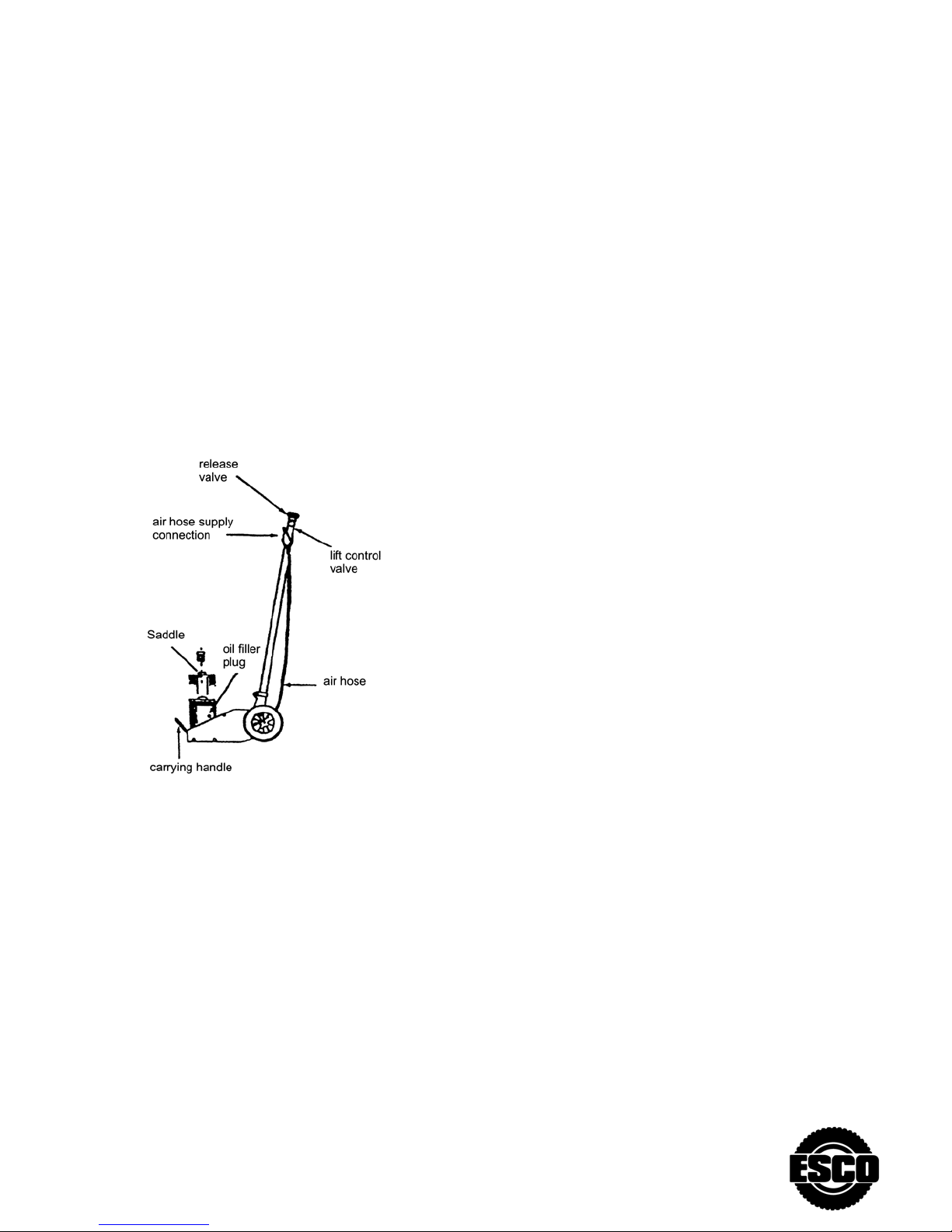
Figure 1 - Model 10439 Nomenclature
BEFORE USE
1.Verffy that the product and the application are
compatible, if in doubt call ~ESCO Technical
Service (800) 352-9852, (352) 754-1117.
2.Before using this product, read the ~owner's
manual completely and familiarize yourself
thoroughly with the product and the hazards
associated with it's improper use.
3.Open the release valve. (counter-clockwise
no more than 2 full turns)
4.With ram fully retracted, locate and remove
the oil filler plug. This will help release any
pressurized air which may be trapped within the
reservoir. Ensure the oil level is just below the
oil filler plug hole. Reinstall the oil filler plug.
5. Inspect before use. Do not use if broken
cracked or damaged parts are noted.
6. Pour a teaspoon of good quality, air tool
lubricant into the air supply inlet of the lift
control valve. (See Illustration) Connect to air
supply and operate for 3 seconds to evenly
distribute
7. Check to ensure that jack rolls freely (if so equipped) and that the air pump operates smoothly before putting
into service. Replace worn or damaged parts and assemblies with ESCO Authorized Replacement Parts only.
8. This product is fitted to accept the popular ¼” NPT air nipple. When installing 1/4" NPT nipple of your
choice, ensure that thread tape or compound is used when servicing connections.
OPERATION
Lifting
1. Assemble handle, use OIPM illustration as
guide, connect to adequate air source.
2. Secure the load to prevent inadvertent shifting
and movement.
3. Position the jack near desired lift point.
4. Close the release valve by turning the handle
mounted knob, clockwise firmly.
CAUTION: DO NOT USE A SADDLE
EXTENDER WHEN USING THIS PRODUCT, LIFT
ONLY ON THE MANUFACTURER'S
RECOMMENDED LIFT POINTS AND IN
ACCORDANCE WITH THE PUBLISHED
GUIDELINES IN YOUR VEHICLE OWNERS
MANUAL. ALWAYS USE JACK STANDS TO
SUPPORT THE LOAD IMMEDIATELY AFTER
LIFTING.
5. Squeeze the lift control valve until saddle
contacts load. Check to ensure proper
saddle/lift point alignment. To end cycle, simply
release the grip on the lift control valve.
NEVER WIRE, CLAMP OR OTHERWISE DISABLE
THE LIFT CONTROL VALVE TO WORK BY ANY
MEANS OTHER THAN BY USING THE
OPERATORS HAND.
6. Raise load to desired height, then immediately
transfer the load to appropriately rated support
devices such as jack stands.
WARNING
THIS IS A LIFTING DEVICE ONLY. IT IS
DESIGNED TO LIFT PART OF THE TOTAL
VEHICLE (ONE WHEEL OR AXLE). ALWAYS
WEAR SAFETY GLASSES WHEN USING THIS
EQUIPMENT. CENTER LOAD ON SADDLE
BEFORE LIFTING. NEVER WORK ON, UNDER OR
AROUND LOAD UNTIL IT IS PROPERLY
SUPPORTED. TRANSFER THE LOAD
IMMEDIATELY TO APPROPRIATELY RATED
JACK STANDS. DO NOT USE THIS PRODUCT
FOR ANY PURPOSE OTHER THAN THAT FOR
WHICH IT WAS INTENDED. IT IS OWNER'S
RESPONSIBILITY TO KEEP LABELS AND
INSTRUCTIONAL MATERIAL LEGIBLE AND
AVAILABLE. REPLACEMENT LABELS AND
MANUALS ARE AVAILABLE FROM THE
MANUFACTURER. FAILURE TO HEED THESE
AND ALL OTHER WARNINGS PERTAINING TO
THIS PRODUCT CAN RESULTIN SUDDEN LOSS
OF LIFTED LOAD RESULTING IN DEATH,
PERSONAL INJURY OR PROPERTY DAMAGE.
Lowering
1. Raise load enough to carefully remove jack
stands,
2. Slowly turn handle mounted release valve
knob, counter-clockwise, no more than 1/2 turn.
If load fails to lower, carefully transfer the load
to another lifting device and stands. Carefully
remove affected ~jack(s) and stands. Carefully
remove jack, again turning the release valve,
slowly, no more than 1/2 full turn.
WARNING
BE SURE ALL TOOLS AND PERSONNEL ARE
CLEAR BEFORE LOWERING LOAD.
DANGEROUS DYNAMIC SHOCK LOADS ARE
CREATED BY QUICKLY OPENING AND CLOSING
THE RELEASE VALVE AS THE LOAD IS BEING
LOWERED. THE RESULTING OVERLOAD MAY
CAUSE HYDRAULIC SYSTEM FAILURE WHICH
COULD CAUSE SEVERE PERSONAL INJURY
AND/OR PROPRTY DAMAGE.
3. After removing jack from under the load,
ensure ram is fully lowered to reduce
exposure to rust and contamination.
 Loading...