

Page 1

User’s Guide
For
Air Hydraulic Jack
Model 10405 (25-2)
Page 2

User's Guide for Air-hydraulic Jack
Model 10405 (25-2)
WARNINGS – SAFE USAGE INSTRUCTION
1. This is a lifting device only.
Do not move or dolly the load while on the jack. The load must be supported immediately by other appropriate means.
2. Do not over load. Over loading can cause damage to or failure of the jack.
3 Lift only areas as specified by the manufacturer.
4 Do not use more than 2 standard extensions in sequence.
5. This jack is designed for use only on hard level surfaces capable of sustaining the load. Use on other than hard level surfaces can
result in jack instability and possible loss of load.
6. It is recommended that the wheels of a vehicle be chocked.
7 No person should remain in. on, or get bodily under a load that is being jacked or is supported only by a jack.
8 The safety valve being adjusted and sealed by the manufacturer shall not be additionally adjusted.
9. Max mum permissible V mature 17D PSI 12 had
10. Failure to heed these warnings may result in loss of load damage to jack, and/or failure resulting personal injury or property damage
Assembly
When mounting the handle (1) turn the hoses round the bearing tubes of the handle as shown on the detail drawing – Ø6 connection (3) for Ø6 quick
fitting (34) and Ø8 connection (4) for Ø8 quick fitting (36). When the jack has been turned over or upside-down a little oil will come into the hoses and
come out with the pump exhaust.
Oil the mechanical parts before starting up – and regularly thereafter.
Use of the Jack
Lifting: Turn the control valve clockwise until the pump starts. Max capacity at 9,0 bar.
Lowering: Turn the control valve counter clockwise.
The handle can be placed in 3 different positions by pulling the spring loaded release grip handle and tipping the handle into the required position.
Lower the jack after use to protect the lifting cylinder.
Maintenance
Like other pneumatic tools, the air pump of the jack needs oil for lubricating the moving parts. It is recommended to use a built-in air lubricator and water
3
separator on the compressor. If not, inject, with about every 25 lifts, approx. 1 cm
Lubricate at the same time the mechanical moving parts with a few drop of oil. Refill of oil: Screw off the filing plug (28) at the side of the jack to refill.
Correct oil level is to lower edge of the hole for the filling plug with the jack in horizontal position, and the cylinder in lowest position. Quantity of oil: 3,01.
Any good hydraulic oil of viscosity 10° - 32° cST/40° C can be used.
NEVER USE BRAKE FLUID!
Possible faults and how to overcome them
1. The jack cannot lift to maximum height, and the pump runs continuously: Refill the oil tank.
2. The air engine goes slowly: the air filter (33-no 22 of the handle) of the control valve has been blocked and needs cleaning or change.
3. The control valve cannot be turned or goes very slowly, even with pressure on the system. The air supply is very watery and the lubricating
film in the valve has been washed out. Mount a water separator with lubricator on your compressor. Loosen the elbow (35) from the valve, fill
the valve with oil, and use the valve many times without air connection. Oil the jack more frequently.
4. In frosty weather: The jack will not pump: There is too much water in the air supply, which has frozen. Mount a water separator with lubricator
on the compressor. Change the oil in the jack, if water in it.
Apart from the above, faults may arise after intensive use due to worn seals, which must then be replaced by new seals.
Max. PERMISSIBLE PRESSURE: 12 bar – 170 PSI.
Destruction:
When the jack after several years is worn and must be dismantled, the oil must be drained off and legally disposed of.
oil into the air connection, and operate the pump to spread the oil.
Page 3
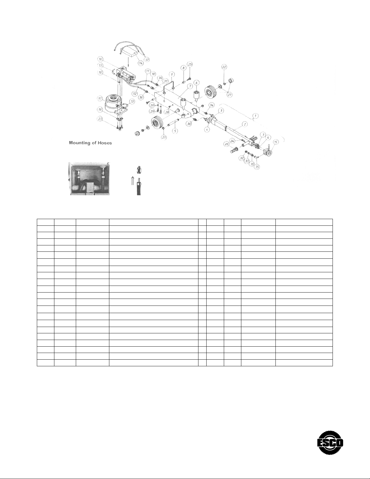
MODEL 10405 (25-2)
Pos. Pcs. No. Description Pos. Pcs. No. Description
44.400.00 25-2, air-hydraulic jack, complete 20 4 02.103.00 Spring washer
1 1 44.001.00 Handle, complete 21 2 02.204.00 Circlip
2 1 44.002.00 Handle 22 2 02.222.00 Circlip
3 1 44.003.00
4 1 44.004.00
5 1 44.005.00 Axle for handle 25 2 02.520.00 Screw
6 2 44.006.00 Extension 26 2 02.390.00 Handle
7 1 44.007.00 Frame 27 2 02.518.00
8 2 44.008.00 Bushing 28 1 02.470.00 Filling plug
9 1 44.009.00 Carrying handle 29 4 02.485.00 Screw
10 1 44-010.00
11 1 44-211.00
12 1 44.012.00
13 1 44-013.00
14 1 44.015.00 Sound absorbing material' 34 2 02-512.00 Quick fitting
15 1 42.000.00 Control valve 35 1 02-515-00 Elbow
16 1 90.725.00 Pump, complete 36 2 02.516.00 Quick fitting
17 1 90.745.00 Cylinder, complete 37 2 02.517.00 Cable ties
18 1 01.000.00 0-ring
19 3 02.102.00 Spring washer
Hose compl. w. ∅ 6 connection
Hose compl. w ∅ 8 connection
Hose, ∅ 6
Oil tube ∅14 complete
Hose ∅8
Hose ∅6 for cylinder
23 3 02.306.00 Screw
24 2 02.324.00 Screw
Wheel ∅l5O
30 1 02-494.00 Gland
31 1 02.498.00 Gland
32 1 02.506.00 Gland
33 1 02-511.00 Filter
Page 4
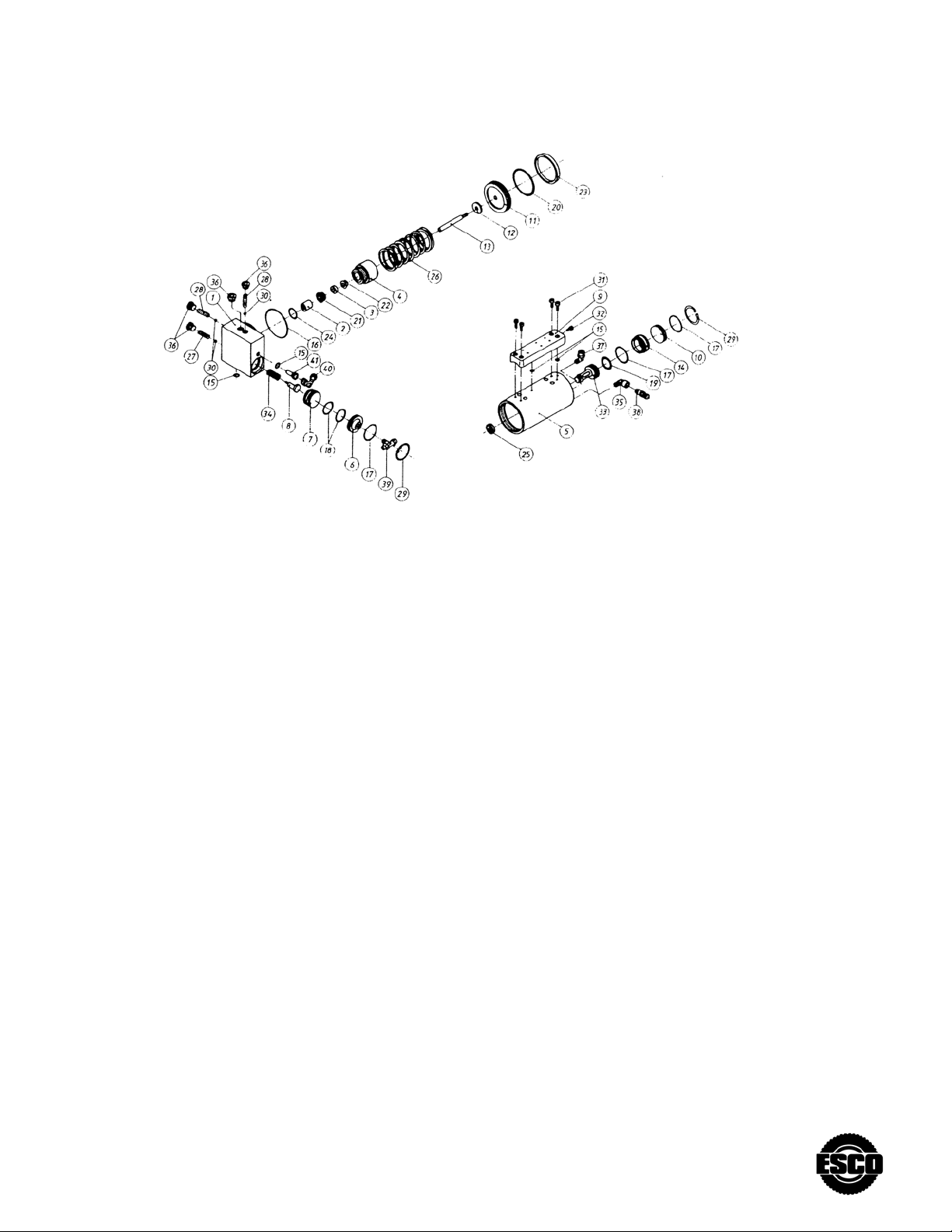
PUMP
Pos. Pcs. No. Description Pos. Pcs. No. Description
90.725.00 Pump, complete 22* 1 01.046.00 O-ring
1 1 90.726.00 Pump body 23* 1 01.126.00 Seal
2 1 90.704.00 Plunger guiding 24* 1 01.245.00 Bondy-seal
3 1 90.705.00 Plunger guiding 25* 1 01.160.00 Seal for change valves
4 1 90.707.00 Packing nut 26 1 02.047.00 Spring
5 1 90.709.00 Air cylinder 27 1 02.047.00 Spring
6 1 90.253.00 Release cover 28 2 02.067.00 Spring
8 1 90.255.00 Release pin 29 2 02.220.00 Circlip
9 1 90.264.00 Exhaust cap 30* 3 02.292.00 Ball Ø6. 5
10 1 90.257.00 Cover for change valve 31 4 02.346.00 Screw
11 1 90.258.00 Air piston 32 1 02.348.00 Screw
12 1 90.259.00 Washer 33 1 02.385.00 Change valve
13 1 90.260.00 Plunger 34 1 02.046.00 Seal
14 1 90.265.00 Cylinder for change valve 35 1 02.425.00 Gland
15* 4 01.000.00 O-ring 36 4 02.483.00 Plug
16* 1 01.007.00 O-ring 37 1 02.495.00 Gland
17* 3 01.034.00 O-ring 38 1 02.503.00 Safety valve
18* 2 01.044.00 O-ring 39 1 02.505.00 T-gland
19* 1 01.045.00 O-ring 40* 1 02.510.00 Gland
20* 1 01.046.00 O-ring 41 1 02.511.00 Filter
21* 1 01.046.00 Seal * 09.032.00 Repair kit
*** Indicate parts included in repair kit. Please always
state model and art no. on your orders for spare parts.
Do always apply original spare parts.
Page 5
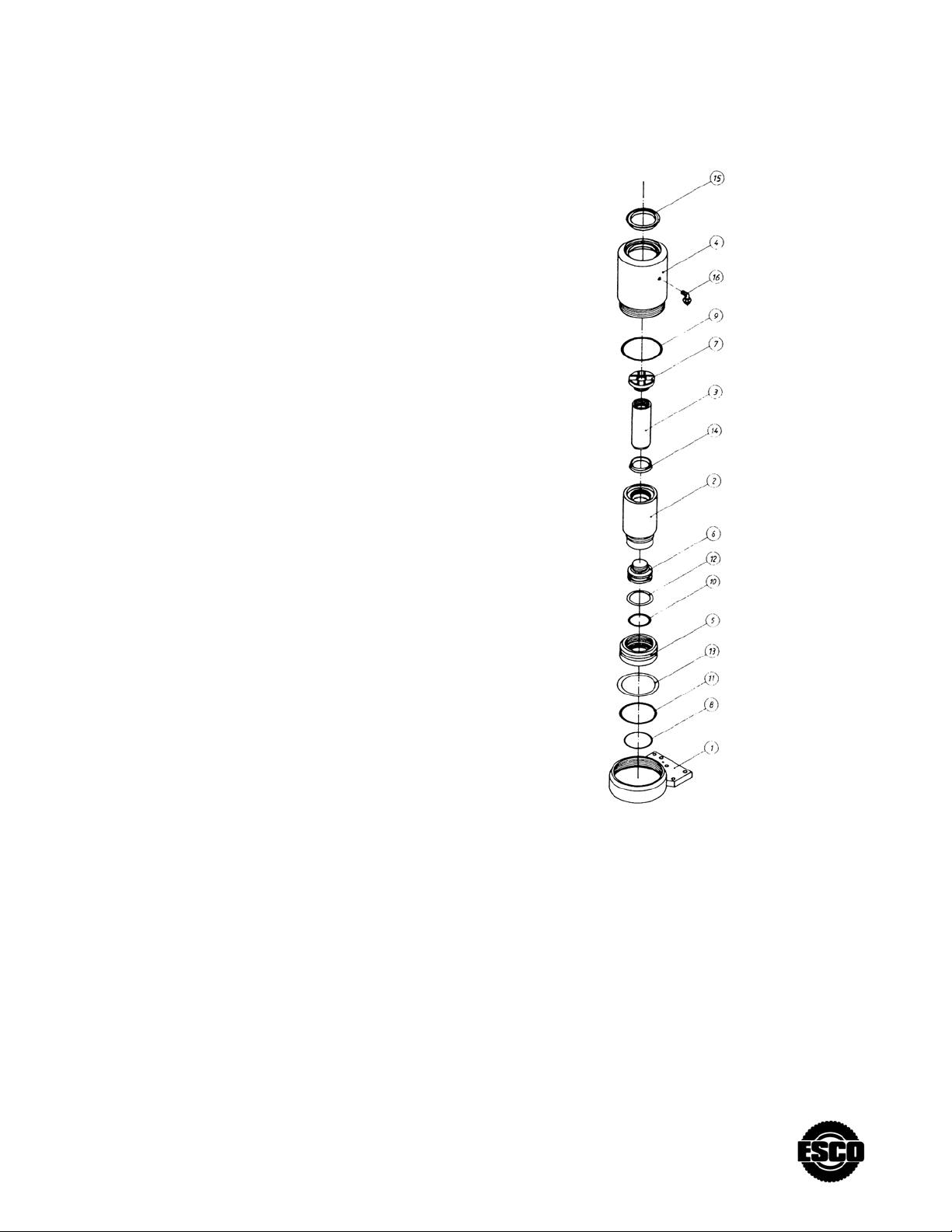
CYLINDER
Pos. Pcs. No. Description
90.754.00 Cylinder complete for model 25-2
1 1 90.746.00 Cylinder bottom
2 1 90.747.00 Middle cylinder
3 1 90.748.00 Piston rod
4 1 90.749.00 Main cylinder
5 1 90.733.00 Piston
6 1 90.734.00 Piston
7 1 90.737.00 Saddle
8* 1 01.031.00 O-rig
9* 1 01.055.00 O-ring
10* 1 01.080.00 O-ring
11* 1 01.081.00 O-ring
12* 1 01.152.00 Back-up ring
13* 1 01.153.00 Back-up ring
14* 1 01.282.00 Scraper ring
15* 1 01.287.00 Scraper ring
16 1 02.493.00 Gland
* 09.033.00 Repair kit
*** Indicate parts in repair kit.
Page 6
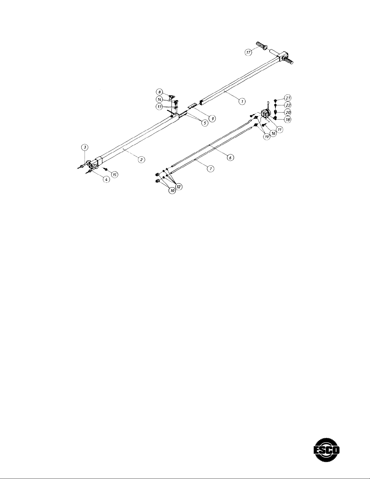
TELESCOPIC HANDLE
Pos. Pcs. No. Description
44.101.00 Telescopic handle, complete
1 1 44.102.00 Extension handle
2 1 44.103.00 Fixed handle
3 1 44.104.00 Hose w Ø6 pipe
4 1 44.105.00 Hose w Ø8 pipe
5 1 44.106.00 Telescopic pipe Ø8
6 1 44.107.00 Telescopic pipe Ø12
7 1 44.108.00 Telescopic pipe Ø12
8 1 44.109.00 Locking hand grip – Locking handle
9 1 40.014.00 Locking hinged joint
10 2 40.021.00 Union nut
11 2 42.00.00 Control valve
12 4 01.056.00 O-ring
13 2 02.111.00 Spring washer
14 2 02.307.00 Screw
15 1 02.315.00 Screw
16 2 02.324.00 Screw
17 2 02.390.00 Handle
18 1 02.515.00 Gland
19 2 02.423.00 Gland
20 1 02.494.00 Gland
21 1 02.506.00 Gland
22 1 02.511.00 Filter
Page 7
OPTIONAL ACCESSORIES
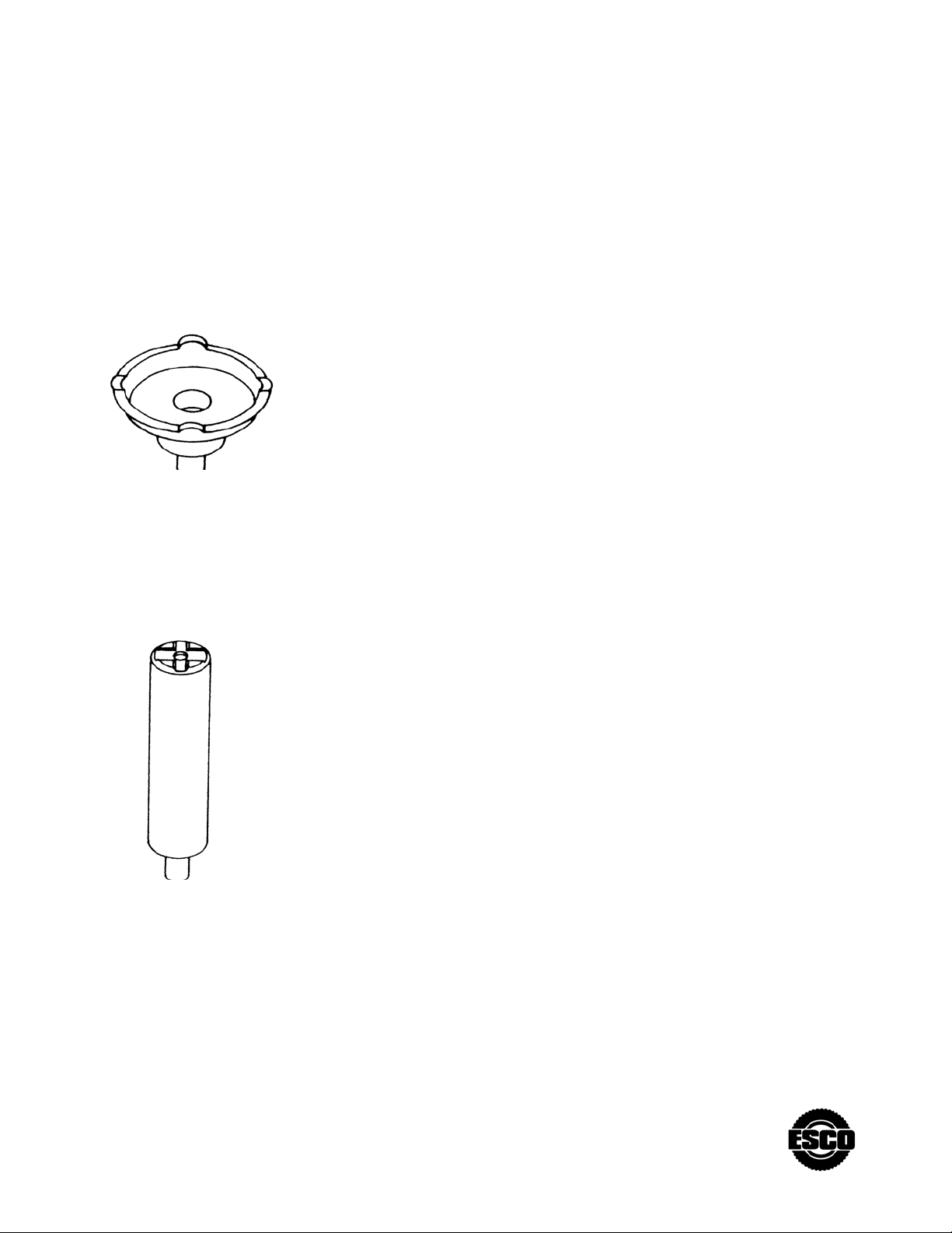
Fw – saddle with diameter of 145mm
no. 10409
F250 Special extension of 250mm no. 10407
 Loading...