

Esco 10006 Operation And Maintenance Manual


OPERATION AND MAINTENANCE MANUAL
For Technical Support and information Contact:
ESCO
15270 Flight Path Drive
Brooksville, FL 34604-6849
Phone: 352-754-1117
Fax: 352-754-4508
E-mail: sales@esco.net
FOR ESCO TORQUE MASTER I 500, TORQUE MASTER I 1000,
TORQUE MASTER I 2000, TORQUE MASTER I 3000, AND TORQUE MASTER I 6000
SQUARE DRIVE PNEUMATIC TORQUE WRENCHES
NOTICE
Series Torque Master I 500, Torque Master I 1000, Torque Master I 2000, Torque Master I 3000, Torque Master I 6000
Pneumatic Torque Wrenches are designed for installing and removing thread fasteners requiring precise high torque during
bolt makeup and maximum torque for bolt breakdown.
ESCO is not responsible for customer modification of tools for applications on which ESCO was not consulted.
WARNING
IMPORTANT SAFETY INFORMATION ENCLOSED.
READ THIS MANUAL BEFORE OPERATING TOOL.
IT IS THE RESPONSIBILITY OF THE EMPLOYER TO PLACE THE INFORMATION IN THIS MANUAL
INTO THE HANDS OF THE OPERATOR.
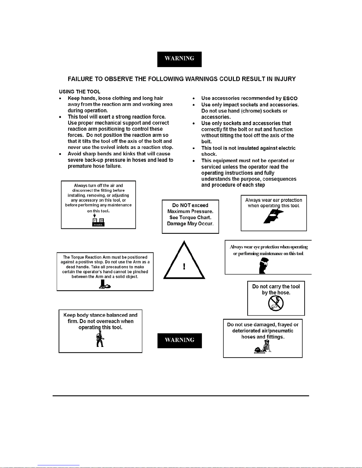
FAILURE TO OBSERVE THE FOLLOWING WARNINGS COULD RESULT IN INJURY.
The Torque Master I tools contain alloy components which may cause a hazard in certain explosive environments.
GENERAL DESCRIPTION OF ESCO TORQUE MASTER I SERIES PNEUMATIC TORQUE WRENCHES
Torque can be adjusted by regulating the amount of airflow to the torque wrench and by manipulating the air pressure regulating valve
at the Filter/Regulator/Lubricator Unit (Torque Master I F/R/L). On top, and airflow volume control is incorporated at the machine
providing an extended torque range. The accuracy of maintaining a selected torque is subject to the stability of your air supply. An
airflow of 25 to 40 SCFM guarantees optimum performance even within a non-protected working environment.
The Torque Master I Series Pneumatic Torque Wrench provides torque settings of up to 6,000 Ft. Lbs, clockwise and counter
clockwise rotation, random positioning of the tool due to its free joint execution.
The use of other than genuine ESCO replacement parts may result in safety hazards, decreased tool performance, and
increased maintenance, and may invalidate all warranties.
Repairs should be made only by authorized personnel. Consult your nearest ESCO Authorized Service Center.
Refer All Communications to ESCO.
NOTICE
OPERATION OF THE EQUIPMENT IN ACCORDANCE WITH SPECIFIED USE
Depending on the working environment and how the Torque Master I Series Pneumatic Torque Wrench is used, local health and
safety regulations may require you wear protective gear (i.e. Ear Protection, Safety Shoes, Hard Hat, Gloves, Coveralls, etc.) In case
external forces are exerted on the equipment, non-compliance with these regulations may result in injury. EAR PROTECTION MUST
BE WORN WHEN OPERATING THIS TOOL. When in continuous use the grip casing will cool down considerably – operator
should wear protective-working gloves as a consequence.

Operation of the Equipment in Accordance with Specified Use – Con’t
1. Inspect, maintain, operate and install the tool in accordance with all applicable standards and regulations (local,
state county, federal, etc.)
2. Do not remove any labels. Replace any damaged labels immediately.
3. Always use clean, dry air at 90 p.s.i.g. (6.2 bar/620kPa) maximum air pressure at the inlet. Higher pressure may
result in hazardous situations including excessive speed, rupture, or incorrect output torque or force.
4. Be sure all hoses and fittings are the correct size and tightly secured.
5. Ensure an accessible emergency shut off valve has been installed in the air supply line, and make others aware of
its location.
6. Install a properly sized safety air fuse upstream of hose and use an anti-whip device across any hose coupling
without internal shut-off, to prevent hose whipping if a hose fails or coupling disconnects.
7. Do not use damaged, frayed or deteriorated air hoses and fittings. Do not paint hoses.
8. Keep clear of whipping air hoses. Shut off the air compressor before approaching a whipping hose.
9. Always turn off the air supply, bleed the air pressure and disconnect the air supply hose before installing,
removing or adjusting any accessory on this tool, or before performing any maintenance on this tool or any
accessory.
10. Do not lubricate tools with flammable or volatile liquids such as kerosene, diesel or jet fuel. Use only ESCO
recommended lubricants.
11. Use only proper cleaning solvents to clean parts. Use only cleaning solvents which meet current safety and health
standards. Use cleaning solvents in a well ventilated area.
12. Keep work area clean, uncluttered, ventilated and illuminated.
Safety Information When Using the Tool
1. When wearing gloves always be sure that the gloves will not prevent the throttle mechanism from being released.
2. Always wear eye protection when operating or performing maintenance on this tool.
3. Always wear hearing protection when operating this tool.
4. Always use Personal Protective Equipment appropriate to the tool used and material worked. This may include
dust mask or other breathing apparatus, safety glasses, ear plugs, gloves, apron, safety shoes, hard hat and other
equipment.
5. Prevent exposure and breathing of harmful dust and particles created by the tool use.
a. Some dust created by power sanding, sawing, grinding, drilling, and other construction activities
contains chemicals known to cause cancer, birth defects or other reproductive harm. Some examples of
these chemicals are:
i. Lead from based paints
ii. Crystalline silica from bricks and cement and other masonry products
iii. Arsenic and chromium from chemically treated lumber
Your risk from these exposures varies, depending on how often you do this type of work. To reduce your
exposure to these chemicals: work in a well ventilated area, and work with approved safety equipment, such as
dust masks that are specially designed to filter out microscopic particles.
6. Keep others a safe distance from your work area, or ensure they use appropriate Personal Protective Equipment.
7. Be aware of buried, hidden or other hazards in your work environment. Do not contact or damage cords, conduits,
pipes, or hoses that may contain electrical wires, explosive gases or harmful liquids.
8. Keep hands, loose clothing, long hair and jewelry away from working end of tool.
9. Power tools can vibrate in use. Vibration, repetitive motions or uncomfortable positions may be harmful to your
hands and arms. Stop using any tool if discomfort, tingling feeling or pain occurs. Seek medical advice before
resuming.
10. Keep body stance balanced and firm. Do not overreach when operating this tool. Anticipate and be alert for
sudden changes in motion, reaction torques, or forces during start up and operation.
11. DO NOT USE THIS TOOL WHEN TIRED, UNDER THE INFLUENCE OF MEDICATION, DRUGS OR
ALCOHOL.
12. Never use a damaged or malfunctioning tool or accessory.
13. Do not modify the tools, safety devices or accessories.
14. Do not use this tool for purposes other than those recommended.
15. Never exceed rated RPM of tool.
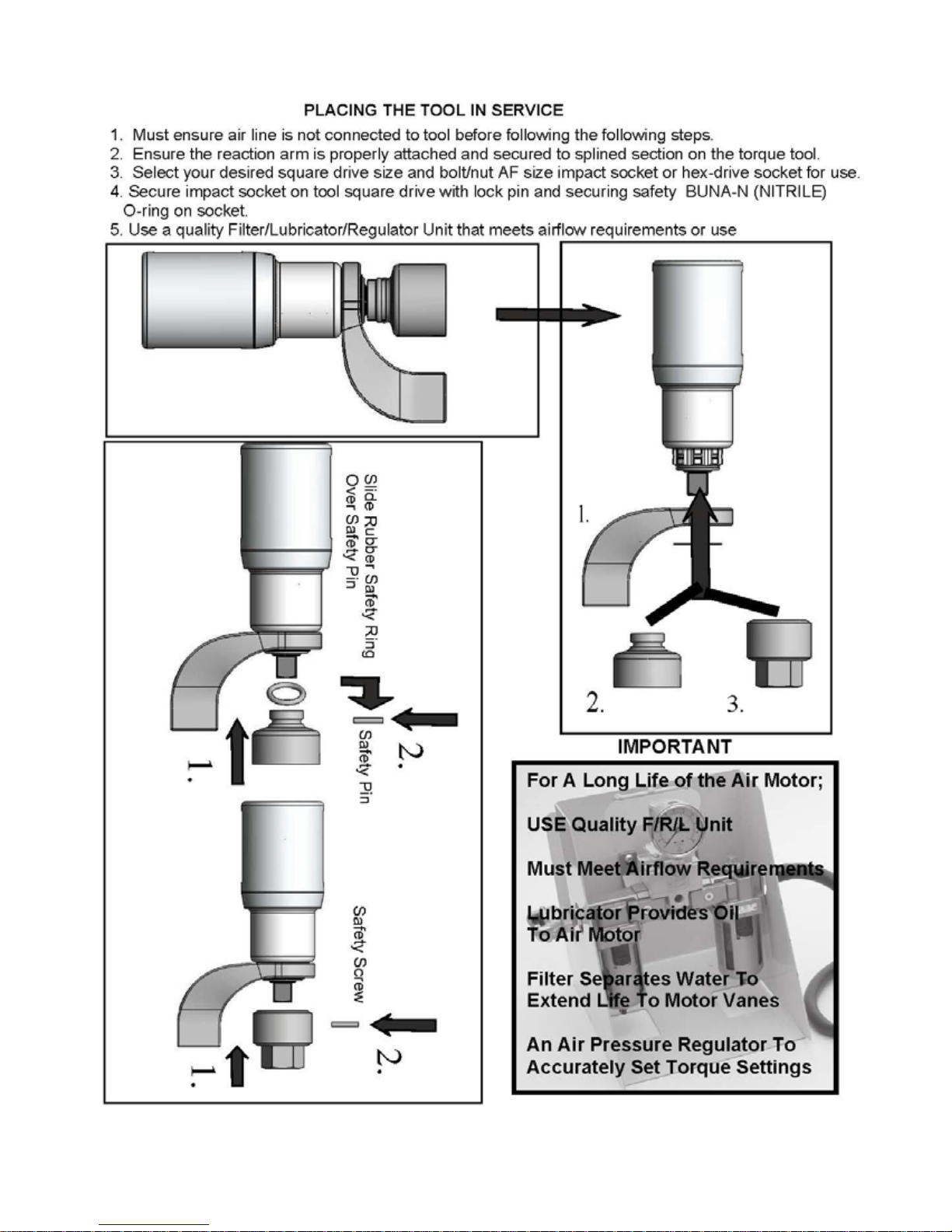
OPERATING PROCEDURES
Setting Torque on Torque Master I Series Torque Wrenches
1. Torque depends on the air pressure exerted on the air motor under load. Adjusting the F/R/L Unit Regulator Knob
initially sets torque. To decrease torque output turn regulator counter-clockwise to lower air flow/pressure. All
Torque Master I are shipped calibrated per ESCO Procedures.
2. Check for Desired Torque Setting for your selected model on the supplied torque chart. On the Torque Master I
F/R/L, adjust air pressure by using the air regulator knob for desired pressure/torque. With the Torque Master I
Series Torque Wrench under load (not on the nut/bolt), press the toggle switch. Once pressure is set for desired
torque output and airflow/pressure, push in on regulator knob to lock unit. While the Torque Master I Series
Torque Wrench is under load, running at free speed (not on the nut/bolt), adjust the Torque Master I F/R/L
pressure at the same time.
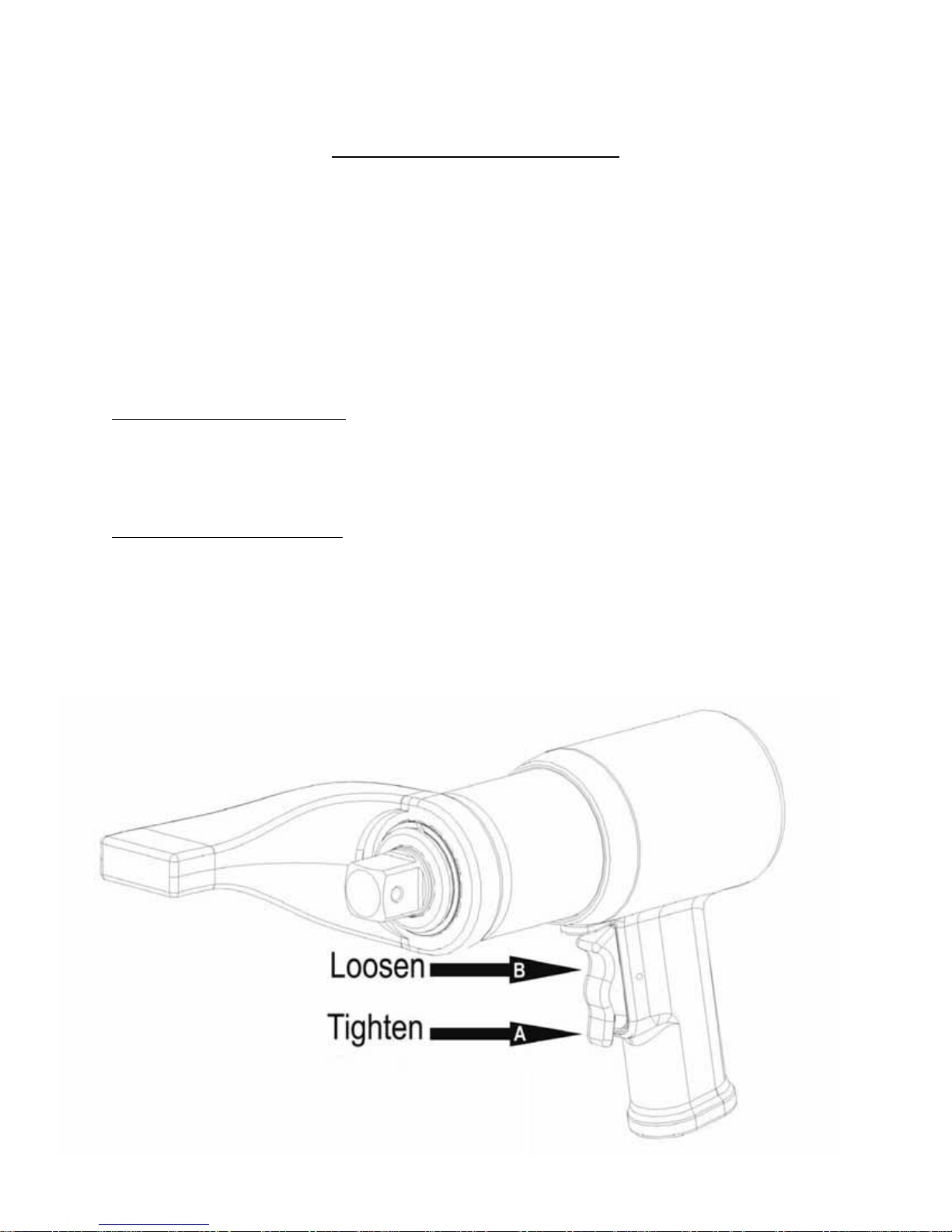
A.
Setting torque for Bolt Tightening
1. Establish the air pressure required using the Torque Calibrated Chart provided with the tool.
2. Push Trigger using tightening Direction per A on below diagram.
3. Adjust the regulator until the correct pressure is shown on the gauge by turning adjustment knob
clockwise.
B.
Setting torque for Bolt Loosening
1. Establish maximum air pressure from the Torque Chart.
2. Push Trigger using loosening Direction per B on below diagram.
3. Set the air pressure the same as with tightening.
 Loading...