

Page 1
630346_0 FS730 Builders and Architects Sheet
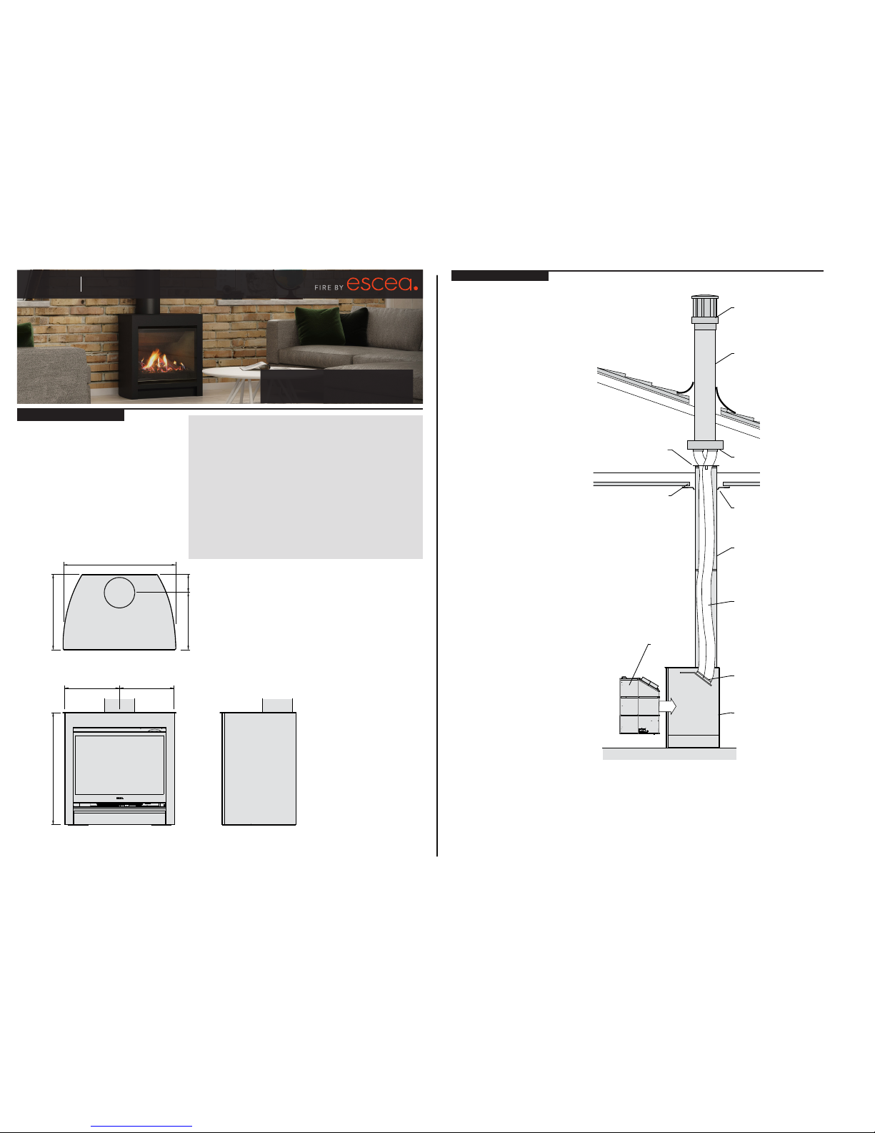
Product Dimensions
All outside dimensions taken from the appliance are
with the standos attached.
FS730
Information Sheet for Builders and Architects
Appliance Information
For further information or specications, visit the
technical section of our website www.escea.com
to view the latest product Installation Manual.
Specications
Heat Output 5-5.6 kW
Star Rating 3-4 stars
Gas Input/Consumption 22-25 MJ/hr
Gas Connection lower right, 1/2” BSP female thread
Gas Type Natural Gas / ULPG (NZ) / Propane (Aus)
Weight 45 kg
Room fan Yes
Flue Type Simpson Duravent Direct Vent (False Chimney)
Flexi Flue (Masonry)
Flue Size 6” mm Outer, 4” mm Inner (Direct Vent)
4” and 3” Flexi Flue (Masonry)
Power Requirement 3 pin earthed 230V power outlet +isolating switch
to be within 1.0m of rear right hand corner of the
appliance.
Smart Heat App Yes
Flue Installation
505mm
735mm*
381mm
124mm
753mm
368mm* 368mm*
*Not including Lid
The freestanding unit and flue system
should be installed prior to the AFSeries fireplace being installed.
□ Place the freestanding unit in the
correct location, complying with
the clearances specified in the previous
section.
□ Remove 2 screws on each side of
the fascia just below the top panel and
pull towards you to remove the fascia.
□ Each corner of the FS730 has
securing holes to fix the FS730 to the
floor.
□ Refer to section C of this installation manual for minimum and maximum flue lengths, restrictor settings
for your installation, and all other flue
information.
□ Run the black Ø230mm flue
liner lengths from the top of the
freestanding unit until it penetrates the
Ø265mm ceiling hole.
□ Use the supplied Ceiling plate for
tidying the internal termination point
of the Ø230mm flue liner.
□ Run the 2x flexible flues down
through the Ø230mm flue liner and
attach it to the Flue Spigot Plate as per
section C of this manual
□ Open the flue liner rodent guard
and close around the flexi flue. Rivet,
screw or cable tie the open end to
prevent it from opening. Bend the two
perpendicular tabs down and screw into
the flue liner using a short self tapping
screw. Note: Take care when installing the rodent guard to not cause damage to the flexi flue.
□ Install flue termination as per section C of this manual
Note: Ensure a power supply is within 1m of the rear of the appliance.
Ceiling Ring
225mm
Flue liner
2x Flexible
flue inner
Coaxial to Colinear
conversion box
Duravent 4x6”
Rigid Direct-vent
flue
Rigid flue
Flexible flue clamped
to Flue SpigotPlate
AF700
Fireplace
FS730 Freestanding
Unit
Flue Liner
Rodent Guard
Ø265 mm
Ceiling hole
Page 2
630346_0 FS730 Builders and Architects Sheet
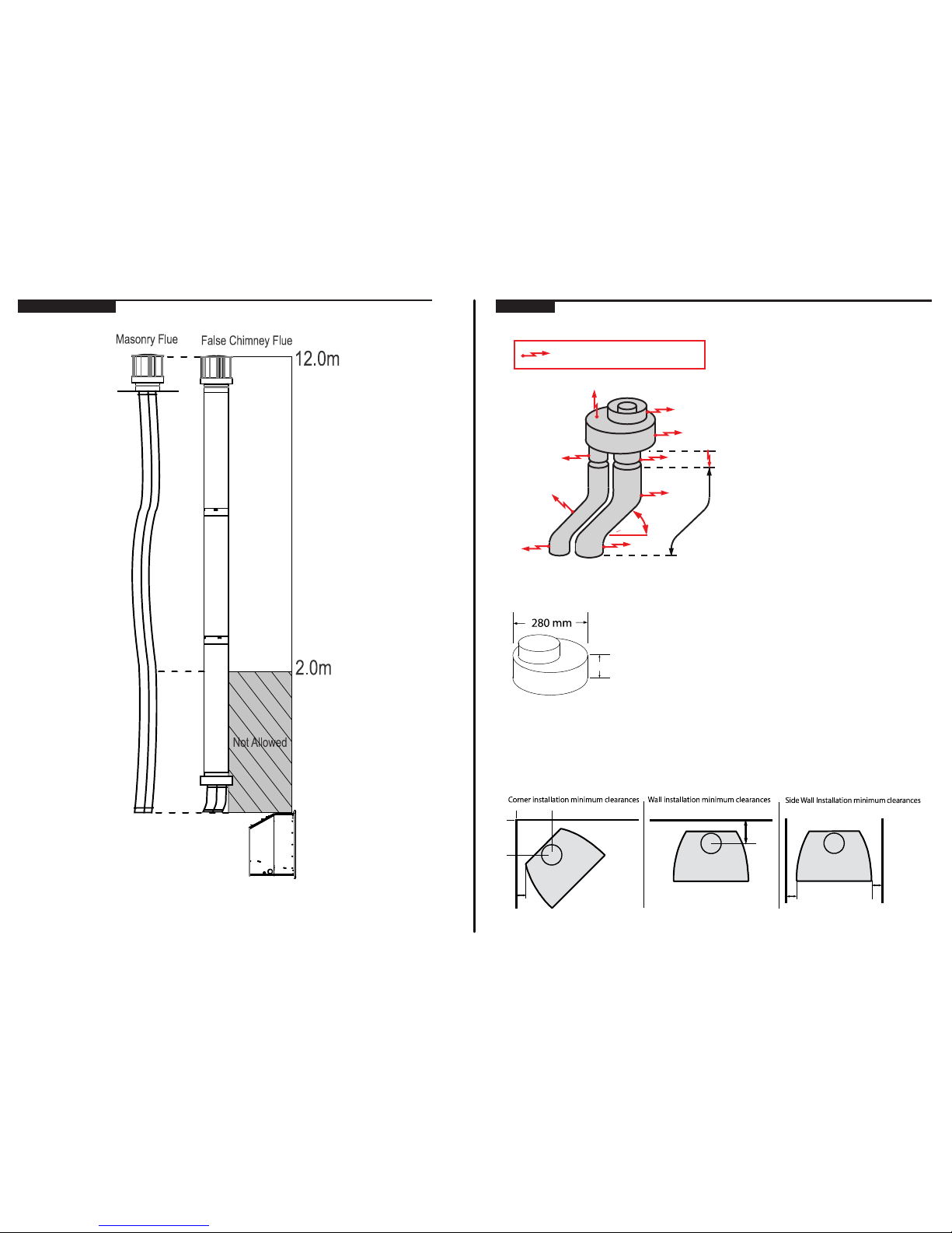
Vertically terminating flue diagram
Flue Information
IMPORTANT : Refer to the installation manual for mandatory clearances from the terminal.
Clearances
Flueing Clearances
25mm
=
Minimum distance to combustibles
50mm 50mm
0mm*
*Note: Underside of converter box can be xed straight onto wooden joists.
**Note: Flexi-Flue must not be run at an angle greater than 45 degrees from
vertical; excluding all appliance built into a freestander kit.
50mm
50mm
>45°**
50mm
Ø75mm Intake
Ø100mm Exhaust
50mm
25mm
25mm
600mm
300mm to
78 mm
Converter Box Dimensions
Hearth and Clearances
A Hearth is not required, however it may be used for decorative purposes or for protection of sensitive flooring. The
hearth should not obscure the front face of the fire.
Do not place items or furnishings ontop of the freestanding fireplace, and ensure soft furnishings do not come in
contact with the freestanding fireplace.
175mm
315mm
50mm
50mm 50mm
 Loading...