

Page 1
630162_2EF5000InstallationGuideR‐emotion‐US
Installation Manual
EF5000 - US
WARNING: If the information in this manual is not followed exactly, a fire or
explosion may result causing property damage, personal injury or loss of life.
- Do not store or use gasoline or other flammable vapors and liquids in the
vicinity of this or any other gas appliance.
- WHAT TO DO IF YOU SMELL GAS:
o Do not try to light any appliance.
o Do not touch any electrical switch; do not use any phone in your
building.
o Immediately call your gas supplier from a neighbour’s phone. Follow
the gas suppliers instructions.
o If you cannot reach your gas supplier, call the fire department.
- Installation and service must be performed by a qualified installer, service
agency or gas supplier.
- Instructions must be left with the consumer and the consumer to retain
them for future reference
WARNING: Improper installation, adjustment, alteration, service or maintenance
can cause injury or property damage. Read the installation, operating and
maintenance instructions thoroughly before installing or servicing this equipment.
WARNING: For Outdoor Use Only.
Page 2
630162_2EF5000InstallationGuideR‐emotion‐US
Important:
The appliance shall be installed in accordance with;
• Local gas fitting and building codes, or in the absence of local codes, with the
National Fuel Gas Code, ANSI Z223.1
• The appliance, when installed, must be electrically grounded in accordance with
local codes or, in the absence of local codes, with the National Electrical Code,
ANSI/NFPA 70. (If applicable)
This appliance must only be installed by an authorized person.
Warning:
The area surrounding the appliance must be clear and free from combustible materials,
gasoline and other flammable vapors and liquids.
This appliance must not be installed or used indoors.
Children and adults should be alerted to the hazards of high surface temperatures and
should stay away to avoid burns or clothing ignition.
Young children should be carefully supervised when they are in the area of the appliance.
Clothing or other flammable materials should not be hung from the appliance, or placed on
or near the appliance.
Any guard or other protective device removed for servicing the appliance must be replaced
prior to operating the appliance.
Installation and repair should be done by a qualified service person. The appliance should
be inspected before use and at least annually by a qualified service person. More frequent
cleaning may be required as necessary. It is imperative that control compartment, burners
and circulating air passageways of the appliance be kept clean.
Do not use this appliance if any part has been under water. Immediately call a qualified
service technician to inspect the appliance and to replace any part of the control system
and any gas control which has been under water.
Under no circumstances should you touch the coals or metalwork during operation.
Contact:
Manufactured by: Escea Ltd, PO Box 5277 Dunedin NZ, Ph: +64 3 478 8220, email: [email protected]
Page 3

630162_2EF5000InstallationGuideR‐emotion‐US
Contents: Page:
Product description 1.0
Power supply 2.0
Creating the cavity 3.0
Cavity Dimensions 4.0
Wall cladding around the fire 5.0
Minimum install height off the ground 6.0
Corner Installations 7.0
Laying gas pipe 8.0
Fixing the fire into the cavity 9.0
Connecting gas pipe 10.0
Connecting the power supply and touch panel 11.0
Testing of touch panel and spark ignition 12.0
Checking operating pressure 13.0
Assembly of stone cartridge 14.0
Fitting the fascia
15.0
Placement of ceramic pebbles 16.0
Operating Instructions 17.0
Maintenance and cleaning 18.0
Replacement Parts 19.0
Page 4
630162_2EF5000InstallationGuideR‐emotion‐US
1.0 Product Description:
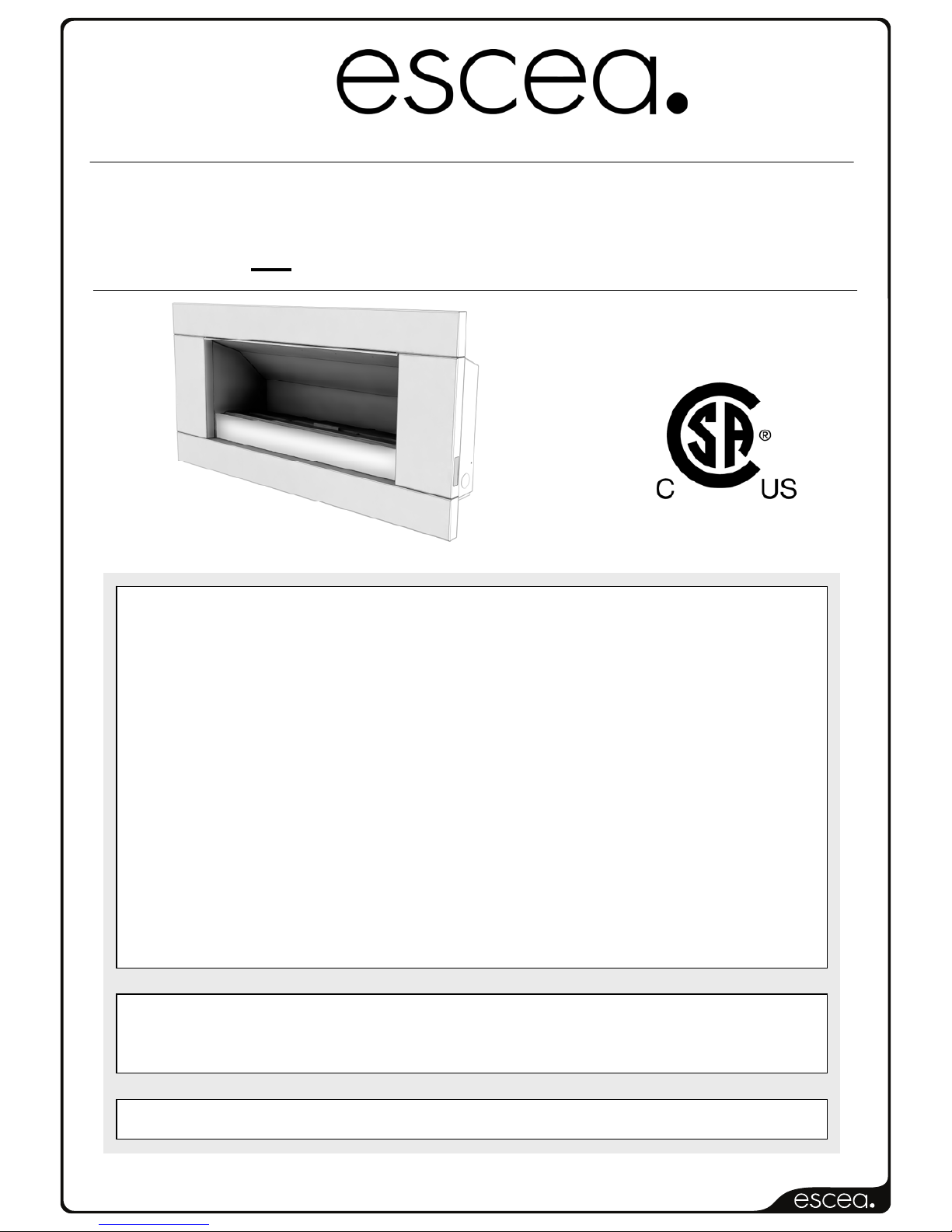
The escea EF5000 flame effect gas fire is designed for outdoor use only.
This appliance requires no flue and must be permanently installed into a cavity.
It may be installed into a timber cavity.
The fire is controlled by the user, from a touch panel that is situated on the lower right hand
side of the stainless steel fascia, or if the ‘wall mount’ option is chosen, the remote will be
situated on the wall near the fire, connected by a cord.
The Data Plate, containing all technical information such as manufacture date, serial
number, gas type, jet size, etc, can be found in the lower right hand side of the fire, below
the firebox. To access this the fascia must be removed.
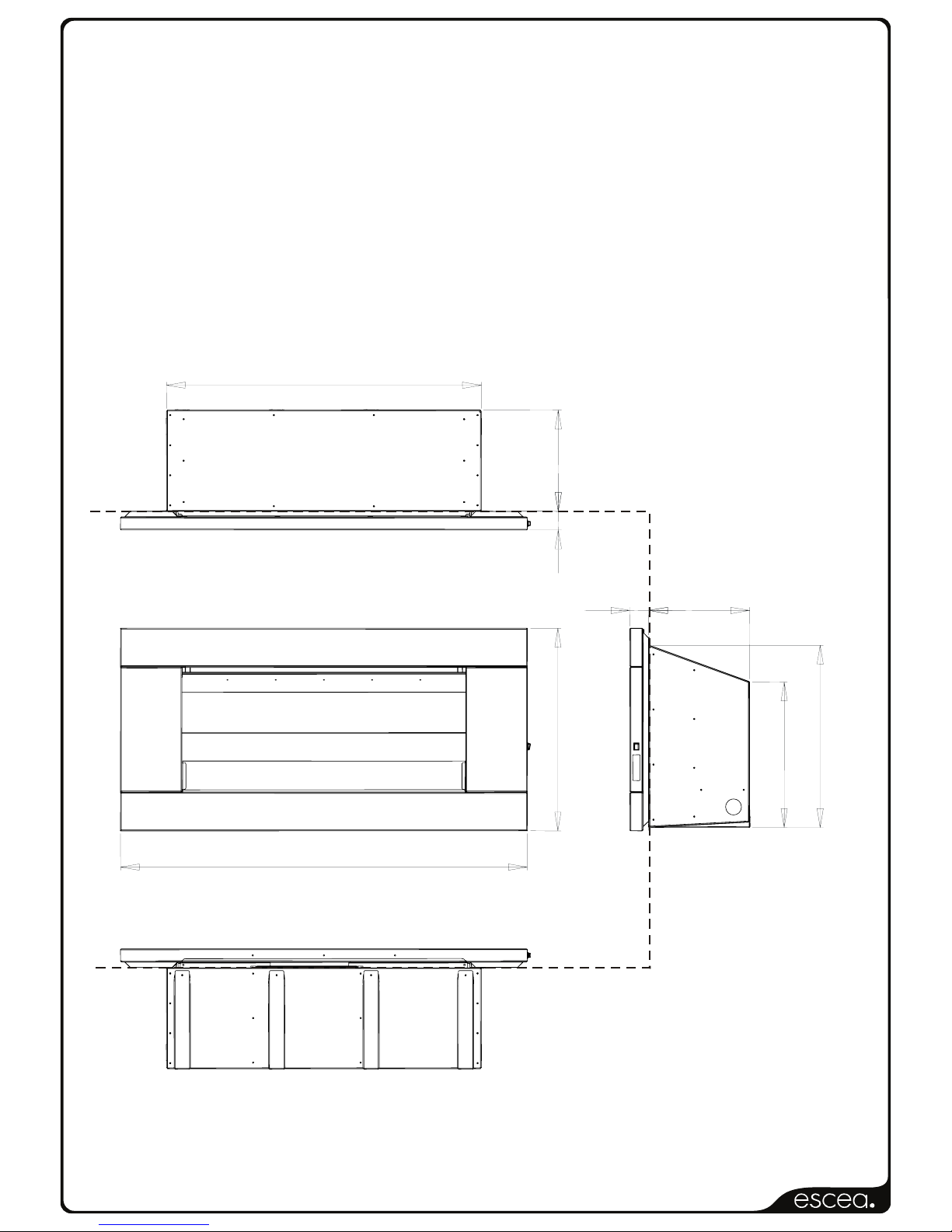
1.1 Product dimensions: (in)
25 3/8 ”
50 7/8 ”
2 3/8 ”
12 5/8 ”
18 3/
16
”
22 13/
16
”
39 3/8 ”
12 5/8 ”
2 3/8 ”
Face of the Wall
Page 5
630162_2EF5000InstallationGuideR‐emotion‐US
2.0 Power Supply:
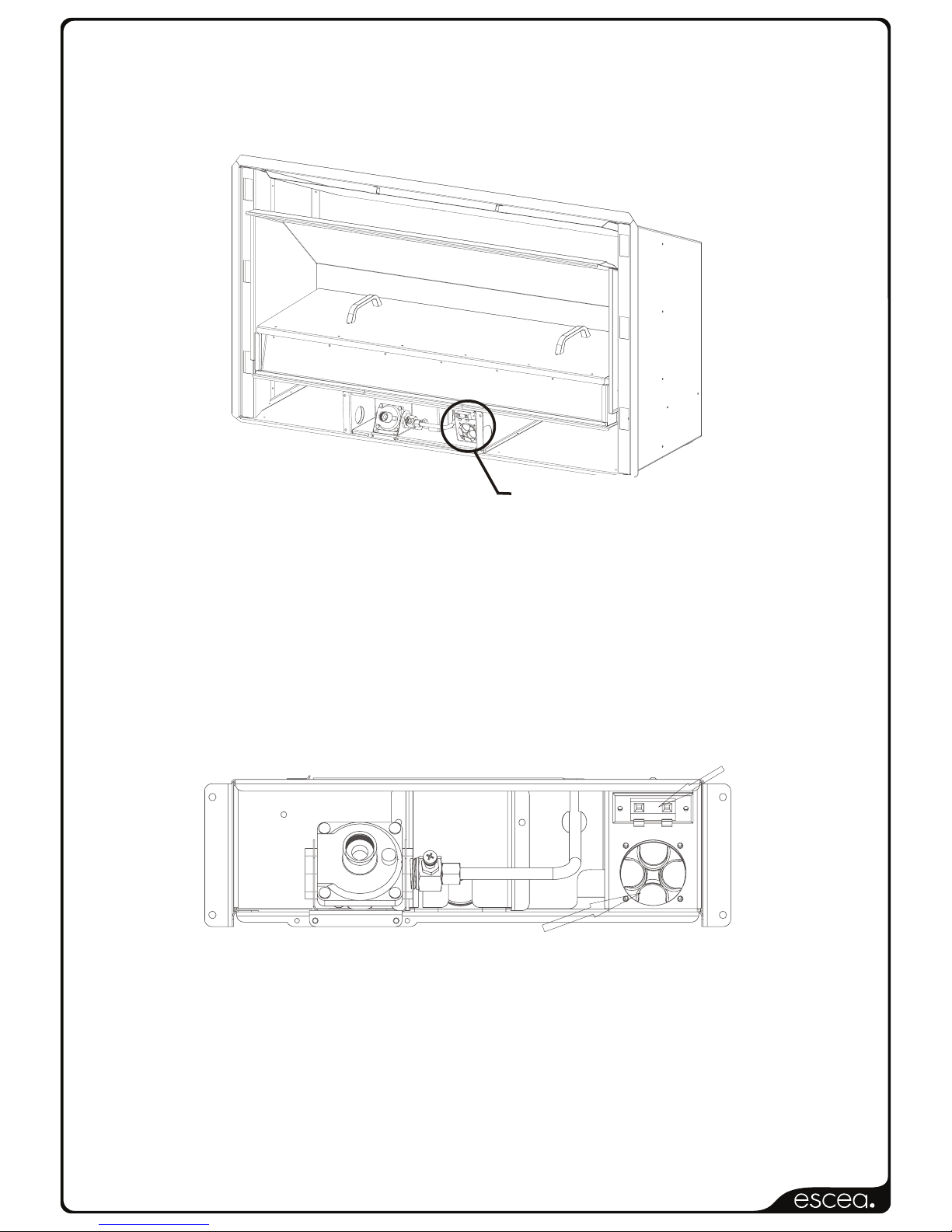
This appliance requires 3 ‘D’ sized cell batteries for operation, which are located in a battery
pack inside the control tray behind the fascia, at the base of the fire. Alternatively, you can
use the External Power Supply, described in section 2.2 of this manual.
2.1 Replacing Batteries:
To replace the batteries, remove the fascia to gain access to the battery pack pictured
above. To remove the cap of the battery pack turn it anti-clockwise until it stops, then pull.
The batteries inside should slide out. Ensure you replace the batteries in the correct way,
dimple facing out.
Once the new batteries have been placed inside, replace the cap and turn it clockwise until it
stops, to seal it.
2.2 Alternate Power Source: (Optional)
+VE -VE
Alternative Power source
Connection Terminal
Battery Pack
If you wish to connect your outdoor fire to mains electricity instead of using 3x D sized
batteries, you may do so using the Alternative Power Source Connection Terminal, located
on the control tray above the battery pack, as shown above.
You will need to purchase a transformer capable of 5v DC output, with a minimum of 1.3
Amp capacity. Connect the transformer to the fire by putting the Positive wire into the Red
terminal of the control tray, then connect the Negative wire to the Black terminal.
THIS MUST ONLY BE DONE BY AN AUTHOURIZED ELECTRICIAN
Battery Pack
Page 6
630162_2EF5000InstallationGuideR‐emotion‐US
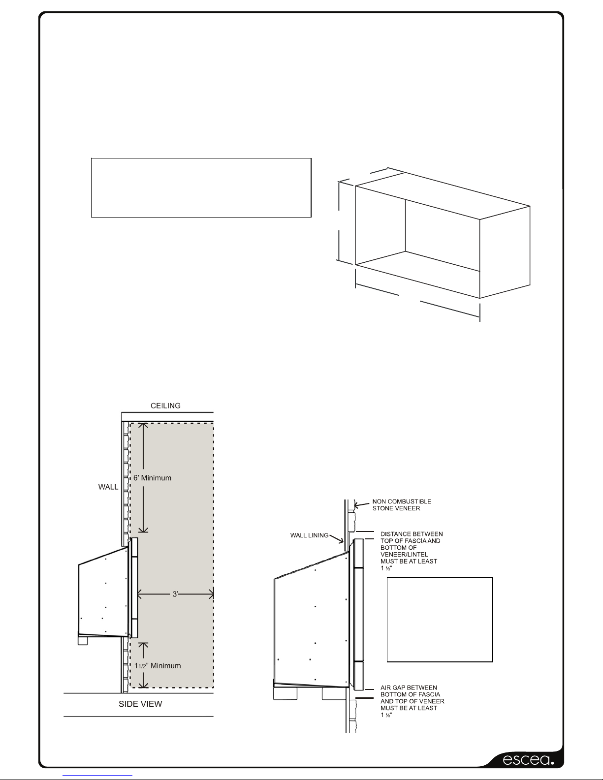
Ideal Cavity Dimensions
A B C
39 13/16“ 23”
13“
3.0 Creating the Cavity:
The dimensioned drawing below shows the size of opening that must be created to install
the unit.
4.0 Cavity Dimensions:
4.1 Where possible, it is recommended that the cavity is made slightly larger than the above
dimensions to give the installer the maximum amount of space to work in.
4.2 Clearances:
B
A
C
Minimum clearance distance between the ceiling and
fascia to be no less than 6’.
Warning: Under no circumstances should any object such
as people, pets, furniture, etc. be closer than 3 feet in
front of the escea EF5000.
Note: The 1 ½”
clearance is also
required on the
sides of the fascia
to allow access to
the control panel.
Page 7

630162_2EF5000InstallationGuideR‐emotion‐US
5.0 Wall cladding around fire:
5.1 The temperature of the wall directly above the heater will get hot and hence may discolour
paint finishes.
5.2 Some dark coloured exhaust stains may also become visible directly above the fire due to
exhaust. In most cases this can be cleaned off with water and a brush.
6.0 Minimum install height:
The fire has ventilation gaps behind the fascia at the top and bottom. These must not be
blocked, so ensure there is a gap of at least 1 1/2” between the bottom of the fascia and
anything below.
7.0 Types of Installation:
This appliance shall only be used in an open-air situation with natural ventilation, without
stagnant areas, where gas leakage and products of combustion are rapidly dispersed by
wind and natural convection.
Certain materials or items, when placed under or near the appliance, will be subjected to
radiant heat and could become damaged.
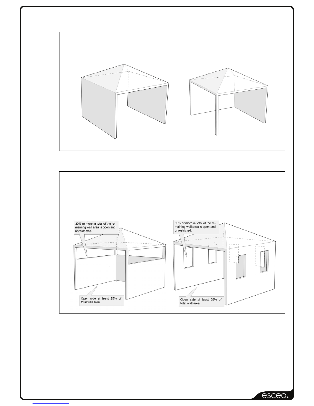
Typically an outdoor space is not enclosed but, any enclosure in which the appliance is used
shall comply with one of the following:
- An enclosure with walls on all sides, but at least one permanent opening at
ground level and no overhead cover.
Page 8
630162_2EF5000InstallationGuideR‐emotion‐US
- Within a partial enclosure that includes an overhead cover and no more than two
walls.
- Within a partial enclosure that includes an overhead cover and more than two
walls, the following shall apply:
At least 25% of the total wall area is completely open, and
At least 30% of the remaining wall area is open and unrestricted
Rectangular areas have been used in the above diagrams, the same principles apply to any
other shaped area.
In the case of balconies, at least 20% of the total wall area shall be and remain open and
unrestricted.
Page 9
630162_2EF5000InstallationGuideR‐emotion‐US
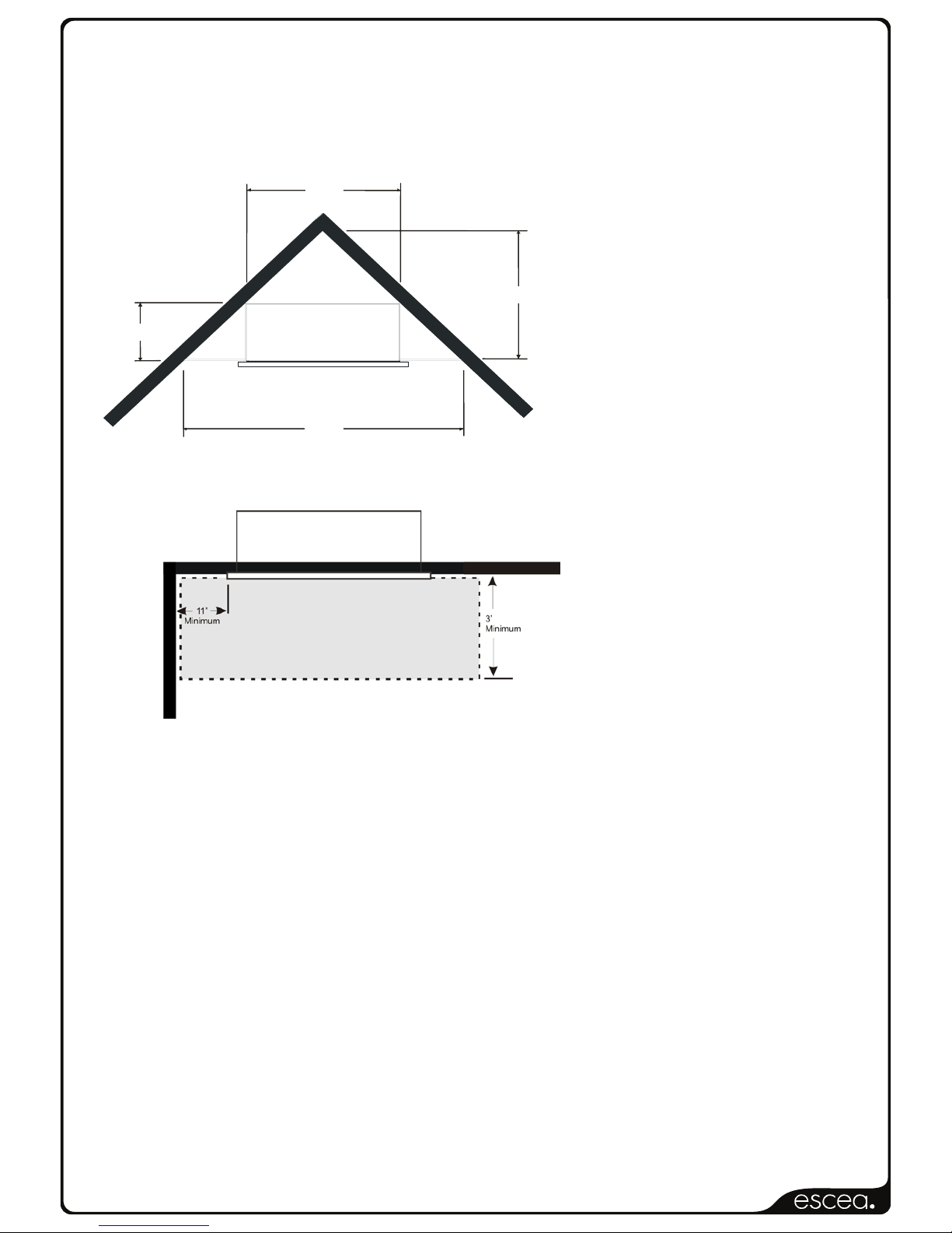
7.1 Corner Installations:
If a cavity is to be created in a corner, the following drawings give the minimum sized interior
wall dimensions possible.
Note:
Allowances need to be made for
the internal cladding of the cavity.
Dimensions of the cavity in this
diagram represent the internal
size only.
39 13/16”
32
7
/
8
”
13”
65 ¾”
Minimum clearance distance
between adjacent wall and fascia to
be no less than 11”.
Page 10
630162_2EF5000InstallationGuideR‐emotion‐US
8.0 Laying Gas Pipe:
Gas pipe should be sized as per the requirements of your local council. The pipe sizing must
be sufficient to deliver the following volume of gas to the heater with all other gas appliances
in the home running at the same time;
EF5000 = 60 Mj/hr - 56,000 Btu/hr
It is highly recommended to install an easily accessible isolating shut off valve (ball valve)
along the gas line to the EF5000 unit.
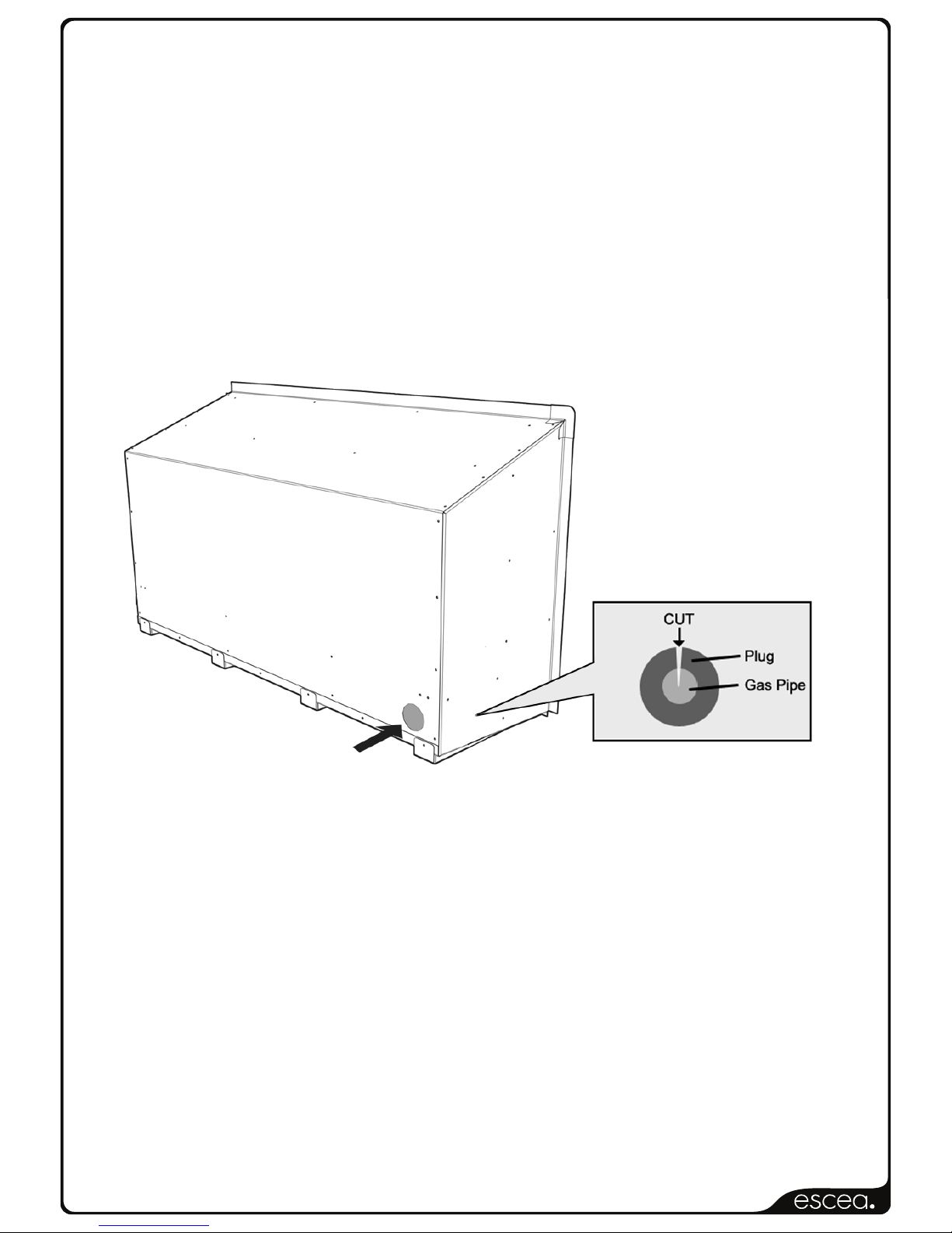
8.1 Solid pipe should be run to the inside lower left hand side of the fire. Insert the supplied
rubber plug and cut it as shown below to allow the gas pipe to pass through, keeping the
plug as air-tight as possible.
Gas Pipe Entry Point
8.2 It is required by law that an approved shut off valve (not supplied) be installed in the line
between the EF5000 Gas Fire and the gas supply.
8.3 All hoses and gas pipes must be located out of pathways where people may trip over it and
must not be in areas where the hose may be subject to accidental damage.
Page 11
630162_2EF5000InstallationGuideR‐emotion‐US
9.0 Fixing the fire into the cavity:
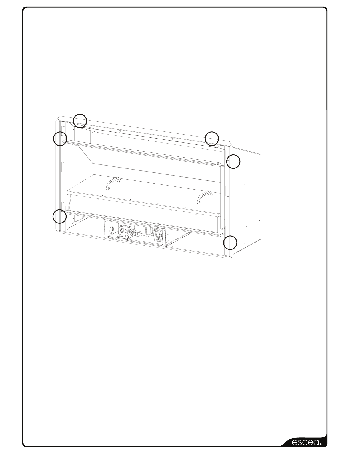
To fix the fire to the cavity, first drill 4 to 6 (3/16” diameter) holes in the outer flange (as
shaded grey in the picture below) in locations which will give you the most support from the
cavity framework behind, and evenly spaced around the flange. Using the supplied Stainless
Steel screws, fasten the fire to the cavity through these drilled holes.
Ensure that the fire is securely located and free from movement.
Suggested location of screws for mounting
10.0 Connecting the Gas Pipe:
When the fire unit has been pushed into position and secured the gas pipe can be
connected to the inlet side of the appliance regulator (BSP thread) at the front center of the
fire. The hose and pipe assembly should have been tested prior to this as per section 8.2
10.1 The regulator that is supplied in the fire MUST NOT BE REMOVED. Removal of the
regulator, or replacing it with one not intended for use with an Escea EF5000, will void the
limited appliance warranty.
10.2 The EF5000 must be isolated from the gas supply piping system during any pressure testing
of that system at test pressures in excess of ½ psi (14”WC).
The gas fireplace and its individual shutoff valve must be disconnected from the gas supply
piping during any pressure testing of that system at test pressures in excess of ½ psi (3.5
kPa – 14” w.c.).
Page 12
630162_2EF5000InstallationGuideR‐emotion‐US
11.0 Connecting the power supply and Touch panel:
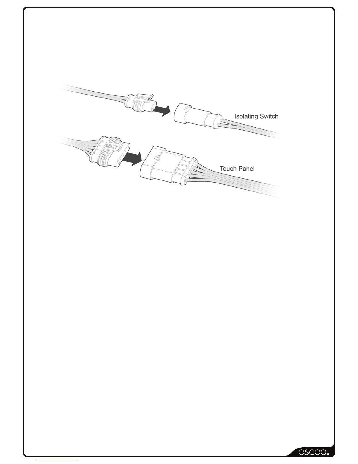
11.1 The Touch Panel and Power Isolating Switch are located in the RH side of the Fascia.
11.2 The Touch Panel socket and Isolating Switch socket plugs into the 5 pin plug lead situated
at the front RH side of the fire. Push them together until they ‘click’,
12.0 Testing of the Touch panel and spark ignition:
IMPORTANT: Before the operating pressure can be checked and the fascia fitted,
The touch panel and spark ignition must be tested.
12.1 This can be done with the gas supply either turned on or off.
With the power supply and touch panel connected, Lean the fascia Right end up beside the
fire and run through the steps for igniting the pilot (refer to section 17.0 for instructions).
Page 13
630162_2EF5000InstallationGuideR‐emotion‐US
13.0 Checking Operating Pressure:
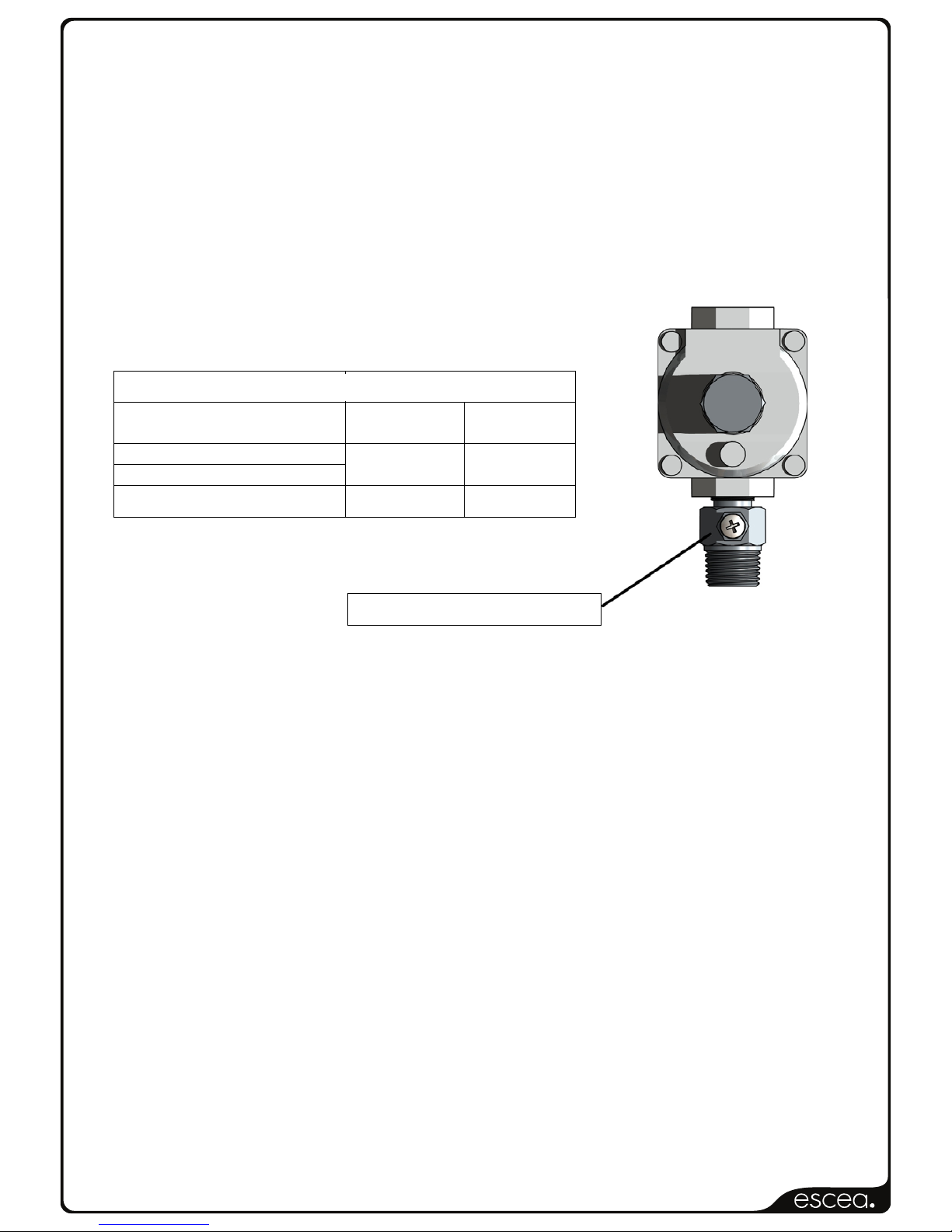
This is done at the regulator located at the lower front of the appliance.
13.1 This must be done before the fascia has been fitted.
13.2 The manifold pressure has been factory set. Please check that the manifold pressure is as
listed below by checking at the outlet test point.
13.3 Replace operating test point screw and leak test the test point.
EF5000 Pressure table
Propane Natural
Gas
Maximum Inlet pressure 20”wc 20”wc
Minimum inlet pressure 10”wc 5.5”wc
Manifold Pressure 10”wc 5”wc
EF5000 Pressure table
Propane
Operating pressure test point
Page 14
630162_2EF5000InstallationGuideR‐emotion‐US
14.0 Assembly of stone cartridge:
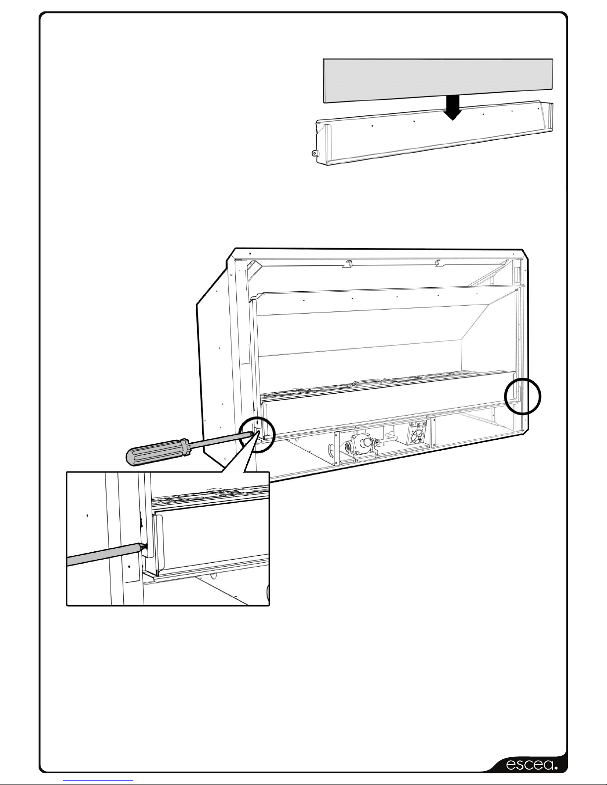
The glass which fits inside in the stone
Cartridge has been packaged to protect it
during transit, and can be found inside the
firebox. Insert the glass strip into the stone
cartridge as shown to the right, between
the two metal flanges and push it all the
way to the bottom. A bag of pebbles
(River Stones) are also supplied, use
these to fill the stone cartridge.
14.1 With the glass in position, fix the stone cartridge to the fire by using the two supplied screws
in the location shown below. Do this before the fascia is fitted.
Page 15
630162_2EF5000InstallationGuideR‐emotion‐US
15.0 Fitting the Fascia:
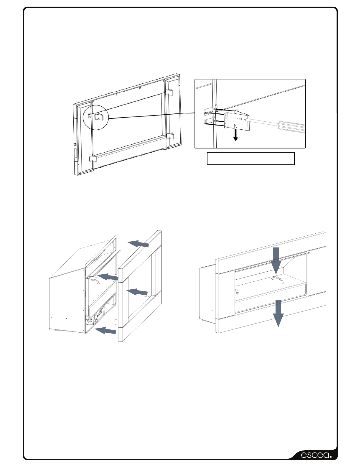
Before fitting the fascia, the hooks must be attached using the screws provided. Ensure the
two wires connecting the fascia to the fire are securely connected, as per section 11.0.
The EF5000 Stainless Steel fascia is attached to the combustion box by four ‘hooks’ on the
corners of the fascia.
Line up the hooks with the receptacles on the Outdoor Fire pictured below, and push the
fascia into position.
15.1 When you have pushed the fascia in as far as it will go, briefly push down on the fascia to
secure the fascia into position.
‘V’ in bracket to face down
Page 16
630162_2EF5000InstallationGuideR‐emotion‐US
16.0 Placement of ceramic stones:
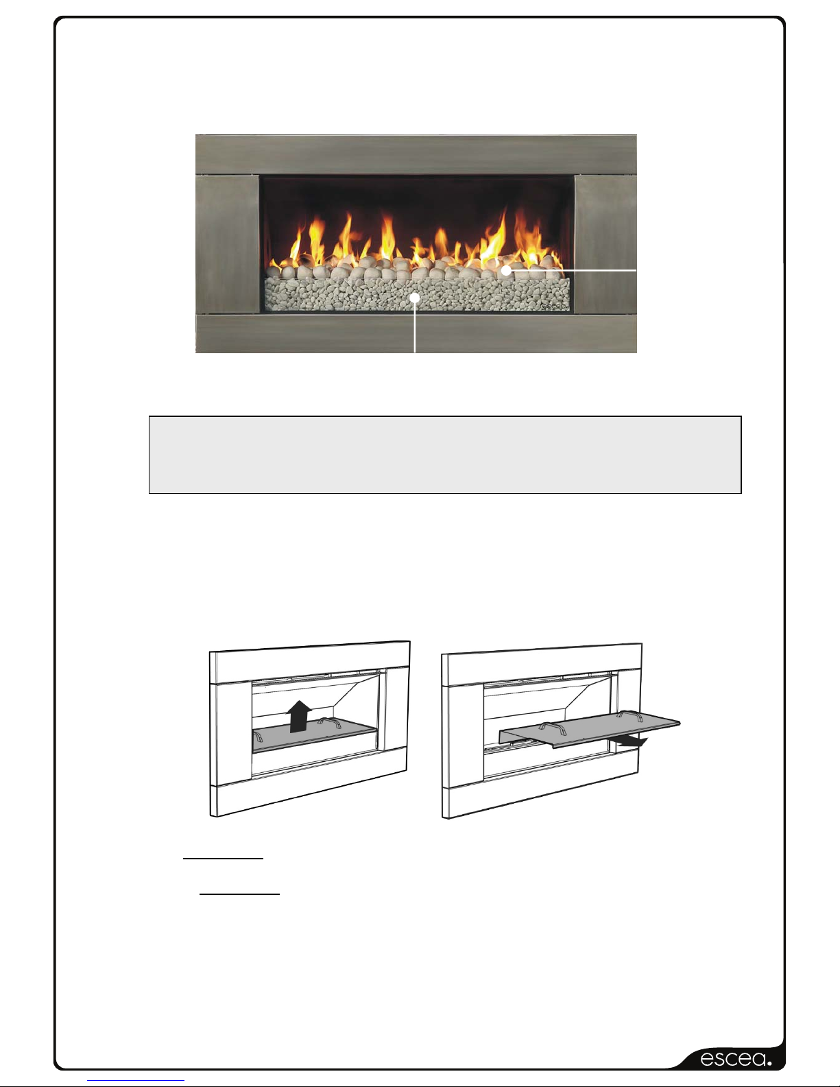
EF5000 fuel beds should be evenly spread out with a maximum one layer of media. Do not
heap or mound the fuel bed media, but attempt to get an even spread across the top of the
burners.
16.1 UNDER NO CIRCUMSTANCES SHOULD THE SUPPLIED
SMALL STONE PEBBLES (RIVER STONES) BE PLACED ON THE BURNERS.
THEY ARE FOR USE INSIDE THE STONE CARTRIDGE ONLY
16.2 The Weather Cover supplied protects the stones and burners. This must be replaced when
the fire is not in use.
16.3 To fit the weather cover ensure fire is off and cooled, and place the front edge on the glass
at the front of the fire, the rear flange of the Weather Cover will rest on the burner supports
behind the rear burner. To remove, lift the Weather Cover upwards and then towards
yourself.
16.4 The fire MUST NOT be operated while the cover is fitted.
16.5 The cover MUST NOT be fitted while the fire is hot. A cooling period of 30 minutes must be
observed before fitting.
16.6 Objects such as wood, coal, fire logs or any other solid fuels shall not be burned in the gas
fireplace.
Under no circumstances should any objects enter the gas fireplace during the start-up or
whilst the fire is running.
Ceramic
stones
River stones
Page 17
630162_2EF5000InstallationGuideR‐emotion‐US
17.0 Operating Instructions:
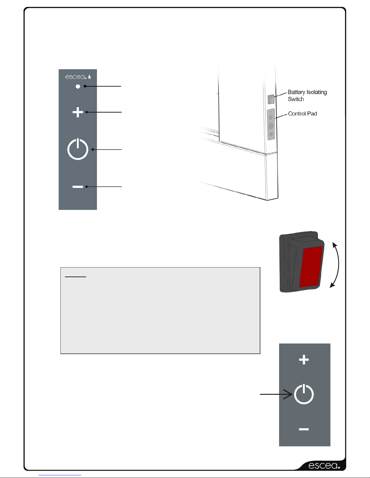
The EF5000 is operated by the touch control panel located on the Right hand side outer
edge of the fascia. The basic operations possible from the touch control are ON/OFF and
manual adjustment of the flame height.
17.1 Igniting the pilot flame:
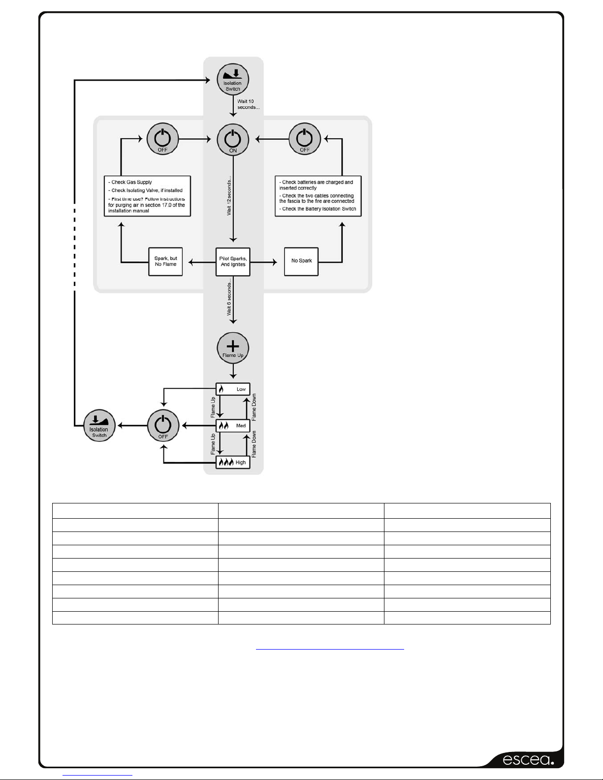
17.2 First turn on the battery isolating switch
To turn on the fire push the ON/OFF button (2) on the touch
control. The pilot will start sparking and gas will start flowing to the
pilot which should light and be visible in a few seconds.
17.3 The pilot ignition process takes a duration of 12 seconds. No
other button should be pressed during those 12 seconds.
In the event of the pilot not igniting after 12 seconds press the
ON/OFF button (2) this will turn the valve and gas off. Now repeat
the process from 17.2 until the pilot ignites.
1: FLAME UP
2: ON/OFF
3: FLAME DOWN
NOTE: The first time you attempt to ignite the EF5000 after
connecting it to a gas supply, will take between 1 and 4 lighting
attempts in order to let gas flow through the pipe system and
purge all air. To do this, push ‘power’ to switch the fire on and
wait for 12 seconds. If there is a spark but no flame, push
‘power’ again to switch off (you will hear a click) and then
repeat until you get a pilot flame.
Alternatively you can flick the battery isolating switch above the
control panel off and then on again. This will totally reset the
system.
GREEN DIAGNOSTIC LED
Page 18
630162_2EF5000InstallationGuideR‐emotion‐US
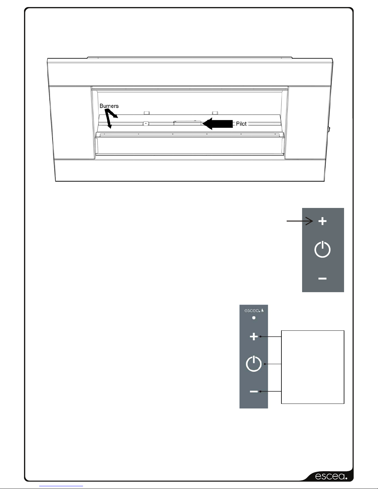
17.4 Pilot Flame and Burner Positioning
17.5 Turning on the main burners
Once the pilot flame has been running for at least 6 seconds press the
FLAME UP (1) button to start the gas to the two main burners
17.6 The EF5000 has 4 flame positions: PILOT flame only, LOW burner
flame, MEDIUM burner flame and HIGH burner flame.
17.7 Adjusting the flame height
While the fire is on, push the FLAME UP button (1) or the
FLAME DOWN button (3) to increase or decrease the
flame height.
17.8 If the FLAME UP button (1) is pushed while the fire is in
HIGH burner flame position, nothing will happen.
Similarly if the FLAME DOWN button (3) is pushed while
fire is in the PILOT flame position, nothing will happen.
17.9 Turning off the fire
To turn the fire off, you must push the ON/OFF button (2) this will shut down the gas flow to
the pilot flame and both burners. Then turn off the isolating switch.
1. FLAME UP
2. ON/OFF
3. FLAME DOWN
Page 19
630162_2EF5000InstallationGuideR‐emotion‐US
18.0 Maintenance and Cleaning
The unit must be cold before starting any form of maintenance or cleaning. To remove the
glass and stones in the front stone tray simply reverse the steps in section 15.0. The glass
can be cleaned using standard window cleaner and the quartz stones can be washed using
soapy water
18.1 For cleaning the stainless steel fascia the following products are recommended; 3M
Stainless steel cleaner, methylated spirits with a clean cloth
For cleaning the powder coated Fascia/ weather cover use soapy water and a sponge or a
clean cloth.
Cleaning of the burners and ceramic stones can be carried out using a brush and a dry cloth
and should be done at least annually. This will remove carbon or soot build-up.
Periodically the pilot and burners should be checked visually for carbon and soot build-up,
consistent flame and clean burning.
18.2 Periodical visual checks of the pilot and burner flames should be carried out to ensure
consistent flame and clean burning, then turn off the battery isolating switch.
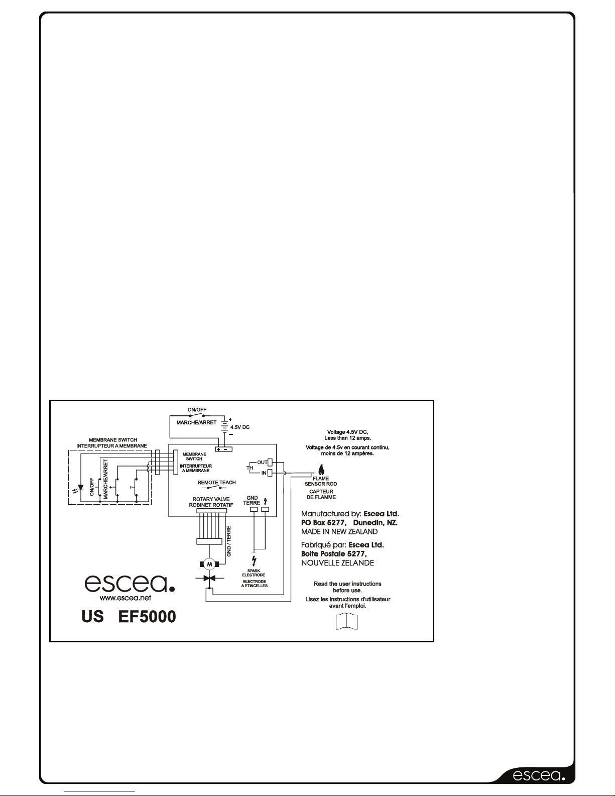
19.0 Electrical Schematic
Part No. 620261_1
i
Page 20
630162_2EF5000InstallationGuideR‐emotion‐US
E
F50
00Repla
ce
mentP
a
rts
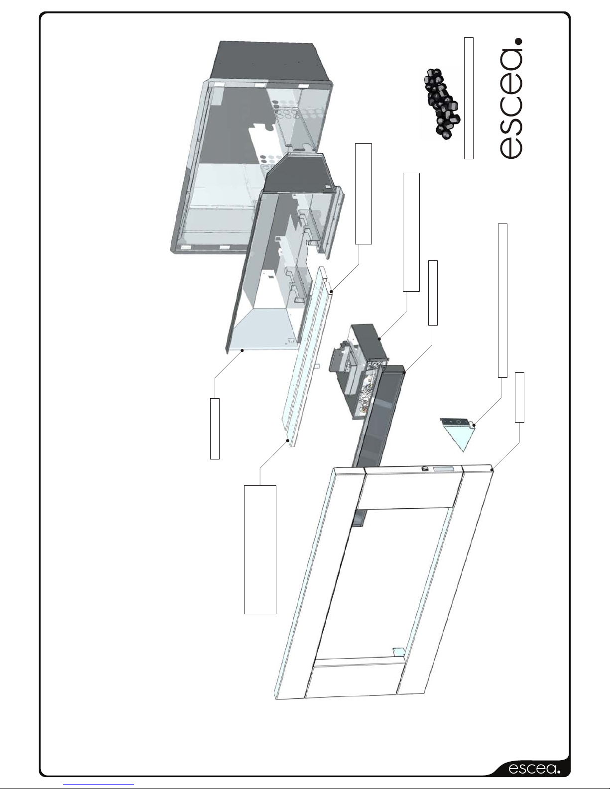
820100 Large White Ceramic Stones
820132 Membrane Switch and Control Bracket
820101 StoneTray
Ignition Tray
Ignition Tray
NATURALGAS
LPG
820020 Burner
820021 Burner
LPG ( 1)
NaturalGas (1)
820220 Conversion Kit
820221 Conversion Kit
FROM LPG TO NATURALGAS
FROM NATURALGAS TO LPG
820001 Firebox
820150 Fascia
Please use part numbers listed if ordering replacement parts.
820128
820129
Page 21
630162_2EF5000InstallationGuideR‐emotion‐US
19.1 Operation Chart
LPG Natural Gas
Min. Inlet Pressure 10”wc 5.5”wc
Max Inlet Pressure 20”wc 20”wc
Manifold Pressure 10”wc 5.0”wc
Front Burner Jet Size 0.063” 0.125”
Rear Burner Jet size 0.063” 0.125”
Front Burner Aeration Hole 0.433” 0.236”
Rear Burner Aeration Hole 0.433” 0.236”
BTU 56000 54000
For certification inquires, please contact [email protected] or contact our Client
Services Centre at 1.866.797.4272 or (416) 747-2661
CSA.
Cleveland, Ohio
8501 East Pleasant Valley Road
Cleveland, Ohio, USA, 44131-5575
Page 22

630162_2EF5000InstallationGuideR‐emotion‐US
LIMITED WARRANTY:
Provided that the Product is installed as per ESCEA's Installation Manual and the step by step warranty procedure has been
followed as per instructions issued by ESCEA, (documented in the Dealer Manual), and the prod uct is operated and maintained in
accordance with ESCEA operating and maintenance instructions, then for the first period of twelve (12) months from the date of
purchase ESCEA will pay to the dealer who sold the appl iance, a pre-determined sum to repair or replace any part of the Product
that is deemed by ESCEA to be faulty.
For the second period of twelve (12) months from the date of purchase ESCEA will supply repl acement parts only, without charge.
Parts and Labor for the first twelve (12) months:
a) ESCEA, at its sole discretion and through its dealer, may modify, adjust, repair, or replace the faulty products. The warranty
period on parts and labor shall be for twelve (12) months from the date of purchase.
b) Pre-determined labor costs will only be reim bursed when ESCEA specifie d procedure has been foll owed, and ESCEA has
authorized service work before it was carried out.
Parts Only for the second twelve (12) months:
a) ESCEA, at its sole discretion, will provide replacement parts to its dealer for the ben efit of an end user. Faulty parts MUST
be returned to ESCEA. The parts only warranty period shall be for t welve (12) months and will commence twelve (12)
months after the acceptance date of the Products by the ESCEA retailer.
General Terms and Exclusions:
1. All repairs made within the Limited Warranty period shall b e covered by this Limited Warranty for a period of three (3)
months from the date of completion of the repair, or for the remainder of the overall Limited Warrant y period, whichever is
the longer.
2. If the buyer or any other party modifies an y part of the product within the Limited Warranty period without the prior written
consent of ESCEA then the Limited Warranty shall be void.
ESCEA may, at its sole discretion, decide that the Limited Warranty is void in relati on to any part of the prod uct, which has
been modified.
3. ESCEA must be notified of all claims under this Limited Warranty as soon as possible, but in any ev ent not later than two
(2) weeks of the claimant becoming aware of the circumstance giving rise to the claims.
4. No ESCEA Distributor, retailer, employee or other third party is authorized to make any modific ation, extension, or addition
to this Limited Warranty, whether verbal or written.
5. ESCEA reserves the right to discontinue products or make substitutions, in suc h event, the buyer may receive a substitute
product or a cash refund at ESCEA'S sole discretion, if a replacement for the product covered by this Limited Warranty is
no longer available.
6. ESCEA is not responsible for damage arising from failure to follow instructions for the product's installation, mai ntenance
and permitted and proper use. The Limited Warranty does not cover damage caus ed by use with non-ESCEA pro ducts or
damage caused by accident, abuse, misuse, weather, fire, flood, earthquake or other external causes. Products where an
ESCEA serial number has been removed or defaced or damage caused by incorrect fuel type or flueing are also not
covered. Cosmetic damage, including but not limited to paint blemishes, scratches, non structural surface rust, water
damage and normal fair wear and tear are not covered as well. Gas Fir ep laces requ ire annu al serv ice, problems ca us ed by
not having this service done such as (but not limited to) dust and debris build up, flat b atteries, insects present in burners,
incorrect gas pressure and worn thermocouples are also not covered under this warrantee.
LIMITATION OF REMEDIES:
TO THE EXTENT PERMITTED BY LAW:
This limited warranty, and the remedies set forth above, are excl usive and in lieu of all other warranties, remedies and con ditions,
whether verbal or written, statutory, express or implied.
Escea specifically disclaims any and all statutory or implied warranties and conditions, including, without limit ation, warranties of
merchantability, fitness for a particular purpose and warranties against latent defects.
Except as provided herein, Escea is not responsible for direct, special, incidental or cons equential loss or damages resulting from
any breach of warranty or condition, or und er any other legal theor y, including but not limited to the l oss of any of th e follo wing: use;
revenue; actual or anticipated profits (including loss of profits on contracts); use of money; anticipated savings; business;
opportunity; goodwill; reputation; any or indirect or consequential loss or damage ho wsoever caused including the replacement or
equipment and property.
Some states in Canada and in some States in the United States do not allow the exclusion of inc idental or consequential d amages,
so the above limitation may not apply to buyer.
 Loading...